


Horio
-
Posts
175 -
Joined
-
Last visited
Content Type
Profiles
Forums
Events
Posts posted by Horio
-
-
I mounted the transistors to the Hifi2000 heatsinks yesterday, and I thought I'd post a couple pictures. I had Front Panel Express do the drilling/tapping of the holes. They aren't the cheapest, but did a great job and everything lines up perfectly.
If you are interested, I'd be happy to send you the FPE files (just shoot me a PM).
-
I like it spritzer. I think I'll do something similar, as rear mounted power switches are a pain to access in my rack.
-
Would one of you guru's mind posting some basic instructions for bringing up the KGSSHV Amp boards?
I have a healthy PS ready to go, and I'm going to be ready to test my amp boards (off board sinks) this weekend. Just wondering what basic voltages I can check to make sure the amp is working correctly, and if there is a suggested order/method for adjusting the trim pots.
Thanks!
-
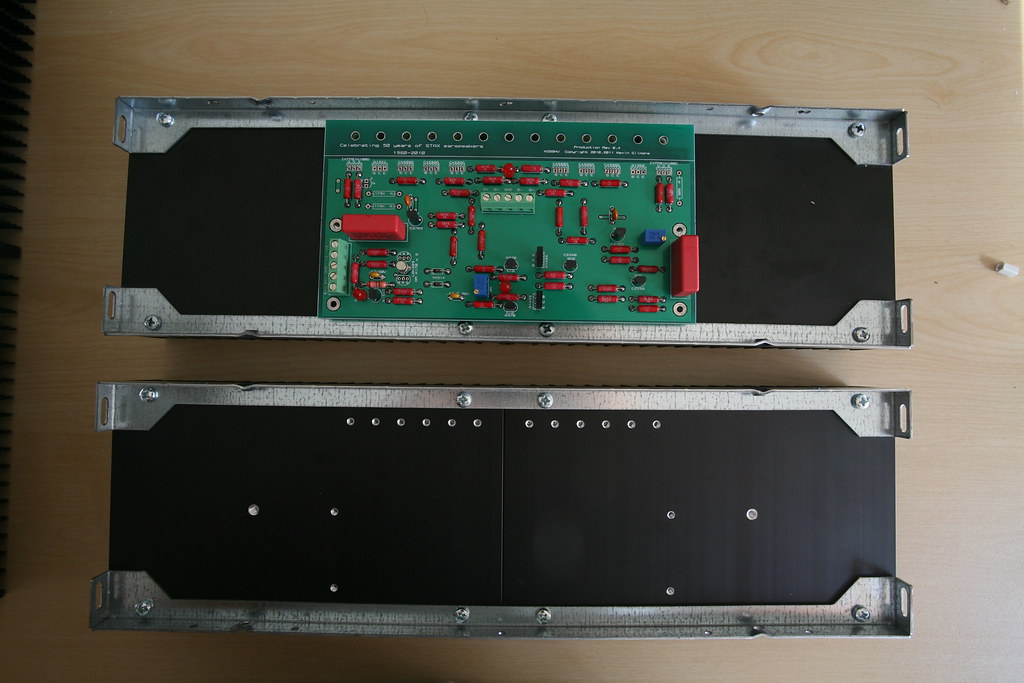
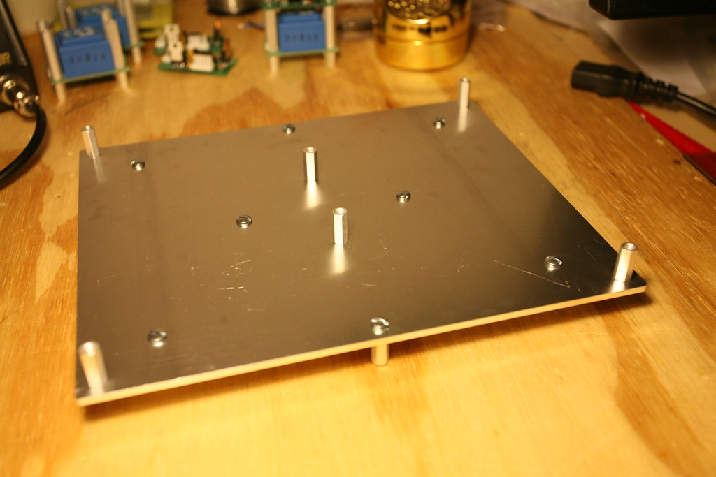
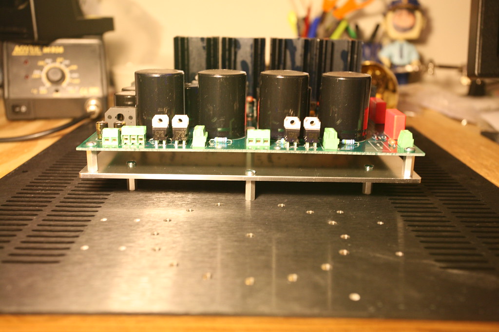
Here are a few more photos of my chassis work.
Unfortunately the Hifi2000 Dissipante cases have two rows of vent slots right where the power supply mounts want to be located. To get around this I created a mounting plate. The power supply mounts to the plate, and then the plate mounts to the bottom chassis panel. A little bit of a strange solution, but its quite sturdy and seems to have worked well.
-
Oooo, nice! You mind telling us what part you are thinking of using, or is that a secret?

-
I was thinking about the washer and nut on the heatsink side. Screw , washer, transistor, thermalloy, heatsink, washer, spring washer, nut.
Those were my plans exactly.
-
PEEK screws are a pain to get here in the antipodes.
$57+ for 100 m3 x 12mm screws and almost $90 for shipping........... Nuts & washers, ditto..
I'm feeling more like Birgir every day......
I bought the M3 PEEK screws, but I am planning to use a metal "heavy hex" nut and nylon washer from McMaster-Carr. The heavy hex nut has more depth than the PEEK nut, so you should be engaging even more threads on the screw. In theory, this should actually make it more difficult to strip. Nylon washers are dirt cheap too, and I don't really see the need to spend $50 on PEEK washers. You should already have plenty of isolation from the PEEK screw alone.
-
I'll look through the thread for the 450v specs.
I believe the only difference for the standard build (450V output), is the two HV secondary windings want to be 420Vdc@150mA.
-
You definitely need the thicker Aluminum Oxide Pads that Wink posted. Though they aren't very cheap, the PEEK screws are really what you want for mounting the semi's to the sinks as well. No sense "skimping" on a build of this nature and cost.
-
The epsilon 24's are going to run the anti-vandal momentary power switch and power relay.
-
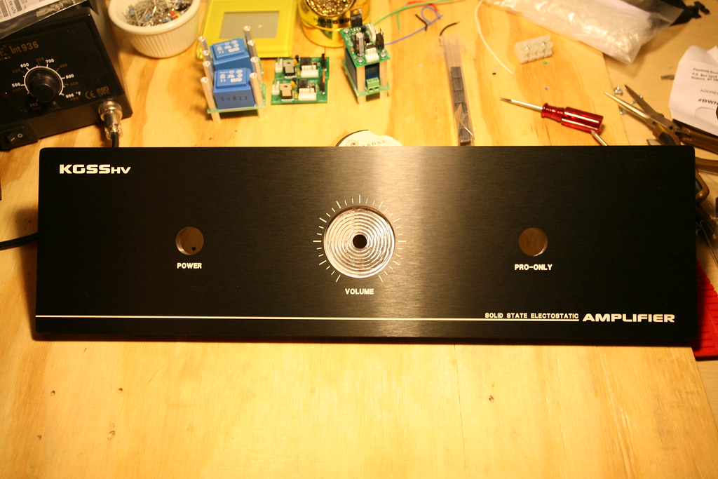
Theres a typo I just noticed..."Electostatic"...missing 'r'.
 Looks nice though!
Oh snap! Not sure how I missed that one... I must have been to worried about the cavities and all the holes lining up correctly. Oh well.

The stack jack fits great on the rear side of the panel. The blind tapped holes all lined up perfectly.
-
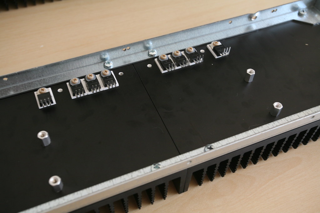
Got my panels back from Front Panel Express, and they look great. I had them do the drilling/tapping for the heatsink mounted semi's. I'll try and post some pictures of that setup this weekend, when I start assembling the amp. Here's the front panel (thanks to ujamerstand for the layout).
-
Just realized there isn't a 490K for the Xicon. You can use the 487K or you can leave the 442K and switch the 20K to an 18K. Either will get you close to 500V.
I swapped out R6 and R16 with 18K resistors (left R5, R15, R29, R30 at 442K), and I'm now getting +/-504V. The bias is also nice and stable at 580V without the voltage multiplier. Seems like my 500V power supplies are working well.
-
I have a bunch of matched 2SK170 pairs (Idss matched at room temp) I am thinking of using on the amp boards. From your experience, how important is thermally coupling the JFET pairs? The other option would be to buy some LSK389's.
-
Not yet. I ordered them last week. I had batchpcb to send them to Horio, who might need them earlier than I do. Maybe he could take some pictures when they arrive? my plan is buy some long M3 screws and some 6~7mm nylon standoffs to mount the pcb on the jack; then hook up the wires to the phoenix connectors on the bottom.
I'll take some photos as soon as they arrive, and post them here.
-
Thanks Kerry.
I had a feeling there were a few resistors I needed to change the value of. I'll get those parts ordered this week, and let you know how it works.
-
540V on the positive rail, 550V on the negative rail. Are there some resistor values that needed to change as well? The power supply sure thinks its a 450V setup.
-
So I powered up the Power supply, and I'm getting +/-450VDC. That would be great if I wasn't trying to go for +/-500VDC. I'm getting about 570V if I measure the Bias (before the 5M resistor) to the ground.
I've got a 550V string of zeners (200V + 200V + 150V) at D3, D4 and D5. Under no load, my SumR transformer secondaries are measuring about 520Vac. I have not populated the voltage multiplier parts, and I have soldered a wire at the bypass.
Any ideas of what I forgot to do?
-
Quick question before I power up the power supply for the first time. Is it safe to power up the PS without a load?
-
I'll take a few. You should set up a sign-up sheet. I have a feeling there is going to be interest...
-
So i finally had a few minutes to test the prp resistors last night and
while you can put 350 volts across them, and they are stable, If you
put them very close to the ground plane, they leak current thru
the covering on the film. So the prp's probably work if you lift them
off the board say .125 inch. But really there is nothing wrong with
the xicon's.
So is there a possibility of the same noise issues on the KGSSHV if I used PRP resistors mounted flush against the amp boards?
-
No thermal interface material either?
Just some thermal paste.
-
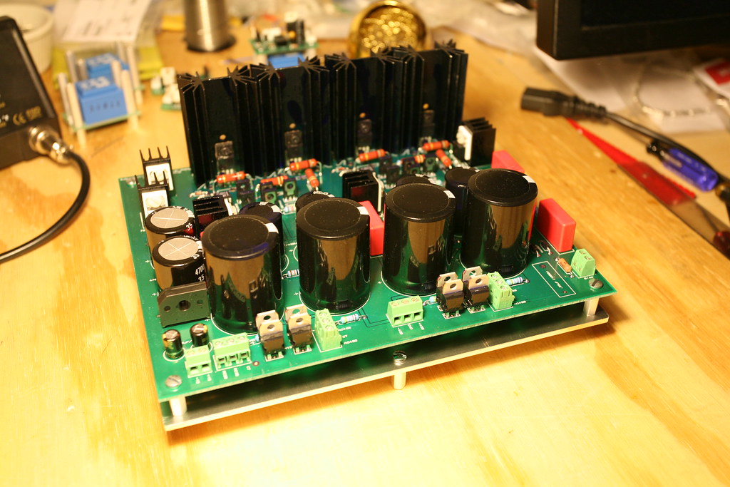
Nice work on the PS's Horio!
I llike to duck under the table with a voltage meter tied to the outputs when I first turn a new build on
EDIT: Just looking at the photos again, I can't tell if you have insulators mounted behind the output fets.
That doesn't sound like a half bad idea.
Regarding the output fets, I have the isolated version of the part (version FQPF8N80C). They are attached to the sinks without an isolation pad, as my understanding was they are already isolated. It would be good to know my assumption is way off here, before I plug it in. I am more of a builder than an electronics wiz.
-
Yes. High voltage can be lethal.
But you already know that. Right?
Please be careful.
That's what people keep telling me...
I will definitely be taking the appropriate precautions.Edit: NVM, why do have three PSs, are you building for other people?
Yea, I'm building three amps.

i'm on a roll... the kgsshv
in Do It Yourself
Posted
Yea, I knew the 2SC4686's are already isolated, but I decided to put the ceramic pads under all of the parts. They lined up, height wise, better this way with the boards. You need about a 3/8" tall standoff for the way I have it mounted (1/2" is just a bit too tall).
The two outer holes are for holding a cable management clip.
The screws are PEEK's, 10mm to be exact. With the depth of the holes (6.5mm), the 10mm PEEK screws are a perfect fit with the ceramic isolator pads. I know its a bit overkill, but I wanted to avoid any shorting issues on the IXYS parts. You have to buy 100 of them at a time, so I threw them on the other parts as well.