


congo5
-
Posts
167 -
Joined
-
Last visited
Content Type
Profiles
Forums
Events
Posts posted by congo5
-
-
so 4.5ma?
I did not change it cause did not feel I needed to
would think 9ma is enough
not telling people what to do
just what the stock values were from Kevin
-
1 hour ago, jose said:
the values that Congo5 selected.
my board is a direct copy of Dr Gilmore's layout and values.
so all credit goes to him.
I saw no need to make resistor value changes.
Some things can be adjusted as Michael did but with enough heat sink it works just fine as is.
A stable temp is good if you want stable current through the output stage
think mine were about 18ma warmed up on 400v rails
I have two working amps and no plans to mess with them.
Thanks
-
 2
2
-
-
Yea, good enough for me
on USA ~122vac with an Antek AS=1T300
and my "as built" BH supply
pick a transformer, measure its output.
build your power supply and test what it needs to regulate
then adjust accordingly, might not have exact output you want, doesn't matter if within 10% or so
if I send my transformer and PS to Jose it might not work good enough on his line voltage
you have to test and set it up or run a bit more regulation and heat to have some headroom
-
On 8/18/2018 at 4:24 PM, Laowei said:
the values shown
Yes, have made boards from those gerber's and they work just fine.
51 minutes ago, Laowei said:KSA2752 are still BO until November.
when I last ordered some (19-Oct-2017) it said Jan 2018
-
for the CCS power should go through the LED to the base and also to 10k string to other side
not emitter to resistor string
cut trace at E and connect to base
IF same as your board
make like schematic.......?
-
at one point there was an error on that board, Kevin fixed it
problems were, both outputs stuck on -3V, adjusts only .1v, OP07 servos do nothing, lower LED not lit,
I abandoned it and moved on to a newer version after finding this:

-
On 7/10/2018 at 10:45 PM, mwl168 said:
This is a great sounding amp. For the parts cost (when you can get them), this ES CFA probably takes the crown of the ROI of all the ES amps I have built.
So Glad you like it. never sure what someone else will think / hear
its a good thing I did not build this first
might have found an even more expensive hobby
-
Yea OK thanks, enough amps to kill the cheep bridges I was trying to use
I forget things that don't come up,
but hey I'm OLD -
I don't know about the 25A draw
not sure / don't remember
inrush was above that judging by damage at times
should have measured it but didn't
the average magnetic 15A circuit breaker might take 80A to trip instantly
I sometimes see startup amps on a 3ton A/C go over 110A on 25A fuses and 30A breakers
was using 4 boards
it was two years ago
think 5A running on 120v circuit or about 600W at idle from the wall
and that's with a low bias of 1A per board 1/4A per pair, 150mv each 0.47R emitter resistor
Yes that 90% efficienct 800W P/S looks right to me for two boards.
It depends on your speakers, 8ohms? 4ohoms?
how much power they and you require.
How much Bias / class A power you plan on
if balanced each board only sees half the load so an 8R becomes 4R when calculating Class A or power supply needs
-
There are resistors that fit better but I saved a lot of money by getting 100 Xicon's
Yes its a very tight fit
That SMPS looks interesting to me and its current limited to 1050W, would add the fan for sure.
I would like to try it, with two 50v feeding the unreg and with the GRLV set to 40v or slightly lower if using balanced as I don't really need 640 Watts RMS class AB
been wanting to take mine apart and make it into mono blocks that could be used as stereo or balanced and so it wouldn't weigh 80LBS
also need to double the size of heatsinks or add water cooling
And Yes I had trouble on startup with 1000va of transformer feeding close to 200,000uf of caps
the current inrush blew 12 35A diode bridges and the resulting short to ground blew up many of my soft start components
-
1 hour ago, kevin gilmore said:
Original downloads work for me?
yes but you =SuperStar
first links no=go
second work, Thanks
-
The amp camp was meant to be an easy to build and safe introduction into the hobby.
I have six Amp Camp stereo amps so as an intro it worked quite well
All are used for phones, they will drive Fostex T50's loud enough to quickly damage your hearing.
None of my off the shelf 89db/W speakers work well with this amount of power.
not that it sounds bad just not enough drive to wake them up.
the F5 does do the job.
you might like them, you might listen differently
think small room, efficient speakers, modest volume
DiyAudio sells quality kits and have excellent documentation
+1 what Craig & JimL said
-
1
-
 1
1
-
-
The problem with mounting the 10m90s for CCS 580v bias is that there is a lot of voltage on that metal tab
I have not measured it but it has to be well over 600v
the heatsink is 6/32 mount hole
most times the transistor hole is too small for any PPS washer I have to fit
they will crack if you force it
and the PPS washers require a M3 or 4/40, so no 6/32 screw
good news is there is not a lot of heat here as its putting out ~1.5ma
so I have used a nylon 6/32 with 2mm oxide pad and thermal grease
Peek would be better
have also reamed out transistor hole before mounting to fit washers
and 4/40 SS screw with nut through heat sink hole
this is all covered in one of the older threads but they are large
600v when let loose is exciting and yes I have had flaming boards
this is what I get away with YMMV
-
1
-
-
In the Blueman2 picture above it looks to me like a metal screw in the 10m90 for the headphone bias CCS
And if so, do they make PPS washers that are white?
It looks good but for that one concern
thanks
-
1
-
-
what zeners? no see um
-
4 hours ago, jose said:
Those who have tried this, what do you prefer?
The THAT340 is a sub for jfets, because they are hard to find and costly
I changed mine because offset would move 100mv over the range of pot.in hindsight might be just wiring, or solvable with a couple resistors to ground.
that pot /bjt input interaction could also cause noise
sounds very good both ways
-
What bias are you running?
I turned mine down by stacking another resistor IIRC
and have sinks glued to the top of transistors
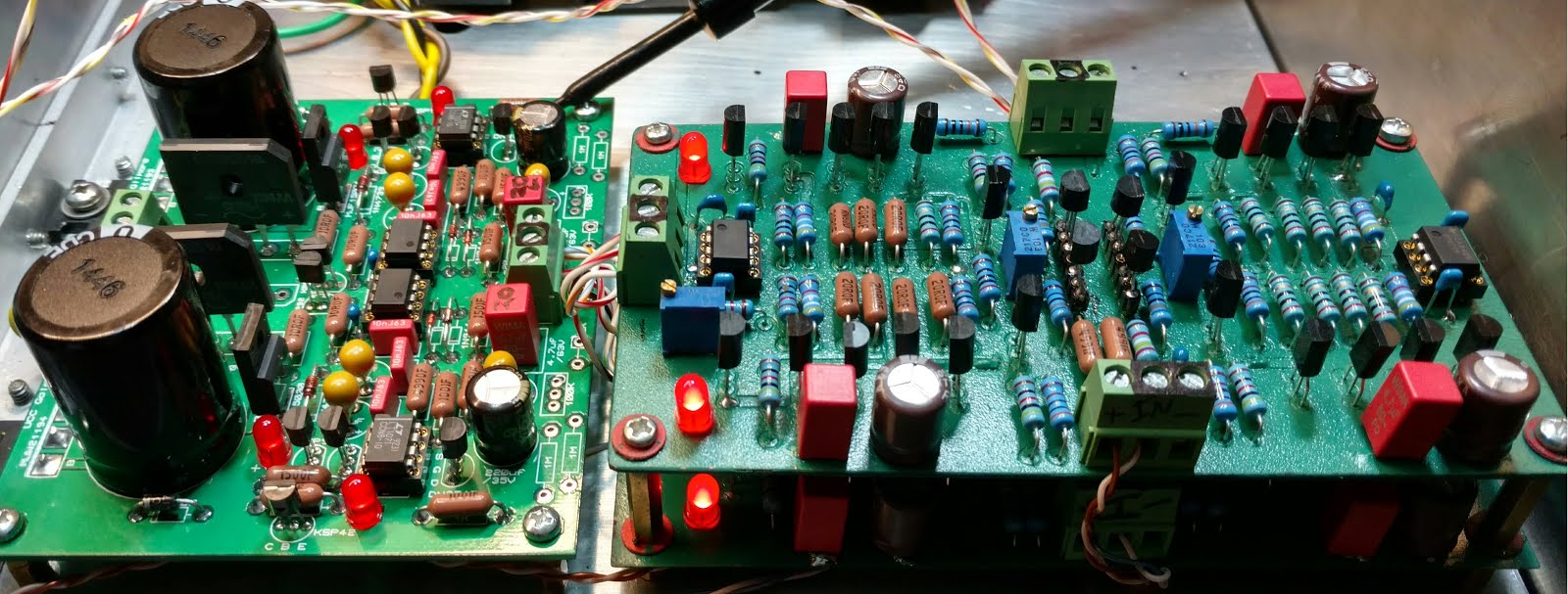
There is lots of copper on Kerry's board but a limited amount of surface area to dissipate heat.
mine runs cooler in the case if I turn it on its side so air can rise vertically along the board surface.
But yes ..............in a tiny case it runs hot.
(from notes on ssdynalo mini)
255R bias +1.8k =223Ravg .280mv/20R=14ma .28W -
well then my Jfets are exactly backwards for K170 J74
but those are K246 J103 so OK (if it matters)
they did work fine here but not so in Dynahi, used K170 J74
the silk is marked so
Emitter – (E) >> Source – (S) Base – (B) >> Gate – (G) Collector – (C) >> Drain – (D) -
1
-
-
I saved that pic but can't find it
here is my SSDynalo with jfets
N channel on top
P channel on bottom
-
2
-
-
Looks to me like these could sub for input transistors.
And PBHV3160ZX
data sheet is very much same except for lower collector and emitter capacitance
Yes/No?
-
no its complete, SE in or BAL
-
at bottom center of each side are two holes for a solder loop or I plan to use spade connectors
that is where Kevin put them and I copied his work
Another benefit for the different caps are that they are shorter.
So the board assembly is smaller
-
1
-
-
Yes I consider artistic ground planes "Fancy"
This amp seems to have very good noise rejection as I can't hear anything.
but why not have a ground plane......
This is what I will make next, when the parts come in
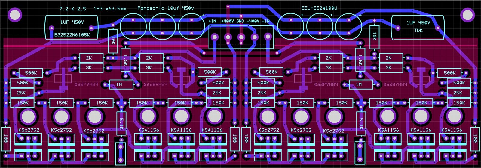
Think this is better then my last, with ground plane, lower ESR and a bit smaller.
-
2
-
-
39 minutes ago, Pars said:
single-ended CFA2 (or is that CFP2)?
File names are CFP2 which stands for Current Feedback Amp so sometimes referred to as CFA
CFP2 is SE CFP3 is balanced and Large
I have built dmt ver1.05, emt ver1.06, and had boards made and built fmt ver 1.07 which are 3.7" x 4"
they all work
gmt Ver1.09 is the newest
from memory there were small changes only between them
what part of schematic does not match?
its been a while but will try to help
current feedback electrostatic amp
in Do It Yourself
Posted
looks like I'm the one that caused trouble, not you....
those sinks above are much bigger than mine.
you should be fine but do watch temps and measure across the 100r if you want to know what its running at ...