


jamesmking
-
Posts
382 -
Joined
-
Last visited
-
Days Won
1
Content Type
Profiles
Forums
Events
Posts posted by jamesmking
-
-
3 hours ago, jokerman777 said:
Wanted to buy some FQPF8N80C seems uk rs-online only let me enter UK address, is there a way to get them ship worldwide?
-
On 6/19/2023 at 11:42 PM, audiostar said:
Mouser has a couple of MJW21193G, grab them while they last.
they are gone already.
radio spares has some
-
57 minutes ago, sorenb said:
@jokerman777
The thermal compound looks kind of grey'ish ... do you use some exotic compound?
The screw needs to be able to slide into the 7721 without any force, otherwise it is too big.Maybe you found the cause of the HV transformer buzzing with "no load" ...
personally I use Arctic Silver Ceramique 2 it is non conductive is not metal based and I have had no issues with it so far.
-
8 minutes ago, sorenb said:
STTH512FP is ready available and fully insulated.
If you look through the KGSShv thread, some had troubles with un-insulated rectifier tabs shorting.
yep, there is a lot of voltage differential across those tabs. I only use STTH512FP so far zero failures zero issues with them.
-
1 hour ago, jokerman777 said:
Things I know so far:
-Chassis/earth ground is now shorted to on board signal ground, either through the case of 7812 or I might have a short somewhere else.
-The anodes of the 10m90s at the +500V/Bias supply side are shorted to gnd, so either one or more of these might have the case shorted to the bracket or I have dead diodes causing it.
-On the other side where the sparkle happens the cases of all the transistors are not shorted to the bracket.
-Disconnecting the HV trafos power on again +-12V supply still works
I know this is way too little information to find out what went wrong other than I have one or more things shorted, I will take it apart further inspect this wknd
When testing without load is it ok to run the PSU without heatsinks installed? As that will save quite some effort since I likely need to do multiple iterations of trouble shooting.
if the +-12V rails work (with no load some voltage regulators will not regulate properly and most have current and thermal limiters built in) then its highly unlikely the 7812 or 1912 voltage regulators are shorted to ground.
with no load I don't see why a working psu cannot be run without heatsinks for short periods of time... however if you have a short on the output side of a HV rail then the pass mosfet/transistor could be trying to output a lot of current and be running hot even with a heatsink...
if you have a thermal probe you could CAREFULLY measure the temperatures of the heatsink transistors and see if any are getting excessively hot.
when the psu has fully discharged you could run your multimeter in diode check mode on each of the diodes in the psu (both directions).
I assume your negative HV rail is working ok. If your psu is symmetrical then the negative HV rail is basically exactly the same as the positive rail in basic topology then you can start making comparative tests between the two.
(for my T2 build I did not use the same pcbs or psu as you have so I don't have any direct experience of your psu)
-
 1
1
-
-
My Stax builds have always had the signal ground completely isolated from the chassis/protective ground - which is connected to the earth pin of the mains plug.
amp chassis is earth grounded via a lead going to a star grounding point in the psu chassis - which is where the psu chassis and mains earth meet.
-
1
-
-
4 minutes ago, audiostar said:
Going to order transformers. Is there anything speaking against using the following secondaries with this PSU?
320Vac @ 0.18A -> 400Vdc
365Vac @ 0.18A -> -460Vdcthats close to what I used and should work fine.
I used 190Vac 0.18A for the 220VDC rail
-
1
-
-
3 hours ago, Angchuck said:
Hi,
would anyone have links or files to the cfa2/3 gerbers? I tried the above but does not work
much appreciated!
gerbers:
https://drive.google.com/drive/folders/1r3g2TAtBUaBdiMorTWX7yYgeJ7maQbYW
schematics and other things:
-
1
-
-
2 hours ago, demonkuro said:
and the BIAS (574V from PSU) was only 384V after 5M resistance.
Measure the bias voltage before the 5M resistor.
-
21 hours ago, Satyrnine said:
Last CFA board has spicy bias. With bias pot all the way down, I get about 150ma across the 1R's. That can't be right. The rest needed to be set around middle to get any idle current at all. Rechecked my P's and N's, and resistor values. Any thoughts? Suspect the middle (bias driver?) 15030? 🤔
Edit: replaced the middle 15030 with a slightly lower hfe version, dropped minimum bias to 120ma or so, so not the culprit. And then I shorted legs with my probe again like an idiot and popped the "last" 30/31's again. You'd think I would have learned something. I need probes designed for this clearly.

Here's latest chassis face design:
The horizontal lines would be deep machined grooves.
for smd and transistor probing I highly recommend spring loaded very fine tip probes. I use these
https://probemaster.com/spring-loaded-micro-tip-test-lead-kit/
the tips are replicable and have an assortment of end types and the leads are high quality...
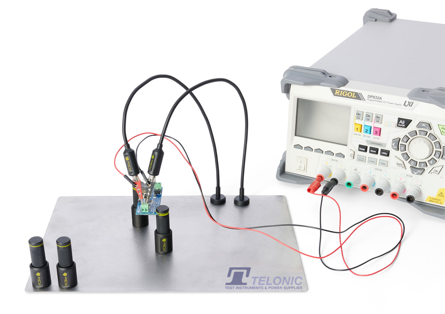
for more hands free measurements I use Sensepeek 4011 PCBite 2x SP10 Probe set
https://telonic.co.uk/product/4012-sensepeek-pcbite-kit-with-2-x-sp10-probes-for-dmm/
they are not high voltage rated because of the exposed metal and relatively thin insulation on the wires but they stay in place. The tips are as sharp and fine as the probe master. They also sell scope probes:
-
 1
1
-
-
1 hour ago, demonkuro said:
Finally found the cause of the explosion.The cutouts in the radiator are slightly crooked, and despite the fact that I used insulation pads and insulation gaskets, they unbelievably caused a short circuit. Silicone pads have no problem with their insulating properties, but they are too thin and can create physical contact in some extreme cases. I have replaced them with ceramic insulation pads and what are indeed much safer. This is an important lesson for me. However, it is good to find the cause of the problem.
im glad you are making progress. checking for shorts from metal tabs on transistors to L bracket/heatsink should be part of a standard test procedure. I personally like aluminium oxide insulation pads... not as cheap as silicon but much more resistance to puncture.. .https://www.mouser.co.uk/ProductDetail/532-4171G
-
1
-
-
1 hour ago, audiostar said:
Before you go deep into the rabbit hole with insulation testing, first you check extremely careful all connections through the umbilicals to the amp boards by continuity. Then you load test the PSU with some resistors, do insulation testing and all the other fancy things.
yep I highly agree.. do the simple things first.... miss-wired psu to amp lead or mis-wired chassis sockets is far more likely than leaking insulation.
-
I am sorry for your loss. Its difficult to evaluate what could have gone wrong, if the psu worked without being connected to the amp then the possibilities are bad wiring between psu and amp board(s) or an issue with the amp board(s)...
generally it is a high risk strategy to power up the entre amp to full voltages immediately...
during building I hand measure *every* component to make sure it is what I think it is. I have once received different transistors from what I ordered (from a reputable supplier) in bags marked with the components I thought I was getting... turned out to be a picking error... Putting them through a component tester alerted me to the fact they were not what I was expecting.
I use an insulation tester to verify there is no leakage between wires within the cable(s) that go from psu to amp. I use a pat tester to verify no leakage from transformer(s) to the psu case no leakage primary to secondary within the transformer(s).
before power up I check there is no continuity between any metal tab on the transistors and the L brackets that connect to the heatsinks. I also check the ground wiring very carefully to make sure the amp pcb(s) amp pcbs share a common ground point with all the psu pcb(s)
after that I connect the psu to one amp channel only (if possible) and check for continuity between each voltage rail on the psu and the appropriate voltage input on the amp board. This makes sure the wiring to the psu socket, the cable from psu to amp and amp socket to amp pcb is correct. I then do the same for the other amp channel. If the amp connects a voltage rail to the heaters of a valve, I also check for continuity between that voltage rail and the appropriate pins of the valve socket.
I prefer to test the psu by itself and run it for several hours not connected to an amp. I bring the psu up slowly on a variac and monitor output voltages and their drift over time. I also use a thermal probe and (carefully) check for overheating components.
When possible I power test up one amp channel at a time (again with the psu on a variac) and monitoring voltages on the amp board as I slowly increase the voltage to the transformers. If I don't see all the voltages increasing at about the same rate I abort because a voltage rail is being too heavily loaded - probably by a short.. If I hear the variac buzzing loudly I have a short and abort. I also monitor DC offset and DC ballance on the amp audio output.
If this goes well I leave the channel for an hour or so again periodically monitoring voltages, temperatures and DC offset, ballance etc. I then power down, disconnect that channel and test the other amp channel (if possible) before testing both amp channels at the same time.
After a few hours powered up I proceed to sine wave testing using a signal generator and monitoring using an oscilloscope. Connecting headphones does not happen until I am very sure the am is stable and reliable.
Its much slower this way but provides more opportunity for catching a fault early and less damage if a fault does occur.
-
2
-
-
57 minutes ago, arcanaking said:
Thanks jamesmking.
This is my transformer's information. It is a 50VA 25V toroidal transformer. I shorted the red (25v) and orange (0v) and connected to the gnd. Thus, it will perform 50v output when the probes are on the left and right pad in input socket.
I have tested the voltage reference as the guide, the positive side is 10v in stable. Yet, the negative side starts with 10v and drops quickly.
Most of the parts are from mouser. Only some DN2540N3-G, MJW21193G and MJE15030G are ordered in Element14 because mouser has no stock currently.
mouser and element14 are both reputable suppliers. Your connections to the centre tap input on the grlv is correct
.
please check the ac voltage from the centre tap to each of the ac voltage inputs. I.e. multimeter from ct (red and orange wire) to the black wire and multimeter probes from ct to yellow wire. This will check your transformer is ok
then check the dc voltage across the plus and minus terminals of each of the large input caps. this will check your bridge head rectifier diodes are ok
also please take a photo of the underside of the board. If you have a dry joint its possible to get behaviour where you initially get some voltage and then it drops away.
-
8 hours ago, arcanaking said:
Hi All, I am building the GRLV 2018 version.48 and I get a problem which I have no idea to tackle it. Before I soldering all the parts, I checked the position of ksp92 and ksp42 and confirmed they are put in the correct position. When I plug the 50VA transformer to provide double rails 25v to the GRLV, all the LED will light up but only the LED which near the zener on right side will dim soon.
I use the multimeter to check the output voltage and I found that the positive rail provide stable 20v but the negative rail will keep dropping the voltage every second from 20v.
Can anyone tell me why the negative rail keep dropping voltage? Do I mess up the polarity or put the component in a wrong place and thus lead to this problem?
1. check your transformer, you need a centre tapped secondary and make sure the centre tap is going to the CT terminal. If you wire the transformer to the grlv incorrectly you can can one rail working and the other not.
2. measure the ac voltage going into the board (centre tap to one ACV input and then centre tap to the other) to make sure the AC voltage is about the same on both.
3. check the voltage references are outputting 10V
4. carefully check the underside for solder bridges and dry joints.
5. are all the transistors, opamps and voltage refs from reliable suppliers and not off ali express or ebay? - there are lots and lots of fake parts floating around...
here is a link to my build and troubleshooting guide:
https://www.head-case.org/forums/topic/12269-goldenreference-low-voltage-power-supply/page/27/
-
1
-
-
12 minutes ago, jokerman777 said:
Thanks, it shows back-ordered again on the UK site now, back to living with 5027s
😬 either someone just purchased almost 2K in one go or the stock notification I got was an error, or the shipment to farnell got hijacked 😞
digikey still says expected stock around 26th june...
-
16 minutes ago, jokerman777 said:
Tried to order some but seems like they don't deliver to US address 😑
in USA the company is called newark rather than farnell:
https://www.newark.com/onsemi/ksc5026mos/trans-npn-800v-1-5a-150deg-c-20w/dp/50H4689?ost=ksc5026mos
is the USA link to the same.
-
the ksc5026mos is back in stock at farnell
almost 2K in stock at the moment
-
1
-
-
1 hour ago, Satyrnine said:
MJF15031 from mouser: All around 280hfe +/- 5.
MJF15030 from THIS ebay seller: 80-150hfe. Oof.
Visually they look identical, even with a loupe. I know that doesn't nec. mean much. Is this normal? If these are questionable, anyone have a source for 30's?
almost no authorized seller except farnell has MJF15030G in stock at the moment.
Farnell has 347 https://uk.farnell.com/on-semiconductor/mjf15030g/transistor-npn-150v-8a-to220fp/dp/9556303
meanwhile the nonauthorized sellers claim to have about 300000 in total between them - I call BS...
using a atlas dca75 pro I get hfe values of 89, 79, 87, 87, 95, 91, 98, 75, 108 for the 9 in my current stock (from radio spares, all purchased at the same time) - known good and used in GRLV. test conditions are: Ic 5mA, VBE 0.675V IB 5mA NPN silicon BJT. Spec sheet says 40hfe minimum for sensible currents.. no range or max is given....
My MJF15031 (from mouser) measure much higher hfes than the MJF15030. hfe 265, 263,264, 270, 263, 265,265, 269, 264, 266. So im getting a similar difference in hfe between the 30s and 31s as you are and a similar spread of hfes.
-
1
-
-
Happy birthday Kevin. Enjoy some: 🎂
You share a birthday with Samuel Morse inventor of the telegraph, Ulysses S. Grant, Sheila Scott (first woman to fly solo around the world) and of course Casey kasem (the voice of Shaggy and Scooby-doo)
-
1
-
-
14 hours ago, kevin gilmore said:
so i posted this elsewhere because people really want to spend large amounts of money on an electrostatic amplifier that uses a pile of 300b.
this is the first of two.
Megatron xl with 4 x 300b
Megatron xxl with 8 x 300b
Will the stn9360 still be ok as a substitute for the 2sa1968?... it would be nice for the megatron 300B to use in production parts...
-
54 minutes ago, jokerman777 said:
Thanks for the advice! My mouser updates tell me that (which is probably not new info):
STN9360 a batch of production is done and is on the way to warehouse now so I guess they will be back in stock soonish.
10M90S says production in process so despite long wait time probably will come back.
KSC5026M it says "Production Issues Reported - Delivery Unknown" which doesn't look good 😅
I wonder if I can do 2SC3840 instead? it's in the PSU and for no reason and understanding I thought I need to either use 2SC3840/2SA1486 or KSC5026M/KSA1156 in complimentary pairs... but since 2SC3840/KSA1156 is what I can get realistically...
btw I think I'm going to use STP8NK80ZFP instead of the obsolete FQPF8N80C, at a glance the specs looks very similar other than a different Id rating and speed.
FQPF8N80C is still available from radio spares: https://uk.rs-online.com/web/p/mosfets/1454316 and https://uk.rs-online.com/web/p/mosfets/6715326 and https://uk.rs-online.com/web/p/mosfets/6715326P
KSC5027 might be an alternative to KSC5026 in the longer term - different package TO-220, higher current and wattage BUT different pinout
-
1
-
-
7 hours ago, jokerman777 said:
New to ES headphones and am currently waiting on these back ordered parts to build a KGSSHV, trying my luck here in case if someone knows any reliable source having them in stock or has spare ones to get rid of.
")
4 x STN93603 x IXCP10M90S (TO220)
4 x KSC5026M
radio spares and farnell has STN9360
IXCP10M90S and KSC5026M have been out of stock for a while and look to be out of stock for sometime. 😞
-
20 hours ago, Urs said:
Dear all,
I’m currently considering to up-dating my STAX-compatible HeadAmp with an extra-option of a variable Polarization Voltage .
Reportedly, the SR-007 Mk2 may benefit from such a higher voltage
Who has experience with such a feature ?
Thanks & Regards
Urs
if you make the bias voltage too high there will be a spark from the diaphragm to one of the audio grids. This will burn holes in the diaphragm and result in a very costly strip down and repair not to mention the possibility of damaging the Stax amp. Stax choose 580V bias for a reason it works and is reliable.


The ultimate DIY? A Stax SRM-T2!
in Do It Yourself
Posted · Edited by jamesmking
RIP MY T2
ever had a day when everything goes wrong and you wished you had not got out of bed....
well I just wrecked my T2. Don't have the energy or will power to even troubleshoot it...
what happened.
I was slowly over time getting a DC offset on both channels, I would correct with the trim pot until I ran out of travel. My first thought was the valves were getting old. Yesterday I decided to open up on the amp case and check the virtual batteries and voltages.... Well the -560V rail was -600V... I spent most of yesterday looking for shorts, diode checking the transistors and doing the usual troube shooting. Since the psu was basically working but not regulating the -560V I also looked a live voltages... To cut a long story short I discovered partly by logic and partly by accident that even maxing out the trim pot only gave me -9.6V on the 20K resistor on the voltage set string. The voltage reference was correctly outputting 10V. I checked the trimmer and it would change in resistance over its travel. So my conclusion was with the two 540K resistors had drifted up in value and therefore reducing the voltage across the 20K resistor or else something was stealing voltage from the 20K resistor...
today I did more testing and desoldered one end of each of the 540K resistors and measured them... 580K and 700K... I remembered that I had replaced all the voltage set resistors with TE 0.1% 1/4W a while ago... I checked the spec sheet and they are rated at 250V.. too little for the job and I think this is what caused them to drift high. My guess is the 700K resistor started to drift high, got more voltage drop across it which naturally increased the drift. I replaced them with Xicon 1/2W 1% 350V and for the -560V rail immediately started regulating again.
job done back to listening right.... RIGHT....????
After some testing I connected the psu back to the T2 and the led on both channels close to the -260V terminal did no light. But with no load the -260V rail was rock solid. Connected to a T2 the rail only provided +75V on top of the -560V rail rather than the +300V it was designed to give. I guessed the 2N3904 in the -260V rail had spontaneously decided to fail in the current limiter and so decided to replace it. The 2N3904 I desoldered measured on a peak dca75 as shorted so I was sure I had found the fixed the problem....
again testing without a load everything seemed fine.
So back to listening now... right... well...
Then I did something really stupid. I thought the psu was off and connected the high voltage cable from the psu to the amp (the low voltage cable with the heater supplies was not connected) there was immediately sparking noises and I quickly turned off the psu.
I tested the psu without load - all rails seemed good.
I connected the psu to the T2 and powered it up. All the voltage rails where at the correct levels on the T2 But I had massive ballance issues between the + and - halves effecting both channels. All 4 virtual batteries now only read about 550V, (all the leds light so that's something)...
SH*T SH*T SH*T DAMN DAMN
I guess next step is to test all the valves, take the amp apart and hope the 2SK216 and 2sj79 are ok.
I have one complete set of spare 2SK216 and 2sj79 and do have a spare set of amp pcbs so I am debating if it might be simpler just to build a new set of amp boards rather than try to troubleshoot and salvage what I have.
today I simply should not have got out of bed.