


palchiu
-
Posts
118 -
Joined
-
Last visited
Content Type
Profiles
Forums
Events
Posts posted by palchiu
-
-
On 3/22/2019 at 10:05 AM, palchiu said:
PIease add me for 1 set of mini T2(2, 1, 1, ,1, 1) thanks!
Please update to 4,2,2,2,1 (2 sets PSU & 1 set mini T2)
Thank you!
-
PIease add me for 1 set of mini T2(2, 1, 1, ,1, 1) thanks!
-
About SS Dynalo Mini, after adjust properly then soldering servo opamp?
-
fees and tax paid.
-
Paid, and thank you!!!
Paid again. sorry I forget add PP fee.
-
4 hours ago, JoaMat said:
May I help?
Q1/Q3/Q13 - MMBTA56
Q2/Q4/Q14 - MMBTA06
JoaMat, thank you!!!
-
Kerry,
What are these trasistors Q1~4/Q13/Q14 you recommand to uesd ?
Thanks for you sharing your beautiful dynalo to us.
Pal
-
Spreadsheet is locked. May MLA help to unlock it?
-
Should be alpha's pot. there. GB boards with pots?
Is that possible to modify another version to fit mulitple kind of pots? like 4CP601/2500 RK27 as Pot PCB GB's version? Maybe board will longer but more options to fit volume pots.
-
On 2016/5/5 at 9:47 AM, DonAudio said:
I purchased a megatron board and power supply board from Joachim. I believe I have a complete list of the parts necessary to build except for the following. I was wondering if anyone would be able to guide me to an appropriate source for these items. Any help would be appreciated:
Qty Value Ea Schematic X-Ref 12 2sc4686a 1.4 16.8 Q1-4, Q9-10 4 2sa1968 0.7 2.8 either this 4 ixtp01n100d 1.29 5.16 or this 4 2sa1486 1.86 7.44 Q15-16 4 2sc2705 0.46 1.84 Q11-12 4 2sc2240 0.38 1.52 Q13-14 4 2sa970 0.38 1.52 Q17-18 2 LSK389 10 20 Q19,Q22 2 2SC1815 0.19 0.38 Q20 2 OP27GPZ 1.93 3.86 U2, 6 2 2sc3675 1.22 2.44 Q5, 15 This should be KGSSHV's BOM
-
sorenb, thank you!
-
Single Skinny PS is this version? -> kgsshvpssicfetsinglenewleft.zip
-
On 2016/1/3 at 4:30 AM, kevin gilmore said:
About 300 ohms is the right number, don't know if that's total or just the tail resistor. Less ohms in the pot and most in the resistor is what we are aiming for.
zener needs to change to 18v
Dear KG,
I'm working Ground Grid's BOM, Zener should be 18V or stay 12V that label on board?
Thank you!
-
Thanks Kevin! I'll try other viewers.
-
Incorrect when open some files with DFN Now V7, not every files only few.
Is wrong setting in DFM?
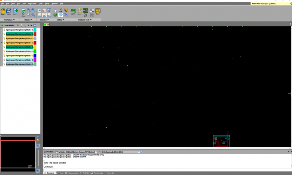
Thanks your help.
-
 1
1
-
-
How about Hammond's enclosures? 1455/1457 series?
-
3 minutes ago, Kerry said:
I've been meaning to get to this for the last year or so. I was motivated to see if I could get this down in size
")
The current board is 4.8" x 6.8" and is an all in one. Everything from power inlet to outputs.
I still have a few things I'd like to get to, including having an option for the regulators to be off-board as well. I'm using some Mean Well switchers at 24V for the +/- rails then using the TPS7A4700 / TPS7A33 for a second stage regulation down to +/- 20V. These regulators have 4uV / 16uV noise respectively (not bad).
There's a switch in front that allows you to change between SE and Balanced inputs via some relays.
Here are some pics of where it stands so far...
It's awesome!!!
-
Beautiful!
-
Beautiful!
-
5 hours ago, Pars said:
Did you have a particular SMD cap package in mind? Let me know and I will add it.
6032 for 10uF maybe easier, but 47uF only 7343 package maybe more difficult?
-
I saw a smd version from China.

-
Is possible add smd type soldering pad at GR LV's backside? smd tantalum capacitor looks are cheaper and easy to source.
maybe just my stupid idea.
 On 2016/1/30 at 2:25 AM, Pars said:
I had mentioned using Schottky rectifiers for this. I think I am going to have a few of these made:

These are setup to take either a D201 axial diode (31DQ10 or equivalent), or also accept a TO220 package like an MUR820. I know the TO220s should probably be oriented 90 degrees from how I have them for airflow, but my intent was the axial Schottky diodes on these.
I home-etched a pair of these and used them in my original Dynalo (headamp board). I used some Mill-Max right angle pins on those (3301-2-14-21-00-00-08-0), and plugged them right into the RS402 bridge holes on the PCB. If anyone with appropriate facilities wanted to compare these noise-wise to the packaged rectifiers, I could send them a pair to test.

EDIT: Added John Swenson snubber across AC primary
Love this board!
-
Oki PS-900 +1 best entry soldering station I've used.
-
10 hours ago, Kerry said:
nicely done. Where did you get the case?
Similar like this


Kerry Design mini GRHV\GRLV and JoaMat mini T2 Group Buy
in Do It Yourself
Posted
Payment sent. Thank you!