

fishski13
-
Posts
149 -
Joined
-
Last visited
Content Type
Profiles
Forums
Events
Posts posted by fishski13
-
-
strapped on a new pair of Voler bibs for a 1hr on the rollers today. my longest ride this summer was only 50mi and my butt felt reasonably fine in the saddle. with a single speed you're going to spend more time out of the saddle in general to attack the hills, but with rollers i spend much more time in the saddle and needed a pair of padded cycling shorts. i can ride out of the saddle for short periods but it still feels a bit sketchy. getting proficient on rollers takes some time. learning to ride one handed or even turn your head to the side without ending rubber up takes practice. i wish i could find the youtube video of a guy snorting rails of coke while playing tennis on a Nintendo Wii.
with a googled 15% off promo code these Voler bibs came in at just over $75, just enough to qualify for free shipping: http://voler.com/browse/product/li/1110521 . the fit is true. stitching and construction is excellent.
-
i just discovered this great thread. lots of helpful info for someone like myself just getting back into bicycling.
i picked up a Wabi Classic for my b-day last July. steel frame and cuts the pavement like butter at 110psi. a flip-flop hub, riding SS, and 46/16t gear. the only components i want to replace are the tires, seat post and ass hatchet. a cadence meter would be swell as well.
i've put 500+mi on it plus a few hours a week on the rollers. i don't have much climbing on the local roads/trails here in my suburban enclave. i have access literally in my back yard to the huge Elm Creek paved trail system here in Maple Grove, MN. round trip to my favorite bar is only 10mi.
after numerous adjustments, i think the fit is comfortable. the only thing i need to work out are my shoes and cleat positioning. i initially bought my Giro Privateers one size too small. thankfully REI was cool enough to allow me to exchange them (i know many members abuse their generous return policy). my feet are not equal in size and i've been playing around with various sole inserts and sock combos.
going for a ride clears the mind of all the day to day bullshit. i feel like a kid again.

-
match NPN to NPN and PNP to PNP per board. i was able to basically get identical matches with the MPSW06/56 for each board. i bought 100 pieces each since they're cheap. i think 1-2% variance in hfe would be fine. for the MJE15030/31, within 5% is good. i would recommend buying 2x more than you need.
if you don't match the sand, you could have significant differences in bias across each of the devices. you need to measure across each and every one of the 20R resistor pairs to make sure all of the output devices are biased reasonably close to one another. you don't want one biased at 50mA and another cooking at 90mA.in my chassis, i was able to get the bias to 42-43mA per output device with a reasonable junction temp. -
G600,
you need to match the transistors. i would just rip out all the sand and make the effort to match them.
in my mancave, the on-board heat sinks will do 50mA/500mV per output device, measured across each paralleled 20R pairs, in free air... if you want a safe junction temp - thats around 3W dissipation per 2.5" tall heat sink with BJTs that have positive temp-co properties. depending on chassis ventilation, you may have to go lower.
-
i realized that but went ahead and posted it anyway since other builders may have the same biasing questions.
as to your biasing issues, i have no answers other than you possibly have poorly matched devices or fakes. i would try to re-bias.
-
biasing the SuSy boards:
-before first power up, the pots that flank the THAT340 should be at their mid point. the outer biasing pots should be as follows, when looking at the board with the heat sinks at the rear: L - fully CCW and R - fully CW. leave the DC servo opamp out.-bring up the bias by turning the L outer biasing pot CW and the R CCW, keeping tabs on the DC offset. both pots will increase the quiescent current bias, but also affect the amount of DC offset. i just turn them in equal amounts until i hit my target quiescent current and then tweak for lowest DC offset. the offset will fluctuate quite a bit, like 100mV. small fractions of turns on the pots will cause the off set to jump. be patient. i think the best i could do was roughly +70mV to -30mV.-insert the DC servo. measure the offset between the O(+) and O(-) - i measured 20 and 25mV. turn one of the THAT340 pots CW and the other CCW, 1/2 turn each. note if the DC offset went up or down. if it went down, then continue turning the pots in the same manner, in 1/2 turn increments, until you reach 0mV. if the offset went up, then reverse the turns in the opposite directions.-i was able to get less than 0.5mV offset and very stable. on cold start up, still a very low 2mV. zero pops or hiccups through my HPs either on power up or power down.-
 1
1
-
-
mucho gracias!
-
congrats. enjoy.
-
most awesomest translation.
-
If its any help (or not) I really like the CKK-III as a project for further down the road.
On many levels its a shame that it gets passed over for the b22 so often.
agreed. can drive drive any sensible HP without issue and sounds fantasic. don't skimp on pot/SA. silly cheap and an amp that sounds good with every thing.
-
thanks! TXs are inductive:) the Bulgin latching power switches i use are rated only for 3A. i wire in a 10A mechanical relay to take the brunt of the inrush current. the only SSRs i've seen are spendy too.
-
Cool
 So I am down to only one beef with amb.org. Recommending SSRs. I am going to put a community service project out to remedy this soon.
i'm not SSR savy - only seen one in a B3 DAC repair i performed. what's your primary beef?
-
Marc, copy and paste.
Notes about R34 and R35:
The default value for these resistors is 0.47Ω. If you have TRS headphone output jacks, the value may be increased to 1&Omega to 2.2Ω for added protection. This is because TRS plugs create momentary short circuits while being inserted or removed, and could potentially damage the output MOSFETs.
On 4-channel balanced configurations with only XLR output jacks, or if the amplifier is for speaker use only, it is not necessary to increase the value of these resistors.
The drawback of increasing these resistors' value is a small loss of maximum output voltage swing capability.
If you use the default 0.47Ω value with TRS jacks, it is recommended that you turn off the amplifier before inserting/removing the headphones plug. Or, at the very least, turn the volume to minimum and insert/remove the headphone plug very quickly.
Metal oxide resistors are the only recommended resistor type for R34 and R35. In particular, do not use wirewound types. Also, do not use resistors rated higher than 2W. -
i've never had an issue with my B22 in 5 years, even with 0.47R Source resistors. i think most builders are opting to increase the resistance to 1-2.2R to provide a larger margin of safety against shorts.
-
... The B22 is fragile so be prepared to to some error checking which is arguably the hardest part of DIY.
not recommended for a first time DIY project, but i wouldn't call it "fragile".
-
congrats!
i tried the Alps, TKD and GoldPoint in this amp. my favorite was the GP, but i could live with the Alps.
yes, a big thanks to KG, Bigir, and Lil Knight for making this project possible!
-
I'm getting close to the point where I'm able to power up the amp. I've got the trim pots set in the middle (250Ohmz).....any idea how close centered is to the desired bias point? I'm assuming 125mv cold is across the 2ohm output resistor test points.
Btw there is an ebay unit up for sale again....2999..
you could take the trimpots down a bit more, counterclockwise a few more turns, assuming you have them soldered in correctly. i started half way and measured about 350mV across the 2R emitter resistors.
-
thanks. TRS ground is soldered through-hole on the underside of the G-pad on the PS (plenty of room to insert 20awg along with the terminal pin), and yes, ground to chassis is a ground loop breaker with a 5W 10R wirewound and 0.1uF 250VAC Type X in parallel.
-
swapped out the RK27 for a TKD 2CP-2511. preferred the Alps with my Belden screened ICs but coming around to the TKD with some Mogami ICs. just need to finalize the FPE design. here's a badge i'm tweaking at the moment. haven't decided on button-heads or socket-heads. hole is for an illuminated latching Bulgin switch.
http://i23.photobucket.com/albums/b353/fishski13/krellbadge1_zps176452fb.jpg
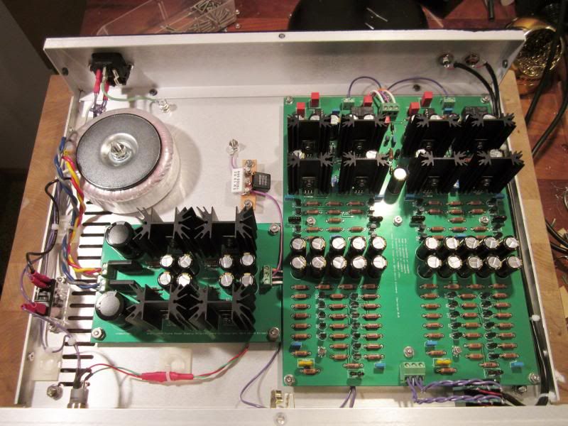
amp board standoffs are 3/8 and the PS board 1/4 to allow easy routing/securing of wires a distance away from the bottom of the PCB. very,very quiet even with the sensitive AD2000 up to 4-5 o'clock. i bet an encapsulated TX would get you a few dB or of noise attenuation, but any noise is still 6hrs or so past sane volume levels and a 2Vrms source. dead silent with both the K701 and T50RP throughout full volume sweep.
http://i23.photobucket.com/albums/b353/fishski13/012_zpsdfd46a29.jpg
-
Sweet! Almost done collecting parts here....just need a few more and the boards to come in from Lil' Knight and I'm building.
What value Pot did you end up using?
I'm going to use Amphenol military PT06A84 as the connectors for the umbilical....but then considered trying Neutrik RJ45 connectors.
Looks like they can handle the load and would be very tidy. Thoughts?
if i go with a loop-out, it will be a 25K pot, otherwise 10K if no loop-out. i'm going to call Parts Connexion to see if they have any TKDs in stock while the 20% sale is on, otherwise i'll just go with a Goldpoint.
the Amphenol Econo-Mate are nice, but physically big. i really like these from JAE Electronics as well - http://jae-connectors.com/en/pdf/2008-96-97-SRCN.pdf .
Par-Metal sent me a a lid with paint drippings. they're sending me a new lid, but may end up going with a Lansing chassis instead, so no chassis work until i get this sorted. Par-Metal is another 6 mo. out from doing any anodizing since the fire.
i didn't do any BJT matching, but without the opamps installed, i get 16mV and 120mV DC offset. with the opamps installed, i get 0.6mV and 2.4mV respectively.
-
planked the amp out with a Blue Velvet. sounds excellent even with a cheap pot. some noise beyond sane listening levels with the 102dB AD2000 and 103dB D2000, and basically dead silent until the last hour or so on the pot with the 93dB K701, but a rats nest of wiring right now. can't wait to get it in a chassis with a TKD or GP.
if my maths are correct, the gain is 5x?
-
the TX is from SumR.
above maths is just the quiescent current draw. anybody have an approx total current draw per channel?
-
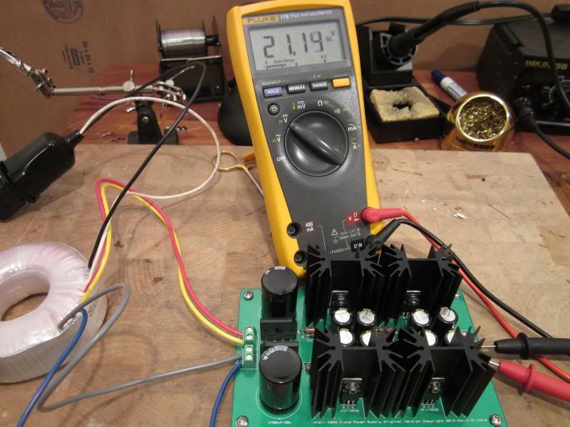
fired up the PS: http://i23.photobucket.com/albums/b353/fishski13/002_zps0d93dd0f.jpg
SumR 27V x 27V/50VA = 21.1V output unloaded
Secondaries = 32.3V
Collector Q1,Q2 = 42.5V
Collector Q3,Q4 = 27.5V
can i assume that when loaded, the V across the BJTs will drop a bit? with the above numbers, assuming a total current draw of 400mA and power dissipation of 200mA on each rail, i'm looking at 3W on Q1,Q2 and 1.3W on Q3,Q4. should be fine with 2" heatsinks and a little thermal grease with adequate ventilation.
-
great.
i went ahead and ordered a SumR 2 x 27V/50VA at $54.
 So I am down to only one beef with amb.org. Recommending SSRs. I am going to put a community service project out to remedy this soon.
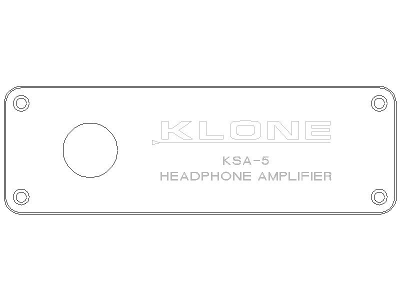
HC Bike/Cycling Thread
in Miscellaneous
Posted
Ben's Cycle is having a %15 off holiday sale. decided it was time to get ride of the sagging stock Wabi saddle and picked up a San Marco Rolls: https://www.benscycle.com/p-3557-san-marco-rolls-miele-saddle-tan-steel-rail.aspx . i'm buying blind but both the Rolls and Regal seem to be universally liked by most asses.