joeBerlin
-
Posts
5 -
Joined
-
Last visited
Content Type
Profiles
Forums
Events
Everything posted by joeBerlin
-
I try to build Kevin Gilmore's Blue Hawaii Amp
joeBerlin replied to joeBerlin's topic in Do It Yourself
Now (2 years later) I found some time for the project, but... Module 1: has SJ79-trouble - 2 sets went off in smoke, obviously in the power up phase. Maybe during power up + and - behave somehow differently or whatever, at least I think I have to deal with the situation that somehow more than the allowd 200V U_DS (with the 15 mA limited current) can occur. As protection I thougt of 1) 2* 1N53718 60V Zeners (20 mA Iz-test, the 120V Version has only 10mA) parallel D--S and 2) some Rv for the Gate. In the SJ79 specs the biggest C I found was 120pF without fully understanding it. Anyway: Even if that one counts and if I take Rv=100k I get RC=120E-12*100E3 sek=12E-6 sek which is hopefully far enough from audible stuff. On the other hand, if U_GS becomes for whatever reason so that, say, 500V is on Rv I get 5 mA which hopefully can be handled by the built in G-to-S Zenerdiodes. Imho for that reason the usual small values in the 100R range wouldn't make to much sense im my case. Module 2 amplifies the Input, but 1) only if I reduce UV to +/-300 V. U(Gate 2SK216) is only 12 V over the minus rail. Current is 2x 1.88mA in the Vbe multiplier. What to do? Change R's in Vbe multiplier or change th 2 k pot to 1 k? and 2) it swings up with 4 kHz, which changes if i touch the 2SK216 gate with a grounded 5pF condensator. Now I have A--G1 220pF and A--Gate(2SK216) 33pF. Both C's have obviously something to to with negative feedback in unwanted freq's - is there a technical term or articel for all that tube/C stuff to get a starting point for better understanding? -
I try to build Kevin Gilmore's Blue Hawaii Amp
joeBerlin replied to joeBerlin's topic in Do It Yourself
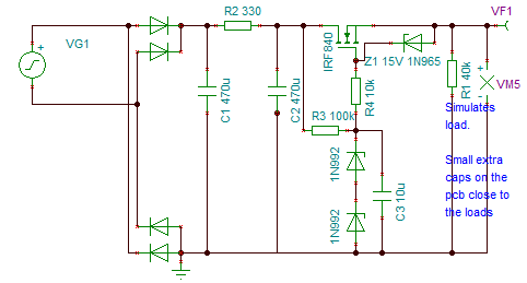
Meanwhile the 1st order for parts is out, as transformer for HV I found only a 2x350V centerd one, (Hammond 373DX, which has also the advantage of 200, 210, 220, 230, 240V primary connectors, we have 230V, so some freedom is left for fine tuning the secondary voltage). Anyway, now I must reguate V- too. To my oppinion this should work with the 600V IXTH10P60 (I orderd 3 if somethind goes wrong a the first place). On then same order I put 4x 150uF film caps (47 EUR each). I think about a C--R--C--MOSFET--small_C_at_Load arrangement. Is that ok? Some people recommend fast diodes for the rectifier, wrapped with R/C arrangement (see schematic and comment in there), how can that be seen? Improvement BS/possible/audible/measurable? What about the diodes? I ordered (also for the bias) HER108 with 1000V, 75 nS revovery time @ IF 0,5A, IR 1,0 A, IRR 0,25A anyway, 1000 V is quite close. Better to connect always 2 in a series (they have peak reverse current 5/ 100uA @ 25/100 °C so with 2xR 1M as voltage divider parallel)? As alternative I ordered also BY329-1200 (1200 V, 135 nS) - enough to avoid the series. Are there differences to expect? ...well, I can't upload images for now: so schematic is like in post 1, but mirrored for the negative branch, some details changed (2x 150uF, R3=200k and diodes wrapped like that: --+--10R-->|--+-- where +..+ goes to a 100pF...100nF cap to extinguish spikes, which could occur always @0,7 Volt when the diode switches off "nearly no current in nearly no time" connected to the iductivity of the transformer. -
I try to build Kevin Gilmore's Blue Hawaii Amp
joeBerlin replied to joeBerlin's topic in Do It Yourself
An explanation could be that the 10m90 could have a build in enhancement MOSFET, just because enhancement is more common. When operating the gate pulls/builds the channel close to itself - this MIGHT cause higher capacity than in a depletion type, which closes the channel when working, especially the parts close to the gate. See page 4 here: https://www.fairchildsemi.com/an/AN/AN-9010.pdf At least it's hard to find comparable enhancement types with comparable good Ciss. Enhancement types must be biased for a CSS, in http://www.fetaudio.com/wp-content/uploads/2003/09/Mu-Stage.pdf its described how to do this (see "MOS Matters"). Most things are described with tubes instedt of MOSFETS. -
I try to build Kevin Gilmore's Blue Hawaii Amp
joeBerlin replied to joeBerlin's topic in Do It Yourself
Ok, thx. I phoned mouser, they have some fedex-Germany-agreement so that I can order there. (Otherways one gets a notification "get your stuff from customs", you have to go there, get a waiting-number-ticket, wait 2 hrs...) You think it's worth to implement the mu follower AND 10M90S with a jumper? If only a phase shift in the high freqs is to be expected the answer is "no" for me. I can do that with a FIR filter as well. If mysterious changes in the sense "more stable soundstage", "more relaxing hearing" etc. things are to expect, it could be interesting. -
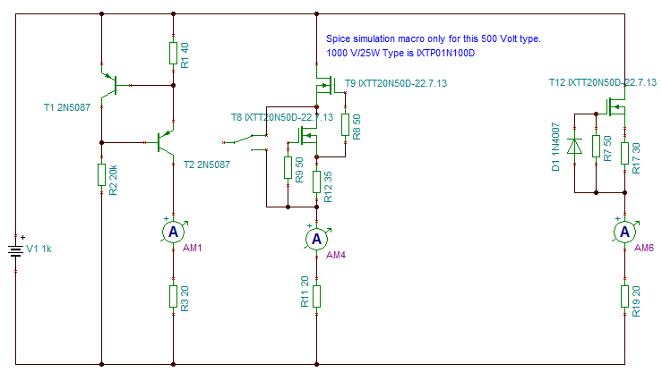
Hopefully I'm at the right place this time. I want to build a kevin gilmore blue hawaii amp. As a starting point I found the original http://headwize.com/?page_id=751 and the more recent http://gilmore.chem.northwestern.edu/BlueHawaii-T2-Servo-v1-2.zip (needs LTSpice). Is there a recent version without servo, with PCB's and all that? CCS is yet partly diskussed, has someone experiance with "mu follower Output" to decouple the complex loads partly from the tubes (see schematic)? What about a PS if no 500V pnp is found? From the PSRR viewpoint I'd start with the concept: "care about higher harmonics, PSRR can start to decrease at a cut-off in the 1 kHz region. And: just in that > 1kHz range, where the measured PSRR comes in, additionally whatsoever interactions between PS and music could come in as well. So starting out with "1 V ripple on the output won't be DIRECTLY audible" could work, but I'd like to have some more safty. So what about a good old plain and simple low-pass with (no 6dB/oct, not L...) R*C*2pi=1Hz first? (Ok, R2 burns some W if some mA is needed, but there is enough space, 150R will do too.)