mahdi8
Returning Member
-
Joined
-
Last visited
Everything posted by mahdi8
-
There is no group order at the moment. Only option is to go to a pcb maker with the design and get your own
-
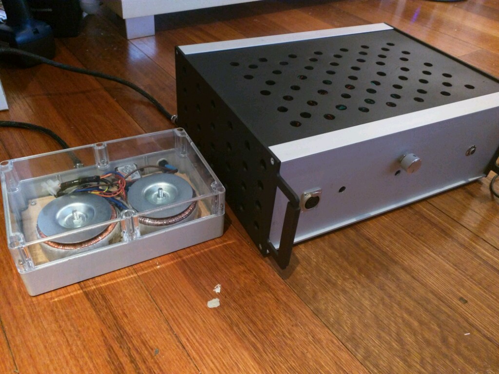
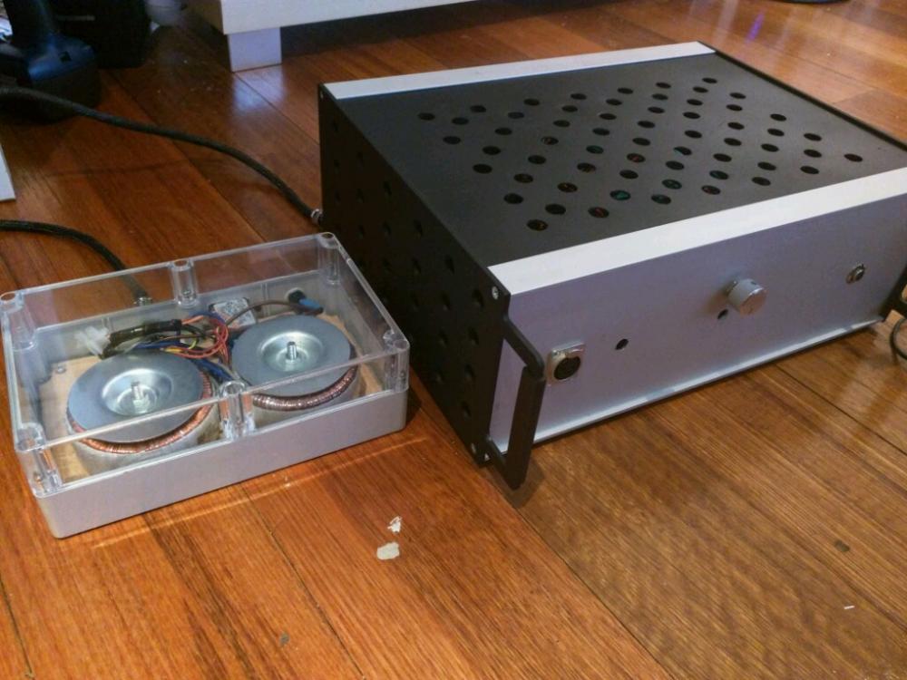
And here is the finished build. By far the most transparent I amp I have ever tried. Kudos to KG its a brilliant design
-
Coming from 70 holes at the top and bottom only which running at a high 82 degrees C. I've drilled much more. Top and bottom now has total of 118 holes and the sides has total of 48 holes. Now the hottest transistor running at 65 degrees C. Pretty happy with that. It was lot of drilling. I almost warped the top and bottom plates from the drilling. Now it's just a matter of resurfacing and repainting the case now. Cos lots of holes on stainles steel look like a cheese grater lols
-
Sounds Brilliant. For me it's as detailed as it's get from any amp. and scales well with better DAC. compared with my old amp moving to a better DAC gives a more noticeable difference using Dynahi
-
I just run it with the bottom case open for now. Most of the heatsink is running under 70 degress only one heatsink is showing 80 degrees. I might adjust the bias again but for now should be all good running it this way. until I have time to redo the case
-
Yikes 323 holes? Don't think I will have the patient to drill that many. I'm considering 3d cutting mdf so i cam easily make lots of holes and painting it for the top part and bottom. Not not sure about the integrity of the mdf after cutting too much holes in it
-
Hi guys I'm finalising my case ventilation. I have put 28 holes with 1.5cm diameter each on the top and bottom of the case and the amp is still running to hot for my liking. I measure the heatsinks is around 85-90 degrees Celsius. That's after the amp running for 2 hours What's the normal heatsink temperature for the on board heatsinkheatsink version? BTW the case has 2 s22 power and 2 amp board.
-
Last time the offset went that high I fried all the npn and pnp transistor
-
Does anyone know where if there is grounding guide write up for the Susy dynahi? Or this b22 grounding guide will work with the dynahi?http://www.amb.org/audio/beta22/wiring.shtml
-
So I'm still trying to figure out where the ground noise is coming from. My setup is 2 case: metal case housing amp and power supply and plastic case housing the transformer. DC power plug, trs jack are isolated from case ground. The volume pot are not isolated from case ground. Should the rca be isolated or connected to the case ground?
-
Referencing you balanced protector board http://gilmore.chem.northwestern.edu/boards/protect3.zipwhich resistor should I change to reduce the trip point to 0.25V?
-
not sure what hennyo style is BTW Looks like a protector board or delay board is really necessary with my build on switch on and off the offset jumps to 1V for 1 second before it stabilize to 10-15mV after 3 second
-
drill away it is
-
Top and bottom? So top only not enough? I'm thinking 20 holes around 6mm possition parallel with the heatsinks would that be enough?
-
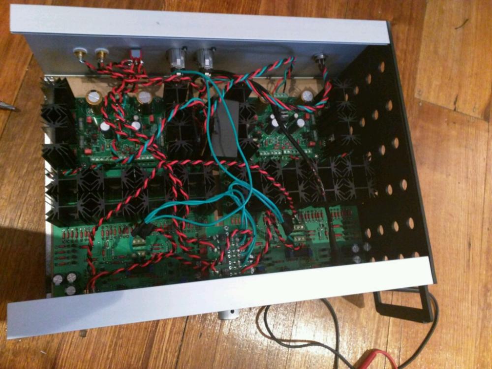
Thanks I'll try that. BTW been using the amp with the case close for an hour it does get quite hot the caae is barely touchable now. The case is sealed full aluminum with no ventilation. Looks like I need to drill holes for ventilation. Or is it okay to leave it as it is. Considering the full aluminum case will act like a big heatsink. The case is 3u rack case but I am putting 2 amp board and 2 sigma22 board in it. Soo its packed. I put the transformer in another case. Will the temperature hike effect the bias and offset? Can't really check it with the case closed
-
To previous builder how hot does your case get. For me get as hot as 50 degrees C
-
Awsome 0.5V protector board would be fine then BTW On single ended I wire signal and ground to + and - of the board. And on the wiring I wire only the signal part to the headphone jack. The ground I took direct from the source ground. Does that sound correct? I was going to wire the ground of the jack to the - of board one. but I think that won't work on balanced input. Or am I wrong?
-
Does that mean anything under .5Volt won't kill a headphone?
-
If I use a protector board the only cut of point is 0.5v. Isn't that too high already? Does anyone know any design that cut off below 0.5v? What is the safe cut off point for headphone?
-
Just worried more on breaking the headphones. But I guess I can put in a protector board. On other note can someone share their wiring diagram on successful single ended out of Susy dynahi? I think my issue is grounding issue.
-
With the servo the offset still drift between 10-20mV is that still fine? I've tried using headphones on balanced the sound is great but on single ended the sound is sucked out especially the mids but strangely low end is fine
-
Finished fixing up my board today. But the best I can bias my board is 0.69v for + side and 0.71 for negative side. The offset without servo is 80mV and 10mV with servo. Is it good enough? Or I still need to get closer to 0.75v and get offset to 0? Any idea which part I need to change? Should I change the 500ohm resistor to something lower?
-
no I'm not that adventurous. So the bias for the onboard version is still 0.75 volt. I replaced the 500ohm next to the trimpot to 680ohm. Because I mistakenly thought the bias should be 75mV. I will change it back to 500ohm now since the bias is now stuck at 400mV. BTW I've read on AMB forum that the on board heatsinkboard should only biased to 375mV because it would be running to hot at 0.75V
-
You meant I can't replace the mje chips without removing heatsink? It's a bit tight for the middle chips but I would have thought it still possible to replace the chip without removing the heatsink
-
Is that even for the on board heatsink version?