


ruslanch
-
Posts
13 -
Joined
-
Last visited
Content Type
Profiles
Forums
Events
Posts posted by ruslanch
-
-
17 hours ago, gepardcv said:
129x99mm
17 hours ago, Pars said:I had tried doing some mods to your layout in KiCad (going back to the RS402 bridges, and adding a Phoenix 508/Molex KK jack that I did in an Eagle library). I was having a hard time figuring out the libraries in KiCad and the schematic image vs. footprint.
I’m using a Mac, so not sure the OpenGL is even an option in that...Something like this: Gerbers, KiCad project, 3D view. Yes, finding the components in the library is sometimes difficult ).
-
14 hours ago, Pars said:
Nice job! KiCad perplexes me, steep learning curve.
Thanks! Initially, I began making a scheme in Eagle CAD and it turned out to be very convenient. But when I started making the PCB layout, then rested in the restrictions of the free version of Eagle, and continued the layout in KiCad. In fact, the difference is small, especially if in KiCad enable the OpenGL mode. The interactive router in KiCad is a bit blunt, it needs a little more tips, but this is a very small drawback. For a new version of the PCB layout, I completely remade it from scratch in KiCad, and now I find KiCad very convenient.
PS. Has slightly updated the project - added a fill of the bottom layer and added 10 ohm resistor for grounds separation.
-
 1
1
-
-
I remade my previous GRLV pcb for my amplifier:
1. Optimized the pcb size.
2. Fixed bugs of the previous version - added forgotten capacitors in the supply chain for op amps, the supply of all internal circuits takes from the pure part of the circuit, as in the original version of the board.
3. Now this is the native KiCad project, not the conversion from Eagle. -
I want to use GRLV for my new headphone amplifier. But I need 30V power supply with 3 sockets, and place for large capacitors in the filter (up to 35mm in diameter), and I want to use Elna Silmic II 220uf, 50V as output capacitors. And I spent two evenings to made my own GRLV pcb, simultaneously learning kicad. This is the first pcb in my life, which I have made myself. I also replaced the diode bridges with the fast diodes MUR820, and shunted them with ceramic capacitors. Perhaps someone will find this useful. But I'm not sure of the complete absence of errors ).
Gerbers: https://drive.google.com/open?id=15m6y5CElB4RjW0pRd9Lu47jA_6w2T-0V
Project: https://drive.google.com/open?id=1bV1xTn5Iw3sC_sxR5AL8iZZ5hN85-95U
-
1
-
-
Can I use opa445 instead of opa134 for GRLV for 30V output? It's necessary? Thanks!
-
On 16.11.2017 at 6:40 PM, kevin gilmore said:
and then things like these for the pins
i'm sure there is a mouser part number, but can't find it
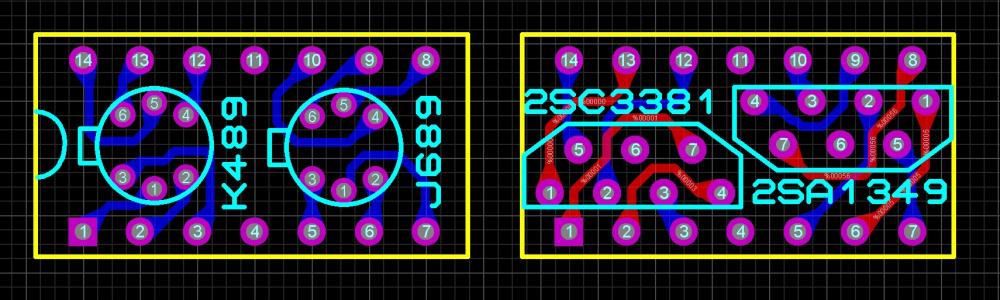
Where can I find gerber for lsk489/lsj689 pcb? Thanks!
-
Can I simply replace the tantalum capacitors with electrolytic capacitors? For example, the Nichicon KL series.
-
8 hours ago, kevin gilmore said:
I was thinking the other board. Yes that board gets that hot due to the transistors
you can add heatsinks
Thank you! I hope that this is indeed so, not my mistake.
8 hours ago, GrindingThud said:Nice!, what heatsink is that on the outputs? I'm so far behind...I still need to build mine. I never found the pot either, is there a source?
Thanks a lot! Heatsinks from the nearest radio parts store, noname ). I bought a pot on ebay. I found a seller with a similar product and asked him to order from the manufacturer for me. It took 3 months but I got what I ordered.
-
7 minutes ago, Helium said:
It might be transistors are heating THAT340 thru copper layers. Are they soldered directy to board, or plugged in sockets?
In sockets
-
4
-
-
16 minutes ago, kevin gilmore said:
that is hotter than I expect, what voltage rails and what voltages on the led's
20v psu , 1.60v on the led's
-
40 minutes ago, Pars said:
I don't think so. Double check all components, check for solder bridges, etc. And this is both THAT340 chips are getting hot? How hot?
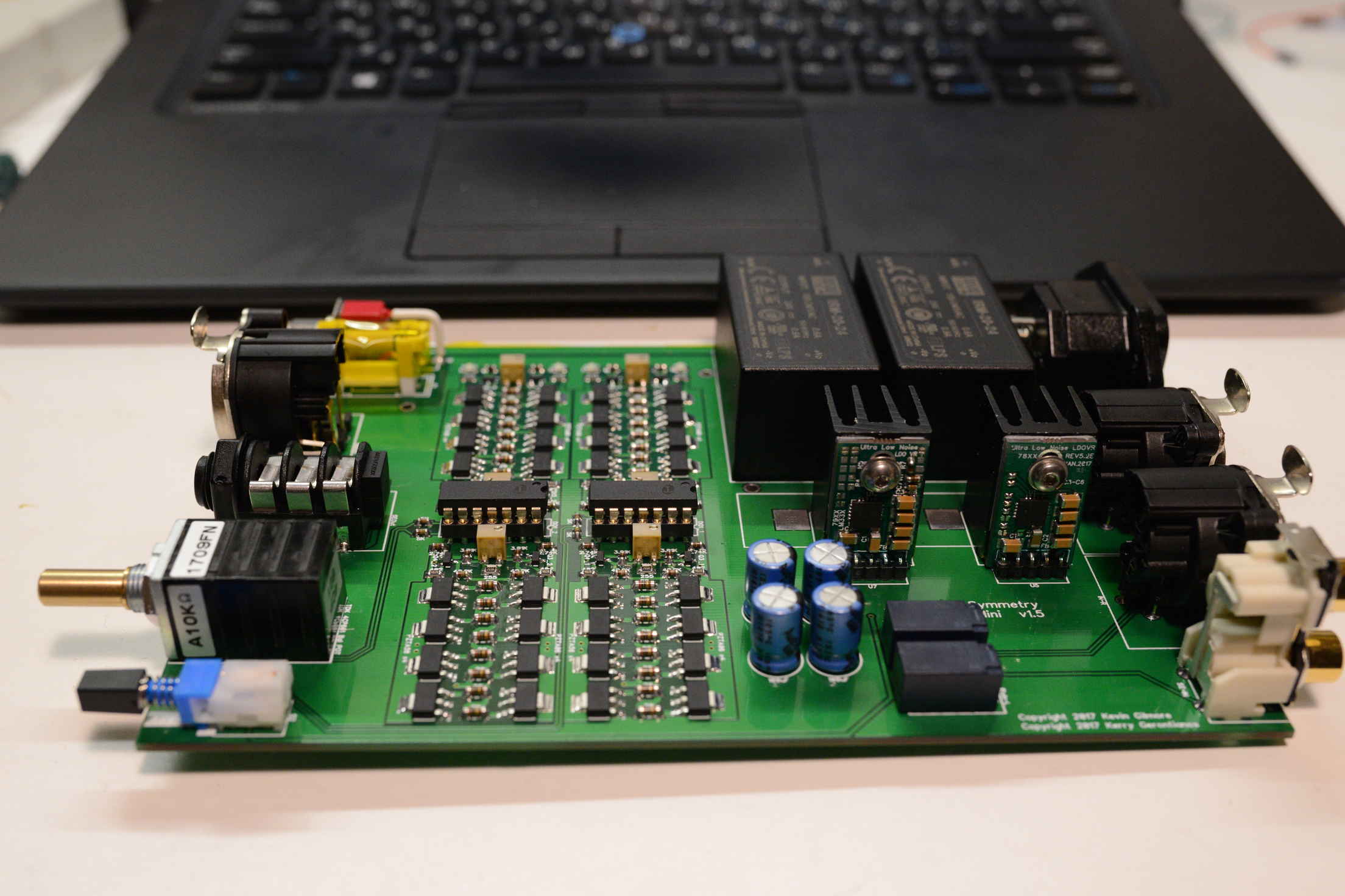
Sent from my iPhone using TapatalkThanks! 65-70°C on that340, both. But works fine. Now I checked all the components of the strapping - it's all right. But hot.
-
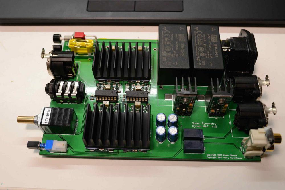
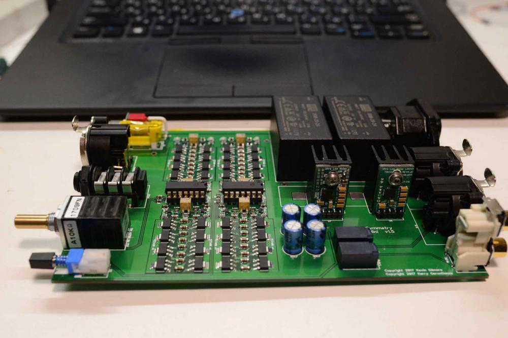
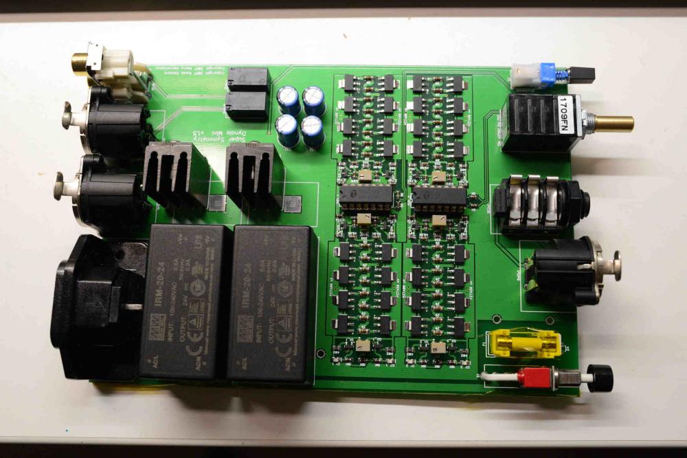
I assembled dynalo mini and that340 chips on my board is very hot. Is it normal? Thanks!


(closed) Dynalo Mini enclosure group buy
in Do It Yourself
Posted
Interested in TKD version!