terminus
Members
-
Joined
-
Last visited
Everything posted by terminus
-
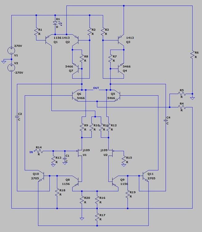
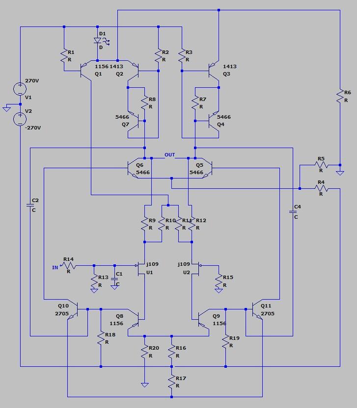
Hi everyone, I’m currently restoring and tuning my Stax SRM-3 electrostatic amplifier and could use some advice regarding DC offset adjustment. So far, I’ve built a capacitance multiplier for the high-voltage power supply rails, and the result has been fantastic — the background is now dead quiet! With the noise floor taken care of, my main focus now is getting the DC offsets properly dialed in. Currently, I am measuring the following DC offsets: - Differential Offset (Stator to Stator): ~6.3V on the Left channel, ~11.2V on the Right channel. - Common-Mode Offset (Stator to Ground): Quite high on both channels relative to ground. I have redrawn the complete amplifier circuit in LTspice (attached below). Please note that I haven't populated the specific resistor values on this schematic draft yet, but the component topology and transistor layout strictly mirror the circuit. I would really appreciate some guidance on where best to insert adjustment potentiometers/trimpots into this topology to allow precise nulling of: 1. Differential offset (balancing L+/L- and R+/R-). 2. Common-mode offset (nulling relative to signal ground). (As a side note: my ultimate plan for this unit is to eliminate the volume potentiometer entirely and feed the amplifier directly via a balanced input. I already have a clear plan for that front-end modification, so right now I’m strictly focusing on getting the core offset adjustment sorted out on this topology). Thanks in advance for any insights or schematic markups!