geremy
-
Posts
18 -
Joined
-
Last visited
geremy's Achievements
Member (2/6)
10
Reputation
-
Stupid M3 questions which I'm sure have been answered before...
geremy replied to geremy's topic in Do It Yourself
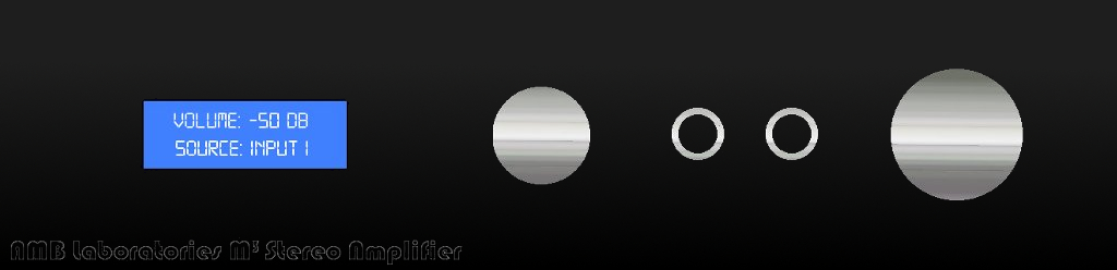
I have attached my projected faceplate design. Inputs are appreciated! I'm not sure whether or not it is OK to use the AMB Laboratories name. Anybody know? Current Plan is for the case to be the Hifi2000 Galaxy GX348 with the optional 10mm front panel. The text is (hopefully) milled out from the plate. The knobs are also from modushop.biz, they are the 29mm for source/power and 39mm for volume/mute. The jacks are standard neutrik. I am considering adding the milled handles if that is possible on the galaxy front panel but I'm worried it may be overdoing it.
-
Stupid M3 questions which I'm sure have been answered before...
geremy replied to geremy's topic in Do It Yourself
Nobody has any thoughts about terminating the 6 inches of copper trace from the unused inputs? Is the question just silly? -
Stupid M3 questions which I'm sure have been answered before...
geremy replied to geremy's topic in Do It Yourself
Actually according the nichicon website there is UKZ1H caps available, rated at 50V. I cannot find them on the mouser site thought. The do have a slimmer temperature range (-40 to 85 C) and are only rated for 1000 hours as opposed to the PW's 3000 hours. Thanks though, I didn't believe that there would be any appreciable difference but I wanted to check. Now I need to find a small +5V linear standby supply for the volume/input kit. I'm thinking about going with the standby supply which Mister X linked me to earlier in the thread here: Standby supplies -
Stupid M3 questions which I'm sure have been answered before...
geremy replied to geremy's topic in Do It Yourself
Almost all the parts are now in and I have some more silly questions: 1) I plan to mount the board in the chassis backwards (volume and bass-boost pots to the rear) to minimize the length of wire from the input selector/volume attenuator kit and also to place the heat sinks closer to the edge of the case where the venting is. This means that I will be using the front board inputs only. When looking at the board, this means that I have about 6" of copper trace antennas on each signal channel. Is there any recommended termination schema? Should I cut the traces to the rear (my front) inputs? 2) For C4, C5 and C7 I ordered from the Nichicon PW line. Do these caps make much of an impact on sound being that they are not in the direct signal path? Should I upgrade these to the KZ or go for some boutique brand? I don't see how they are going to make any difference but I figured I'd ask the experts. Thanks for the help. -
Stupid M3 questions which I'm sure have been answered before...
geremy replied to geremy's topic in Do It Yourself
I like bright. I'm not opposed to rolling but I like the really tight dynamics. Thanks for the link. I already ordered a volume control/remote/input selector kit from bbp at diyaudio. The same one that is in naamanf's b22. Quite inexpensive and only 1 left so I pulled the trigger. It's not that big a deal if it's a bust. I have to say, I have been shopping for a headphone amp for a while, and they DIY route is amazing in the feature/dollar ratio! naamanf's b22: http://www.head-case.org/forums/do-yourself/476-diy-amp-such-build-gallery-87.html#post235506 thread about kit: diyAudio Forums - New project : R-2R Attenuator With Remote Control V2 - Page 1 I will have to do something else about gain control. At the moment I'm thinking i will have to open the top cover to change the gain, which isn't that bad. I have also decided to start with a gain of 5. I know some folks recommend 2, but I have to think that has a lot to do with the source as well. Thanks for all the help! My summer intern is eager to get building. ;-) The vast majority of the parts will be here next week. The only things really left to purchase now are the case, transformer for the sigma-11 and a 5V supply for the volume/input selector kit. I am toying with the idea of peak-meters. Maybe ones that can be switched in and out of the signal path. -
Stupid M3 questions which I'm sure have been answered before...
geremy replied to geremy's topic in Do It Yourself
I graduated from Georgia Tech with a BSEE in 1999. I don't actually believe that it makes a difference, but I'll be the first to admit I don't know everything. Besides, I do mostly digital stuff... -
Stupid M3 questions which I'm sure have been answered before...
geremy replied to geremy's topic in Do It Yourself
Yes. Nothing audio related though. I'm an electrical engineer. I have plenty of standard eutectic solder, but I'm wondering if I the Cardas solder (or equivalent) would represent a significant improvement. -
Stupid M3 questions which I'm sure have been answered before...
geremy replied to geremy's topic in Do It Yourself
I mean the type of solder compound. I have lots of stuff around, just wondering which types are recommended for audio equipment. -
Stupid M3 questions which I'm sure have been answered before...
geremy replied to geremy's topic in Do It Yourself
Another silly question, but not M^3 specific: does solder compound really matter? -
Stupid M3 questions which I'm sure have been answered before...
geremy replied to geremy's topic in Do It Yourself
Oh ok. I saw the other 390x parts but they all had Hfes of 40, whereas the part from the BOM had an Hfe of 100, which is why I picked the ON semi parts. I was asking if that is really the only param. I should really care about. -
Stupid M3 questions which I'm sure have been answered before...
geremy replied to geremy's topic in Do It Yourself
I'm certainly not criticizing. And I understand that the RoHS compliance that obsoleted those items. I couldn't find the fairchild 390x series, even in G. I appreciate the BOM you put together and have referred to it extensively. -
Stupid M3 questions which I'm sure have been answered before...
geremy replied to geremy's topic in Do It Yourself
Also, Regarding Q2, Q5+ and Q5-, the BOM on the M^3 front page at the AMB site is what lists the obsolete parts. There are other 3904/3906 parts but not from the same vendor. It probably doesn't matter as the specifications are not all that different. -
Stupid M3 questions which I'm sure have been answered before...
geremy replied to geremy's topic in Do It Yourself
Thanks for the tip on the Dantimax. Their vol. 2 boards may just be the ticket. MisterX: sorry to bother again, but when you say 'yes' to question 2, you are agreeing that I should just put in the 22pf for C1L and C1R right off the bat? Gain of 8 is way too high? I wasn't expecting that! Especially since the default is 11. In rockhopper's page he says "Gain of 11, perfect for a wide variety of headphones, high and low impedance". I figured I was being conservative by starting with 8! Primary phones with this will be Grados, so I guess I will go with a lower gain initially. Thanks for all the the help so far. I'm sure I will have plenty more questions later. Oh, anyone have any thoughts about going higher than 24V with the 8610s? Is it worthwhile? -
So I am just about to start building an M3. I have several questions and was hoping to clear them up here. If these questions have already been answered feel free to point me to another site/thread. I think M3, M^3 and MMM are too short search terms but I got nada in thread titles. My plan is to build an M3 using the AD8610s, with adjustable gain. I would like to use switch-controlled digital potentiometers for both the gain and the volume, but I haven't finished designing that circuit yet (and I also haven't found a readout LCD w/ microcontroller mini board suitable yet) so in the meantime I am going with an RK27 for volume and a gain of 8. I only have low impedance headphones. I was thinking to go a bit higher than 24V, but I am building the amp before the power supply (I have plenty of bench supplies to use in the meantime). Summary: AD8610s Hardwired gain of 8 (adjustable later, no bass boost). Maybe higher than 24V (will test with benchtop supplies) My questions: 1) Should I go with a lower R1 value? I have ordered 680 KOhm to test with. 2) Since I am baselining a gain of 8, I was thinking about going with 15 pF C1L and C1Rs, but in the end I will (hopefully) have adjustable gain, so should I just go with 22 pF right off the bat? 3) It makes more sense to me to use C3 in conjunction with R8+ and R8-. I can't really see any benefit to adjusting the value of the two resistors. Am I missing something? 4) Some of the transistors for Q2, Q5+ and Q5- have been obsoleted. I am torn between using (mouser) 864-2n3904g/864-2n3906g combo or an 863-2n4401G/863-2n4403G combo. Is there any difference? Am I correct in that the main parameter to pay attention to is Hfe? That's basically it. My final plans involve a relay switched input selector and digital volume/gain with LCD readout. If anyone knows where to find either of these three circuits (relay switched inputs, digital volume control, and LCD mini-board with on-board controller) ready-made, I would be appreciative. I really like the twisted pear audio 'darwin source selector', but it is out of stock.
-
Hmm. I didn't get that from reading the 25 page thread on head-fi, but then I have to consider the sources. Anyway it seems like an odd complaint for a SS amp. Thanks.