Zonker92
Returning Member
-
Joined
-
Last visited
Everything posted by Zonker92
-
Thanks, Fabrice! You too! Five way describes the general type of binding posts that everyone uses nowadays: You can attach cables to them five ways: (1) Spade connectors; (2) bare wires; (3) banana plugs; (4) pin connectors; and (5) dual banana plugs. 5-way binding post ? [Archive] - AudioKarma.org Home Audio Stereo Discussion Forums
-
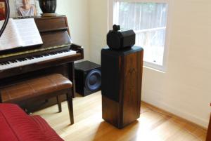
Excellent! I bought mine used, too, but it's in perfect condition. I find that the 802s aren't very efficient and need a lot of power. I bypassed the APOCs a week ago, re-blacked the grill clothes, put new feet on the cabinets, installed five-way gold binding posts and gave the cabinets fresh oil and wax (they look terrific!) but until we take down our Christmas tree they're sitting in my garage, so I haven't listened to them yet. I'll report in when I do. Happy holidays!
-
OK, I did the unsoldering and jumper last night; pretty easy. I did it on only one of the two speakers so I can play them against each other using a mono test tone, before and after. I'll use my iPhone dB meter to see if the levels change. Maybe this weekend?
-
Wow; glad it was such an easy fix! I was afraid your connector had broken, which would have been a minor pain to replace. I took apart one of my heads yesterday just for fun. It was interesting to see how the tweeter is attached by a single bolt running into the head. I also oiled my veneer and used some spray-on fabric dye to re-black the grilles. It's really looking great now. And I did the APOC mod on one speaker: I unsoldered one end of each of the six diodes, and put a drop of Goop on the loose ends to keep them from vibrating. And I ran a small wire under the PC board to bypass the relay. I also put some stick-on speaker gasket material on the underside of the edge of the crossover cover board to keep it from rattling when I reinstall it. Once I install the new binding posts I'm going to play the modified speaker against the other one on a mono signal; maybe a 1 KHz sine wave, and test them with a dB meter to see if the one without the APOC circuit is louder.
-
Yeah, the more I think about it, the more likely it seems that the problem is your head-to-body connection. An APOC problem would be more likely to cut out the entire speaker, not just the mid and/or tweeter. I am using an NAD C272 stereo amplifier, which is about 150 WPC at 8 ohms. My source / DAC / preamp is a Sonos ZP90 Zoneplayer feeding off a 1 TB RAID NAS drive. For some reason, even though the Sonos will output up to 1.7 volts IIRC, and the NAD is supposed to see at least 1 volt (again, IIRC) I can't get the system to play as loud as I would expect at full volume (not that I normally listen that way). My iPhone dB meter app is reading only 96 dB at full volume from my listening position. I have some hope that maybe the APOC bypass will allow more power to reach the drivers. Eventually I may get another C272 amp and run them each in bridged mode for 300 WPC. Today I rmeoved one of the binding posts and yes; they're pretty lame. I'm ordering some of these to replace them with these: Amazon.com: Dayton BPA-38G HD Binding Post Pair Gold: Electronics

-
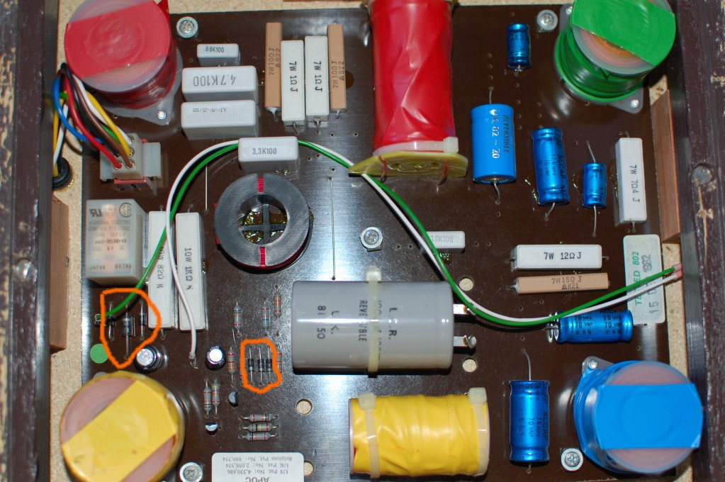
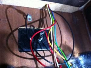
Monkey, it SEEMS, per one Jerry S and this page, plus my amateur study of the PC board and schematic, that the ticket is to unsolder one end of each of the six diodes shown in orange below (I said three, but there are really six). This depowers the APOC circuit. You can do it without even removing the PC boards from the speakers. Optionally, you can also bypass the relay, too, but that isn't necessary. You would do it only if you worried about it someday losing continuity. I have studied it, and I can see that to bypass it, you would want to solder a jumper from the center lead of the relay, to the lone corner lead, ignoring the two corners that feed the coil. I think I'll take that step, too. I can post a photo when I do it. I decided not to recap the crossovers. My research indicates that electrolytic caps dry out when subjected to too much heat, or when they physically leak. The 802 crossovers should not see much heat (unlike what they might get in an amp or a PC) and mine show no leakage. Plus, they are branded LCR and ALCAP, and my research indicates that those are both solid English brands. If they're not broken, I do not intend to fix them, and Jerry S says it makes little improvement anyway. So in sum, I'm going to unsolder the six diodes, bypass the single relay, and while I'm at it probably upgrade the binding posts, but I'm leaving the caps alone. I'm also going to leave off the crossover cover plates or put some weatherstripping around the edges to make sure they don't buzz. Any maybe put spikes on the cabinets, too. I'll also oil the cabinets and clean up all the black cloth with a damp rag.

-
I may be the only one posting in this thread, but that's OK; I think I found my answer, which is indeed, just to unsolder one end of each of the three diodes. (I also remembered that the little three-lead devices are transistors, which I used to know.) Optionally, I can also bypass the relay.
-
<crickets>
-
Update: Per this page, all I need to do is cut out all the diodes. Looking at the PC board I see six diodes lying flat and a few more of the little tripod ones. Should I remove (or clip) them all? Thanks.
-
OK, here's the schematic for my crossovers, including the APOC protection circuit (at the bottom), which is powered by my amp, and is not battery powered: http://www.bwgroup-support.com/downloads/techmanuals/bw/802-TM.pdf Photos of the crossover appear here: http://www.head-case.org/forums/do-yourself/9007-b-w-802-series-80-repair-5.html#post404176 and here: http://www.head-case.org/forums/do-yourself/9007-b-w-802-series-80-repair-3.html#post402352 and here: http://www.head-case.org/forums/do-yourself/9007-b-w-802-series-80-repair-5.html#post404221 I can see which points to connect on the PC board to bypass the relay; that's no big deal. My question is, is it true that the only other thing I should do, to bypass the APOC circuit, is remove the three diodes? Bonus question: Why would this procedure have any sonic benefits, as I keep reading? Thanks! Eric
-
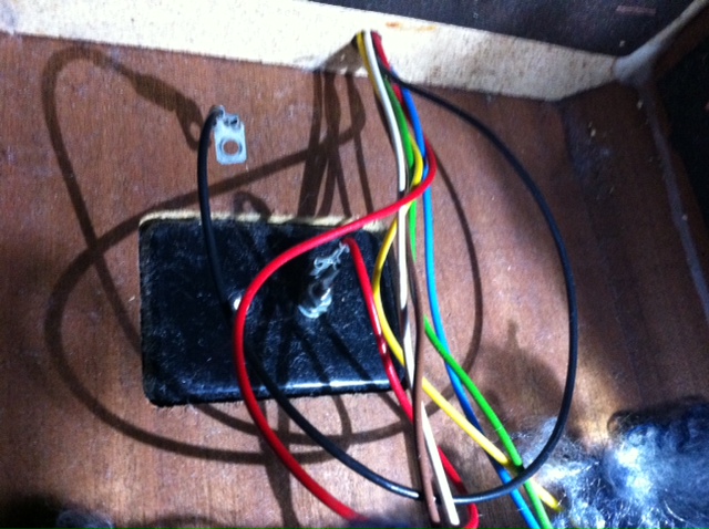
I would check both the head-to-body connecting cable and the APOC relay. Try switching heads first. If the problem moves with the head, look at the cable and plug. If it stays with the bodies, look at the socket for the connecting cable or the APOC relay. If you have to replace the cable or its socket, maybe you can find a substitute cable or socket at Parts Express. To check the APOC relay, remove the head and lay the body on its side or back and remove the bottom panel, which is held on with four Philips screws. The relay, located on the crossover board, has a plastic cover that you can squeeze and pull off. An ohmmeter will show whether you have good continuity across the two sides of the relay. I removed one of my crossovers yesterday. I think I'm going to bypass the relay just for the heck of it, although I have my doubts about any resulting audible benefits. I may also install new electrolytic capacitors using the OEM spec, and upgrade the binding posts. I may start a new thread on this project, but in short I believe that to remove the APOC circuit I should unsolder and remove the relay and the three adjacent diodes, then install a jumper across two of the remaining relay connections, i.e., the center connection and the single corner connection, leaving the other two corners (the connections that actuate the relay) open.
-
Monkey, are you going to do this? I'm thinking seriously of pulling my boards out and at least lensing them in high res, with an eye toward replacing the caps with new electrolytics. Eric
-
Thanks! That's a very generous offer and I do have a huge photo of the board. But (dammit) at the urging of some enthusiasts I put my camera into RAW mode so now, predictably, I can't open the files in Photoshop CS2, and the RAW plug-in (3.7) isn't helping. Shit. Sigh. Maybe I'll tear it open again and go back to shooting JPGs, as I've been doing quite happily for ten years now. It's super-easy to get at the crossovers, but the cabinets are really heavy to tip over and set right again safely.
-
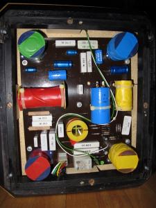
Thanks! I'm counting seven caps, and I can solder and identify a cap from a diode or resistor or transistor, but that's about the extent of my Mad electrical Skilz. Which is another way of saying I wouldn't know which caps to replace them with. Are the white rectangular units caps, too, along with the blue tubular ones? I guess I could send a high-res photo and this schematic to one of the Parts Express gurus and ask them to give me a parts list of comparable caps. I just don't want to run into the risks Monkey quoted here about screwing up the crossovers with the wrong replacements. Still gotta figure out how to bypass the APOC, too, if I so choose. I guess on the schematic posted above, I could just "short circuit" the entire protection circuit at the bottom of the page?
-
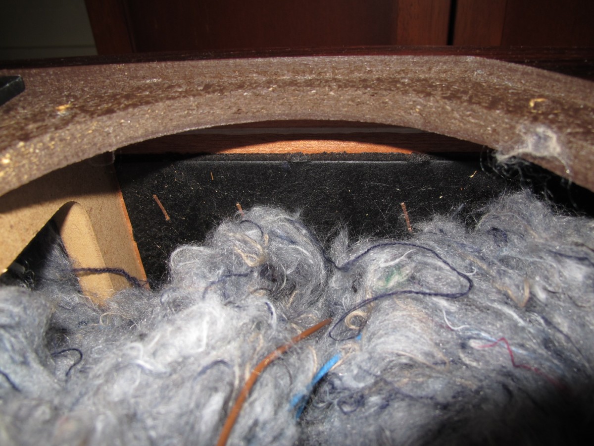
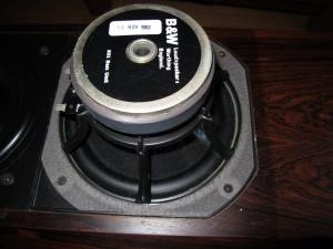
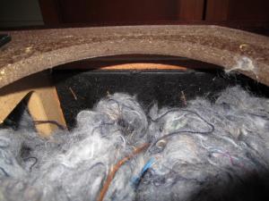
Did you know that lefties are brain-damaged from birth and live five years shorter lives than righties? At least that's what I told my sinister sister-in-law. OK, this morning I popped mine open and but for the spider spunk it's the same as the Monkey's. November 82 is the date on the bass driver I pulled. I was pleased to see a lot of internal bracing (making them almost Matrices I guess) and some heavy sound damping boards stapled to the inner walls and inner base. My crossover (APOC, no battery) looks much like the one I showed on page 3 of this thread, but without the fucked-up capacitor. The colors are a little different too. Are these electrolytics? Should I replace them? If I wanted to bypass the APOC I would cut the (three?) diodes out and remove the relay?

-
Aluminum oxide from salt air, maybe? That, or someone imported some blow using those 802s as shipping crates. I'll be curious to see the crossovers! I'm gonna pop mine open too, I think, just for fun.
-
Sorry to be all over this thread; I guess I just had a sudden burst of enthusiasm for my speakers, and thus yours, too. Anyway, I finally looked at the schematic that you posted on page one. Did you see the second page of it, with the cutaway diagram of the 802? I was pleased to see that it had a basic matrix-type bracing inside. I also noted that on it, the crossover is at the base, way below the bass drivers. Which reminded me that when I turned mine upside down, I found that there is a panel screwed onto the bottom of the speaker. I would wager that (1) that's how you access the crossovers; and (2) the crossover photo I posted above, on page three, is for the later 802s, and is wrong for ours.
-
I despise and fear spiders, and we have tons of black widows around our house. During the summer months sometimes I'll have to kill three or four per day.
-
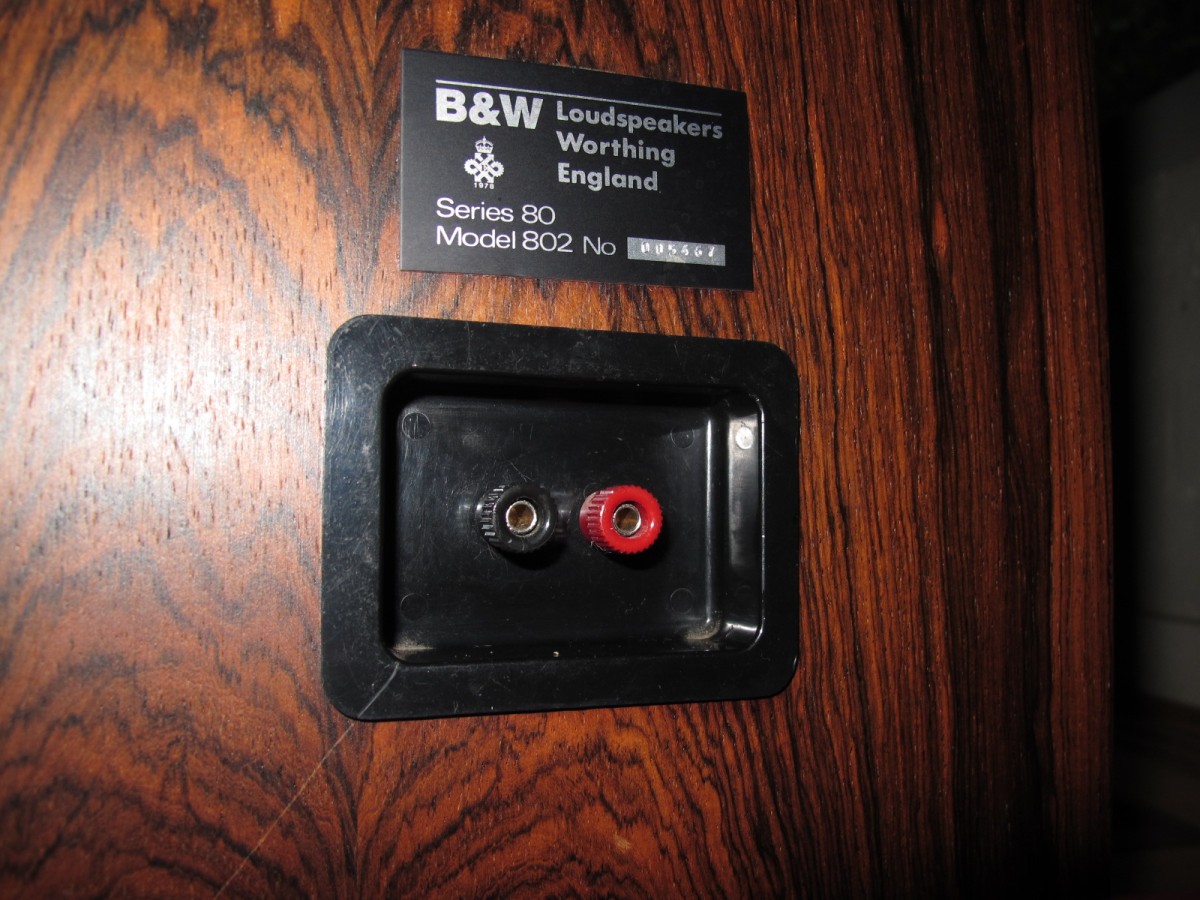
My Googling is starting to make me think that the much-reviled connectors on the old 801s are different from (and much worse than) the five-way binding posts on my 802s. I found several statements to that effect in old reviews. When I get home I'm going to take a look at mine and maybe later post some photos here. See this here, about the later series 2 801s:
-
Monkey, what kind of feet do yours have? And what are your serial numbers? (You can use Xs for the last one or two digits if you like.) I'd like to start a thread, maybe, on the different types. I need to check my serial numbers, to see if they're higher or lower than yours.
-
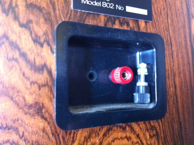
I think the OEM binding posts are set into plastic cups in the backs of the cabinets (not thick at all), so it could involve just removing the cups, then unbolting the OEM posts and bolting in new ones, plus reconnecting the internal cables to them.
-
Now I'm gonna eyeball my 802 S80 binding posts again; honestly, I don't remember them being all that bad. Nothing fancy, but adequate.
-
Partsexpress.com. See if you can remove the OEM mounting plate, unscrew the nuts holding in the old ones and screw new ones into the existing plate.
-
Then there's this: Speaker Asylum - Re: B&W 802's Series 80 - JerryS, July 31, 2006 at 09:40:06 I think this is wrong. The 802 matrix series 2 and 3 photos I've found did not refer to their being "Series 80." I think maybe the Series 80 (versions 1 and 2) came first, with no ports, then came the Matrix Series 2 and 3, which were ported.
-
Thanks, Monkey. Mine are super-clean; I think the (bookmatched) veneer is rosewood. Looks like new. They don't have the hoods over them or the posts for the hoods, but that's fine with me. The mid-bass drivers are not ported so no spiders in mine, I hope. (I recently bought some JBL 4311s for $25 on Craigslist and spent about $400 restoring them for my garage stereo; they had a dead mouse and a lot of mouse turds inside, and a Happy Meal toy.) I guess what I want to know is: Which version of the Series 80 do I have?Do they need new batteries or even have batteries?Do they have a matrix enclosure?What the heck does "Series 80" even mean? My surfing on Audiogon, eBay, here and elsewhere just gave me more questions than I had already. I've seen what appear to be my speakers, but with controls on the heads. I've seen them with ports and without. I've seen them with cloth tweeters and metal ones. I've seen them with single pairs of terminals and dual pairs. I've seen them referred to as Series 80s, IIs and IIIs. I've seen people say they have APOC or don't, and they have batteries or don't. My best guess is that the portless ones with controls were first (802 Series 80 v1?), then mine (portless without controls) (802 Series 80 v2?), then ported with soft domes and no controls (Matrix Series II?), then ported with metal domes and no controls (Matrix Series III?). But that's just my guess at this point. Phew. Too much caffeine I guess.