kh90123
Returning Member
-
Joined
-
Last visited
Everything posted by kh90123
-
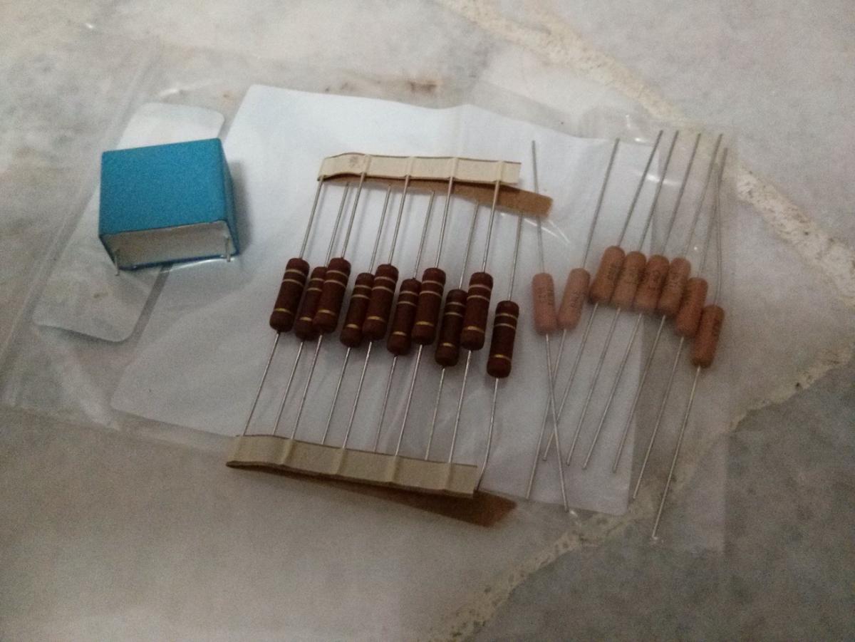
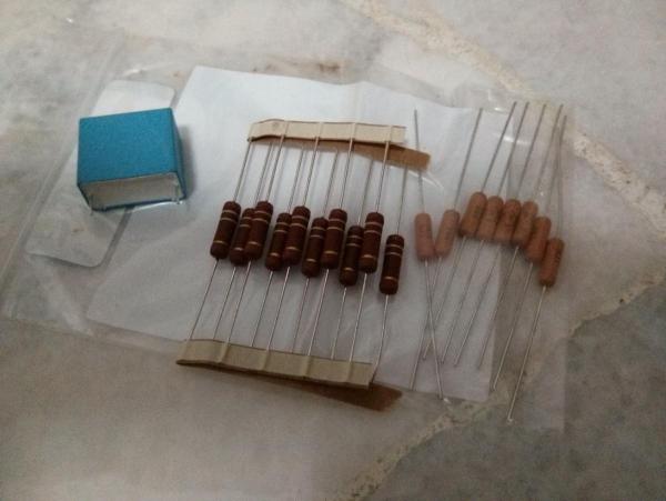
Got all my parts in today, I saw the biggest through hole 3W resistors I have ever seen. There are regen resistors much bigger out there, but those aren't as fascinating as the big round thru hole resistors. Quick question, is it possible for me to test a depletion mode MOSFET just using a DMM? I have to apply a negative bias to test it isn't it. Maybe I should get the Peak Atlas DCA 55...the DCA Pro is just a bit too expensive. I'm outta money after buying so many chips. Another one, I know how to match hfe on BJTs using the DY 294, but how do I test the LSK 389 JFETs using it?
-
Ok another thing to confirm. If I am using the ksa1156 for the PSU, I put in the 270V zener, and if I am using the 2sa1486, then I don't put in the 270V zener right? Which is more preferable? Seems like the older 2sa1486 can push more current on its collector.
-
Hi I need some advice. I know how to wire up the XLR inputs, as someone has posted a .pdf sometime ago here. I'd like to have another RCA input, but only have 2 cables from the XLR to the pot. How do I wire up the RCA input? The +ve of RCA should be connected to pin 2 of XLR right? What about the -ve, do I connect it to pin 1 (ground) of the XLR? Then if I am using the RCA input, wouldn't the quad pot be kind of floating? Please advise I think I might be wrong. Also I wonder if anyone here has made this DAC before: http://www.twistedpearaudio.com/digital/buffalose.aspx
-
Why almost all of my 680uF Nippon Chemi-con caps measured to be about 600 uF. I have been short changed 80 uF.
-
What about the fuse, is 3.15A ok for 230-240V, and is 4A ok for 115V? It's OK I can get the Motorola chips, just about 10 bucks more. I am just concerned if the performance isn't as good as the Toshiba chips. The board says EBC for the Motorola chips, while the Toshiba's datasheet says ECB, so I will have to twist the base and the collector around. I am afraid if B and C shorts out, something bad might happen. I guess if I really want it, I can prevent the twisted pins from touching using a hot glue gun. Or some epoxy. I read before that you guys mentioned that it's the output stage that will affect the sound more. Subjectively and objectively, how much worse will the amp be if I use the MPSW chips, with 2sa1486 BJT in 3rd n 4th stage, with IXYS CCS, compared to one using all Toshiba chips with IXYS CCS?
-
How come I can't use all BJTs for the onboard amp on Production Rev 0.61 ? The pin outs of the MPSW mosfet goes from EBC, while the pin out of the Toshiba BJTs goes from ECB. That means I can't use the 2sc2705, 2sc2240, 2sa970 and 2sc1815.
-
For the fuse, is 3.5A slow blow good for 240V, and for 100V/115V, is 5A slow blow OK? Or is the amperage too high? I read there were people having their 2A fuses burnt out on 240V. What about 3.15A for 240V, and 4A for 115V? If I am trying to push the current on the output stage to 8mA or 10mA, would that increase the power draw by a noticeable amount? I will also be having a 2 pole circuit breaker that is also a switch at the live and neutral. http://www.mouser.com/ProductDetail/TE-Connectivity-PB/W33-T2N1Q-5/?qs=sGAEpiMZZMvNllHT6Fj2fjyJLrUxEIJBwh69Ah0ZpOM%3d
-
I guess the lead spacing was made 3 times as wide as the one for the 0.1uF cap as it makes the tracing under the PCB easier. Sorry for sounding dumb, but I asked because there's not much reason to make the lead spacing that wide for a low voltage cap, film/ceramic.
-
What about the 1uF cap in the feedback loop of the OP 27 op amp, what rated voltage should I use? The lead spacing is 15mm. http://gilmore.chem.northwestern.edu/kgsshvproductiondual.pdf
-
Sorry typo. I meant the BJTs are getting hard to find. For those using 115V, what's the max inrush current you have seen upon power on? I am trying to get a circuit breaker switch. Also, can I use the 2sc2632 from Panasonic (http://www.classiccmp.org/rtellason/transdata/2sc2632.pdf) to replace the 2sc2705? Edit: Nevermind I bought 20 2sc2705 from eBay just now. Hopefully it's not fake. What's the difference between 2SC2240BL and 2SC2240GR, apart from the DC current gain, hfe?
-
How about MOSFETs all the way till the 4th stage, leaving the 2sc4686a in, and having the IXYS as CCS. https://docs.google.com/spreadsheet/ccc?key=0AoNVeoQi85GgdEFDQnc1aVZBdmNoc0o4WXczVGwxSVE#gid=0 Some of the EOL BJTs are getting real hard to find, and I am worried about getting fakes and having my amp blow up.
-
Kevin what do you think about using all BJTs (apart for the current source which needs the IXTP01N100D for the 500V ver) vs using all MOSFETs?
-
What are the differences between the newest onboard PCB and the next-to-newest onboard PCB? I just found that RS-components has most of the BJTs needed. Maybe I should switch my BOM to using BJTs.
-
Thanks. I have about 15 pieces 2sc4686a coming, should I keep and use 12 of those, or should I replace them with the IXTP01N100D? I guess I will have to measure them and see if I can find matching pairs. In the grand scheme of things, does it even make that obvious of a difference in sound, between using the EOL BJTs, vs the MOSFETs?
-
So I could replace Q1, Q2 which are 2sc4686a and Q11, Q12 which are 2sc2705 in this schematic, to IXTP05N100M? Is there any merit changing to the IXYS part? http://gilmore.chem.northwestern.edu/kgsshvproductiondual.pdf I haven't received my onboard PCB yet, but since it's from Lil Knight, I'd guess it should be the latest. I will have to check if the zeners are there.
-
I meant, for parts where I can put the 2sc4686, can I put that in? http://gilmore.chem.northwestern.edu/kgsshvproductiondualmot.pdf Is the 2sc4686 safe for the 500V version? I like boom, but chips are expensive...
-
Quantity available is shown as 0 for now. If it's just a 10V reference, I can always find an alternative, with the same package (PDIP-8 ) and same pin outs. The pin outs are almost like that of an op amp. REF102CP (http://www.ti.com/lit/ds/sbvs022b/sbvs022b.pdf) has a min output voltage of 9.9975V to a max of 10.0025V. Not sure how it'd compare to the LT1021-10 (http://cds.linear.com/docs/en/datasheet/1021fc.pdf) though. Also, will it make a difference in sound if I use 12x 2sc4686a vs using all IXTP01N100D?
-
Any other tips and guides, or must-do, for the 500V version, apart from those listed here on Lil Knight's blog? http://tee8tee4388.blogspot.sg/2013/07/kgsshv-amplifier.html Where can I find the LT1021-10? It's a 10V reference isn't it? What are the alternatives? What about this: http://www.mouser.sg/ProductDetail/Texas-Instruments/REF102CP/?qs=sGAEpiMZZMuBck1X%252b7j9fIs%252ba2gLkdiAHE8B2fyCBAc%3d Datasheet is here: http://www.ti.com/lit/ds/sbvs022b/sbvs022b.pdf
-
For the zener string that form the 580V pro bias, what wattage of zener should I get? I can do , +200, +200, and a +180 to get 580V can't I? Oh the PCB has 4 zeners on it (3x 150V + 1x 130V), so I guess I will have to short it if I want to have only 3 zeners. Or I could just do 4x 100V + 1x 180V.
-
Thanks for the reply. By the emitter resistors at the bottom of output stage, do you mean lowering R5 and R6 in this schematic: http://gilmore.chem.northwestern.edu/kgsshvproductiondual.pdf, which are both 180 ohm?
-
Default for onboard 450V version is 5mA, then what about the default for the 500V version? Which resistors I need to change to increase the output current? Also, where can I find LSK389/LSK170? Any alternative that's available at Mouser?
-
Instead of using 2A fuse, can I use a circuit breaker that can also function as a switch, like this: http://www.mouser.com/ProductDetail/Schurter/CFTWF030C0/?qs=sGAEpiMZZMvNllHT6Fj2fpKRYrYTMEunwydsqwE%2fDFo%3d Is 3A good? Or should I use 3.5A or 4A for 240V?
-
Hello again, Toroidy has sent me the specs and the pricing for the transformer. 100VA Triple primaries: 100V, 115V, 230V Secondary: 2x 450V/130mA, 16V-0-16V/500mA. Then there's the 150VA that goes up to 160mA for the 450V, and 700mA for the 16V rail. There's audio grade, then there's Supreme version: http://www.toroidy.pl/s783/57ad94c01a056094fc22ba3ecded9a40.jpg It's cased in such pretty stainless steel shell. Is the shell important to prevent interference? What's you guys' opinion on this? I really feel like getting the supreme stuff, but 160 dollars for the 150W transformer is not cheap too.
-
I read somewhere saying that pot with too high resistance (>100kohm) will interact with the capacitance it sees and form a low pass filter, and this will limit your bandwidth. Is this true? Or does the resistance need to be much higher than this before it becomes a concern?
-
eBay has one seller selling the Noble 25kohm quad pot, but it's linear. What about TKD pots?