

congo5
-
Posts
167 -
Joined
-
Last visited
Content Type
Profiles
Forums
Events
Posts posted by congo5
-
-
when using single bridge it seems like a good idea to solder a wire in that one hole
rather than rely on the through hole plating
-
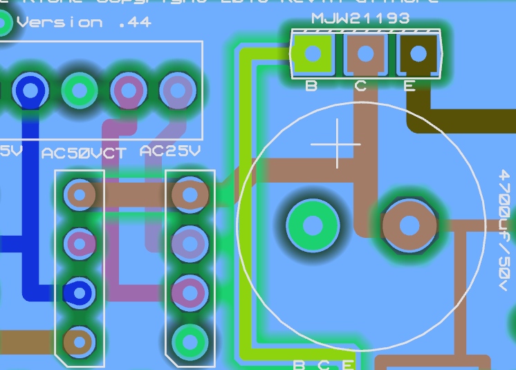
transformer input vac? blue to pink, and each to green? (center three)
brown trace connects though via on right bridge footprint?
 7 hours ago, gepardcv said:
In which case I guess I should just jumper those two points?
Lets find out where the break is first.
is it just the via? that is easy to fix.
-
just stating fact, the best I know, not to infer anything

there should be continuity between collector and pin of bridge closest to input connector
and second pin of rectifier to transformer input
a dead short like a bad cap would make the transformer unhappy, buzz and hot. I assume that isn't the case.
usually its a very simple cause, but hard enough when its in front of you to find.
I have one that is a bit noisy, like 5v of ripple at 80hz, I did the layout so you know where the problem stems from.
-
The main storage cap connects directly to bridge rectifier and collector so .1v
bad bridge or no connection to transformer?
That board is nice and clean!
What is ACV at terminal block?
the voltage is not making it through the first two inches............
-
what is voltage of collector on MJW21193?
and base?
emitter?
-
1 hour ago, gepardcv said:
What is the heatsinking story with these mini-GRLVs?
For low amperage/wattage like in pic above, copper on the board is the heatsink
for higher power you can mount it to whatever size heatsink it needs.
-
yep
imaginary one for now
-
On 8/9/2016 at 4:13 PM, kevin gilmore said:
http://gilmore.chem.northwestern.edu/kgsshvcarbonpsleft.jpg
http://gilmore.chem.northwestern.edu/kgsshvcarbonpsright.jpg
older power supply schematic without the on/off switch
http://gilmore.chem.northwestern.edu/goldenreferencehvsic.pdf
you can use that schematic
and figure out the extra three partsnow I see its been added,BOM is harder, write down the silk screen and look it up or wait for Kerry.
Haven't seen any build this but Him
-
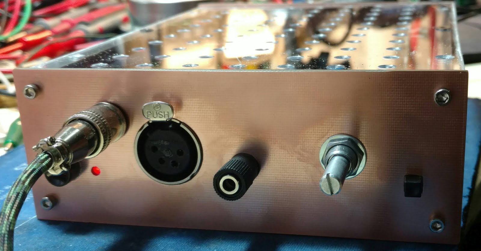
That looks great, very much like the looks, the clean rounded face and color, the lettering and ventilation
-
I used the first one I found and it was close enough to trace out the board and label it.
Do not see a link here for Diffinput3.pdf
I do have a draft copy with sim graphs on it.
-
Well its the one I have......
the CCS LED/10k resistors go to ground instead of each other
and Servo eats DC at the output
That's all I noticed.
-
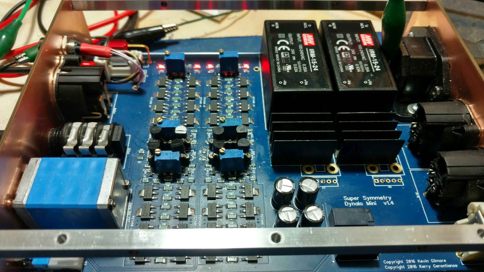
Kevin's SMD layout, adapted a bit for my methods
Servo's work

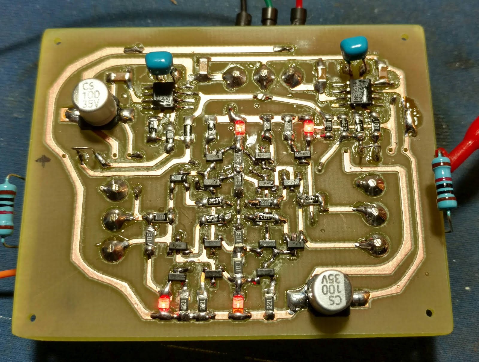
and a plug in buffer with 1W MPSW transistors (for Turbo)

It seems that I like buffers............
-
Here are the original ones from Kerry, don't think he will mind..
https://drive.google.com/open?id=0BwUlR99qUHFqY1YxRjFfcnA1X1k
1 hour ago, johnwmclean said:nice work, impressive soldering.
Well that was after several hours of trial and error, next time I should just order the prebuilt ones.
Kerry thanks for the beautiful layout, files, schematics and advice.
This was quite different from the norm, a nice adventure.
-
 1
1
-
-
here is a dxf file that is modified, https://drive.google.com/open?id=0BwUlR99qUHFqQnVZcGkzMjBva3c
I enlarged it .250" to allow for 1/4" square stock to use as a frame
and made other minor changes, its not perfect yet but getting close.
RCA hole size increased to fit the lip around them.
the IEC corners have been rounded more but haven't tested that
also want a round button instead of the square one
test pieces out of PCB

and yes I cheated on the trimpots
and I find these very hard to solder:
-
9
-
-
8 hours ago, johnwmclean said:
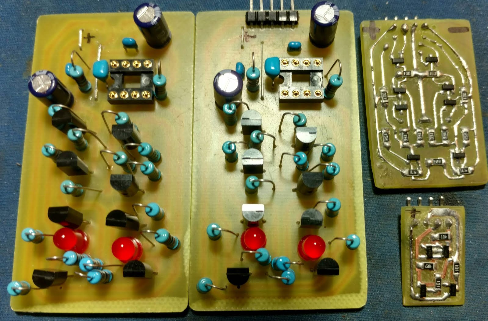
servos need to be removed
or put the 0 ohms resistors on after, they connect pin 6 to the center of the 49.9k's
I took them off for biasing
-
3
-
-
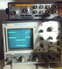
Messing with this tonight.
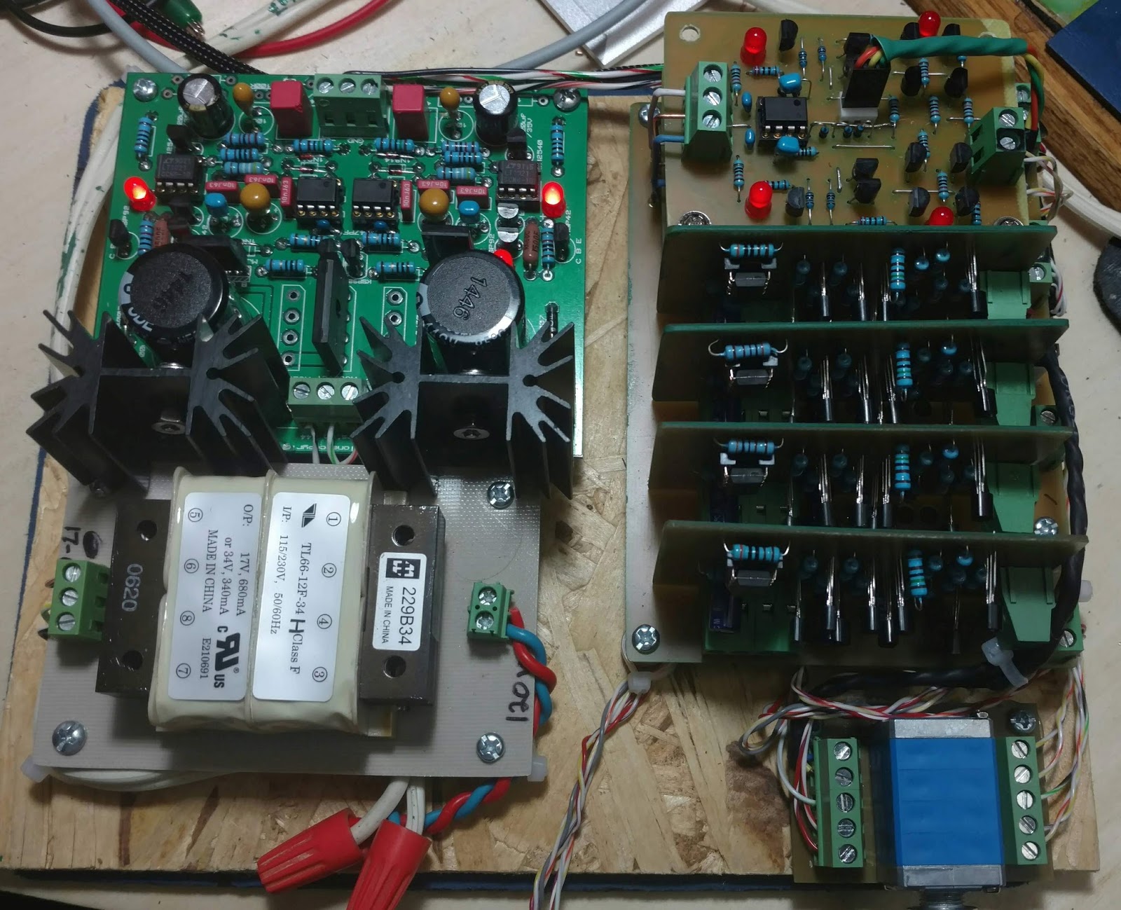
Its playing into balanced ortho's. the gain is stock at 2 and its just enough, not real loud but sounds just great!
yes this is meant for Pre duty, this is one way I test them.
that 12va transformer is too small, but was just sitting here. 20-25va would be better.
GRLV is set for +-18V heat sinks are 35C, with 4V of regulation
the buffer's are setup for 18v & that way I can use the cheaper servo's
room is 20C, buffer output transistors are 40-46C, transformer 42C
-
7
-
-
37 minutes ago, cspirou said:
To power 2 ubal/bal boards and 4 diamond buffer, is one GRLV enough?
checked my through hole one, (full size) its just under 200ma total with two inputs and four buffers
one GRLV is enough for several of these
-
1
-
-
yes looking too, mostly use harbor freight visor but want better
seems that you have to spend hundreds to get past the junk.
on a side note:
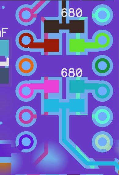
if you solder the 680R parallel with the lettering ....It just does not work!
gotta love hot air
-
8 minutes ago, HemiSam said:
Might have to spoil myself with one of those.
Yes, want! don't have small pencil
on Flux: its a big deal, what he has is way better, the kester boils off quick and leave's more residue but works
I got the positive regulator on the first try, but took three times on the negative Had too much solder under and some side pins would not make contact.
flux dries> solder won't stick> start over
going slow and careful as I only have one board, that took half a day ;-)
Really want the microscope + camera.
-
2
-
-
under video description click "show more"
✖ TOOLS USED:
● Flux: http://bit.ly/2cYIx7t
● Solder paste: http://bit.ly/2epK1JE
● Soldering Iron: http://amzn.to/2cKkMyO
● Preferred tip: http://amzn.to/2d5MgPn
● Micro Soldering Pencil: http://amzn.to/2d5MWUP
● Micro soldering tip: http://amzn.to/2eYrF4a
● Hot Air station: http://amzn.to/2d5M7Lw
● Hot Air EXPENSIVE: http://amzn.to/2cYI6tY
● Tweezers: http://amzn.to/2d5NBpi
● Multimeter: http://amzn.to/2cYJY5T
● Multimeter Probes: http://amzn.to/2cKkvMh
● Fume Extractor: http://amzn.to/2d5MGoD
● Microscope: http://amzn.to/2iLrE16
● Microscope LED light: http://amzn.to/2d5Mh5T
● Solder: http://amzn.to/2cKkxUp
● Crest CP500HT Ultrasonic cleaner: http://bit.ly/2iv3aci
● Branson EC cleaning fluid: http://amzn.to/2cKlBrp
● Jumper wire THIN: http://amzn.to/2eqF5T7
● Jumper wire THICK: http://amzn.to/2eAJ5AU
● Nitrile gloves: http://amzn.to/2iUfumS
Bench PSU: Agilent 6542I'm using Kester.
turn down the blow.
hold with twezers
mask off blow zone with aluminum foil?
-
2
-
-
Yep, real world actual work not 5 takes and edited
Thanks
-
1
-
-
Totally my fault, not the circuit!
I was running SOT-23 devices like they were TO220
will adjust for sane values (75mw) and test soon
-
yes 3.3nf
Safety Ceramic Disc Capacitors I think he may be doing it different ways to show possibility's, both are valid, notice a different thermistor is used
there are other designs shown in the other amp guides, different ways to do the same thing, different ground loop breakers.. and so on.
notice how he does the secondary connections to bridges, completely different
one center taped, one normal but really its the same result, isn't it?
-
20 minutes ago, Skooby said:
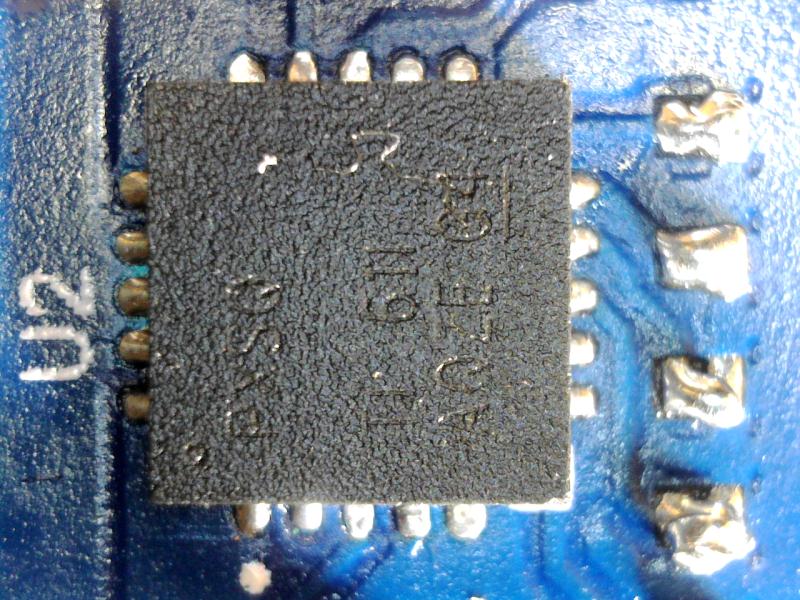
solder the TI 7A4700
watch Louis Rossmann - YouTube
I used a candle warmer to preheat the area.
clean the pads
liquid flux
tin the pads
clean
reflux
use hot air station
solder with silver content helps with gold plating.
-
2
-
Stax SR-40
in Headphones
Posted
yes
be careful with the volume