ervstil
-
Posts
11 -
Joined
-
Last visited
Recent Profile Visitors
739 profile views

ervstil's Achievements
Member (2/6)
0
Reputation
-
Yes there is a boards for it, but I already have a populated boards from the first group buy and want to make use of it. I already plan to mount the CCS of board so it would be easy to make a add on board with Kevins new css and connect it to B+ and pin 9. I would then remove the resistors not needed. I will get the amp running unmodified but I will mount the 10m90s so it i have room for the add on board if I want to. I also wondering abut the procedure and measurements for adjusting the cascode. B.r Christian
-
Now I have a good plan for the ground and case layout. Unlike my other projects, this amp will get at really nice case, hopefully I will get the time to finish it this weekend, pictures will follow. I have a spare EI transformer and the next projects is growing in my head, JimL:s SRX. When going through his excellent documentation (thanks JimL) i cant stop thinking that his cascode CCS make sense for the KGST as well and I will probably make room in my case for a future cascode CCS based on Kevins new circuit on an add on board. Is this a good or bad idea? B.R Christian
-
Thanks JoaMat. Yes, it looks very similar. The difference is that i my scheme the amp grounds and the chassis star ground are connected at the same terminal at the PS. Question is which GND to use on the AMP boards. I'm thinking the GND at the HV and output terminals, but i am not sure.
-
Thank for you replies! I have learned two things. 1. The tubes will have similar temperature. 2. It doesn't matter. Still wondering about the grounding scheme though, with two grounds on the PS ant two in the AMP board it is easy to create ground loops. I´m thinking about using the output terminal on the PS as a star ground for signal and and power, connecting only one ground lead to the AMP board. That star ground will be connected to chassis and earth. XLR Pin 1 will be connected to chassis. Any thoughts. B.R Christian
-
The tubes are cooled by IR radiation only, the glass envelop absorbs 25 to 75% of this radiation (based on other estimates om the net) so i´m guessing 50%, including re radiation. I think it is reasonable to estimate 50% radiation and 50% convection for the tubes. Only the convection are affected by the horizontal mounting. I took some help from a engineering friend who did a quick and dirty simulation at work. Based om the the above assumption and max power plus filament we arrived at a envelop temperature at approx 210 Celsius for both tubes the upper tube are cooled by hotter air but it has higher velocity from the convection from the lower tube. It all ads up being the same temperature for both tubes. So based on a 10 min simulation done by two idiots without any knowledge, there is no problems....
-
Well, the data sheet says operating position: any, so i do not think that is any problem. The absolute heat will not be a problem either, the case is extremely well ventilated. My worries are that the two devises in a ltp operates at different temperatures. I am used to mounting ss devices in an ltp rather close on the same heatsink to keep their thermal drifting similar. Do tubes have the same issues as ss? Regarding position of the board. If I rotate the board it will be difficult to mount the ccs off board keeping the wire length short.
-
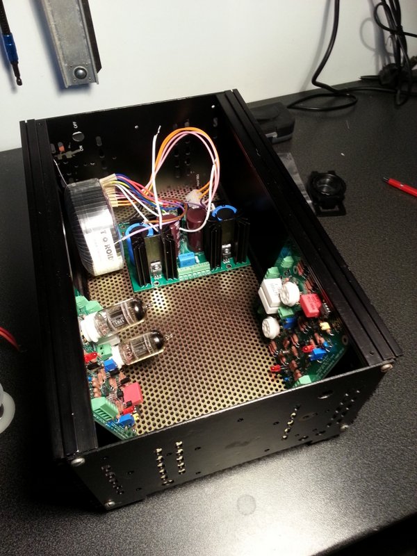
Hi! Finally, i got my boards populated, preliminary tests of the PSU looks good with 361v and 367v unloaded. Before i can test the AMP boards i must get some work done on the case. The reason is that i will have the CCS mounted off board. The main reason is the a got a nice surplus case with excellent ventilation, the only problem is that its slightly narrow and the amp boards does not fit side by side. The case it rather high and the sides consists of heat sinks, so one solution is to mount the amp boards vertical on the side wall and the ccs off board on the side wall heatsink. The added bonus is improved cooling with the heat dissipated directly outside the case. I have some concerns though, In the most natural position the tubes will be mounted horizontally with one tube over the other. They might see quite different thermal conditions with the top tube right in the way of the bottom tubes convection. Will that be of any concern? Another unrelated question: Each psu board has two ground terminals to a common ground for both power and signal. I have some troubles finding a grounding scheme that does not introduce a ground loop. Is there a 'standard ' grounding scheme? How do you do it? Best Regards Christian

-
Thanks spritzer for the fast reply. Will the 400v version give me more usable voltage swing? Will it make any real world difference for inefficient headphones? BR Christian
-
Hi! I can see that most of you already come a long way with your builds. This turned out to be a slow starting project for me as I´m have really limited time and founds. I have built many amps of all varieties but never played around with tubes. Driving electrostatic is the first application where tubes makes at least some sense to me. One of the main features is that they glows in the dark, so I figure why hide them? I start to think that i will configure it as a classic tube amplifier with exposed tubes mounted on a top plate. I will also mount the ccs transistors on an external heatsink. An added bonus with this configuration is that I can build a cheap case mostly from exiting material. - Given that most of the heat will radiate outside the case would it be safe to use build the 400v version? - I'm working on a pair of DIY headphones and right now they are really inefficient compared to my stax 202:s. Will the 400v v version give me more headroom for tough to drive headphones? Is there any other advantages at all with the higher voltage version? - I there any issues of mounting the CCS and tubes off-board (added capacitance by cabling, hum from longer loops etc) except the obvious safety and practicality issues? - I imagine that if the tubes are exposed to the free air their running temperature will fluctuate more within the LTP pair. It can be an issue with fets, it is the same with tubes or will the differences be swamped by the higher temperature? Best regards Christian
-
Thanks spritzer! I was under impression that the was up to date bom:s for 450v and 500v versions. I found one on an external site "D.I:Y Power", maybe i would have look up the validity of the substitute pars in that bom. Is there a big sonic difference between different versions? I guess with the 400 version i can reuse the Power supply if (when) I get the urge to build myself an KGST. Best Regards Christian
-
Hi! I'm new to the forum, but not new to building amplifiers. A couple months ago I borrowed a set of SR-5 with adapter, hooked it up to my Pass F5 and ...wow. After that my dynamics felt so dull and distant. I immediately realized that i need to get some good electrostatics and build my self good amp. Since then i have been lurking around this forum, learning as much as possible about the different designs, especially Kevins. By the way, thank you all for sharing! Before i start to etching boards and winding transformers, i have a couple of questions. - I have never built a tube amp, mostly because in normal amps solid state make more sense, but in the world of high voltage and high impedance the transformer disappears and it suddenly tubes make all the sense in the world. I'm very tempted to try the tube designs but: the BHSE design is not available, the standard Blue Hawaii is very hard to source parts for. The KGST looks very tempting, but I suspect that I will get more proven design and higher performance for by labor and bucks with the KGSSHV? So, can KGST compete with KGSSHV? - I actually started to lay out a point to point schema for the KGSSHV, but the part count and the high voltage makes it rather bulky and somewhat dangerous... Is there someone that can share a reasonable stable, compact and up to date layout of amp and PS of KGSSHV and KGST for etching? It would save a ton of time and money of trail and error. - Regarding voltages for the KGSSHV, what do you recommend for performance and parts availability? Thanks again // Christian Stille