


Helium
-
Posts
129 -
Joined
-
Last visited
Content Type
Profiles
Forums
Events
Posts posted by Helium
-
-
Edit: one idea, is maybe log taper of the pot was too steep. Need to try another one.
-
On 4/16/2025 at 2:42 PM, jamesmking said:
As far as I know most of Kevin's valve and value/transistor hybrids aim for a gain of 1000x - thats what the mostly modern T2 has and I think the blue BJT blue Hawaii. The only exception I have experienced is the (standard) EL34 Megatron which has lower gain.
It's definitely quieter. Reasonable loudness is reached at 15-16 o'clock.
Pot is 10k series type, B+/B- is 400vdc, but those don't affect volume.
The only change I made is I used TTA004B,Q and TTC004B,Q instead of KSC2690AYS and KSA1220AYS. I doubt that it could be the reason as they are direct replacements.
It would be nice to find a solution.
-
Did anyone experience that BH BJT is quieter than other Stax amps? Like 15 o'clock vs 12-13 o'clock on T2. Is there any way to increase gain?
-
On 6/14/2023 at 2:30 PM, audiostar said:
320Vac @ 0.18A -> 400Vdc
365Vac @ 0.18A -> -460VdcCould someone explain the rule for choosing VAC secondaries of HV transformer?
Rule of 0.707 (400VDC as target + ~10V of voltage drop = 290VAC÷0.707) doesn't apply here? Should we add 30-50VAC (or how many?) for voltage drop and regulation? Thx.
-
Thanks, spritzer
-
I've searched but couldn't find answer. Can KGST work with 450v power supply?
-
On 5/3/2024 at 9:57 AM, MLA said:
Working on a BH at the moment, and given what you found regarding Cob for 2690; do you think it would be worthwhile to use TTC004b instead, or is the difference too small? I guess you may have checked it but discarded it as an option?
Seems that KSA1220AYS may also be replaced with TTA004B,Q? The latter also seems better.
-
Yep, I myself had to scroll this thread again as Im in the process of building one.
I think the mod is referred to this post:
But I dont see what resistors were XXohm value in the original design and became 33kohm in the updated design as Im building the latest rev of PS PCB (speaking of original DIY T2).
-
On 1/8/2011 at 1:50 AM, Craig Sawyers said:
(1) The power supply mod developed by Kevin and Inu to make it stable
Can anyone please point this mod for me?
I can't find it reflected in the (latest?) schematic or PS PCB.
R14, R29, R41 and R53 resistors are all 2.2k, or am I looking at wrong locations?
-
8 hours ago, demonkuro said:
Thank you for your concern, before connecting the PSU to AMP, I let it work independently for several hours, all the output voltages are right, the drift is very small, and it looks very stable. So I confidently linked it to AMP, but nothing good happened... Just like the carbon I made 8 years ago, the PSU also exploded, and that time I replaced the damaged part and it worked fine. Thanks to your advice, I will go find an insulation tester to test each power supply. I should be more cautious.The PSU was tested today and luckily all worked fine except for -500V and +500V.Waiting for new parts and replace the wire with a higher withstand voltage rating.
Did you trim snap-in capacitors leads underneath PCB? Seems that PCB is quite low and may be touching bottom cover. Once I made same stupid mistake. Without load PSU was OK, but when I connected amp section, it exploded quite spectacularly.
-
On 5/14/2023 at 5:01 AM, Satyrnine said:
Welp after all that work trying to stuff a quad cfa into a 3U, I think I'm going to add a ubaltobaltubeschem2 and grhv100, and go split chassis. Anyone have any ubaltobaltube or grhv100 boards?
Any specific reason why you would put tube unbal-bal converter in front of CFA? Just to make it as complicated as possible? There will be ~100 more parts in signal path, hardly they will make amplifier sound better.
-
 1
1
-
-
I would use different layout.
Move transformers and grlvs to the front. Move cfa to the rear. Keep DC protection board where it is at the front. Use extension shaft to mount volume pot at the rear close to inputs.
Side notes: move ac inlet to the left or right, it doesn't have to be on the center, it gives nothing. Stack the upper cfa higher so that transistors are distributed more evenly over heatsinks area. Move inputs closer to center (and to the pot) and move speaker terminals to outer edge of the chassis. Cause your speakers will be placed to the left and right and maybe quite far away from the amp.
Consider stacking transformers on top of each other, you have 120mm clearance if you don't use steel chassis.
That way you will have space to mount grlvs horizontally.
After all I don't think that amp with bjt output transistors is good to drive speakers. I would consider omitting speaker terminals completely.
-
1
-
-
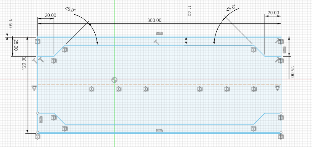
1 hour ago, Satyrnine said:
You don't happen to have dimensions of the bracket do you?
Here they are.
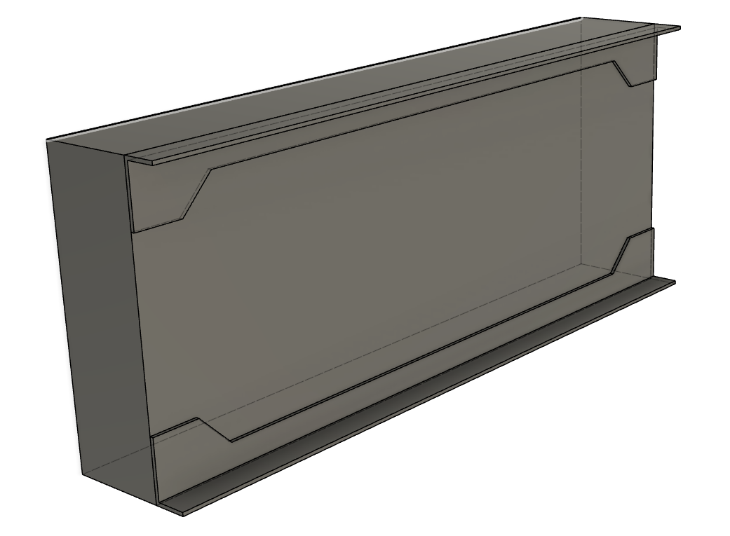
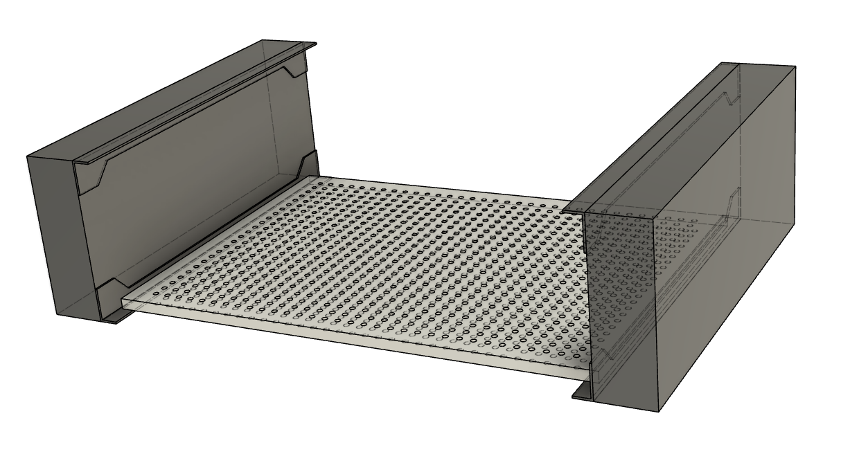
Consider 2-storey layout, where CFA boards are mounted on top with each other and to L-brackets on heatsinks.
This is what I have in mind for my CFA3 project.

-
1
-
-
This is how 3U heatsink looks like with brackets installed.

-
1 hour ago, Satyrnine said:
I haven’t, thanks for the heads up, definitely the reason I posted here before finalizing/ordering. Thank You! That said, Dukei is the one who suggested it, sounding like it was possible. I’ll touch base with him on those concerns and either redesign or report back with a possible solution.
As far as the steel floor chassis add on, this is good to know too. The trafo covers i ordered through antek are nice and beefy and support/clamp to the bottom plate around the edge of the cover as well as via the thicker/wider center support which maybe would prevent/reduce any rigidity related issues vs bare toroid? Def open to the add on support, but prefer not to if possible, if only for aesthetics. Since I’ll be assembling myself I don’t have to worry about shipping with trafos installed at least.
Well, I myself don't like mounting trafos on aluminum plate. Dissipante comes with 3mm anodized top and bottom plates, mounted with 4 small screws m3. For me this structure is not very good to sustain weight of trafos.
Moreover, if you use steel chassis to mount everything inside, you can do without any holes in bottom plate (except those for feet).
-
4 hours ago, Satyrnine said:
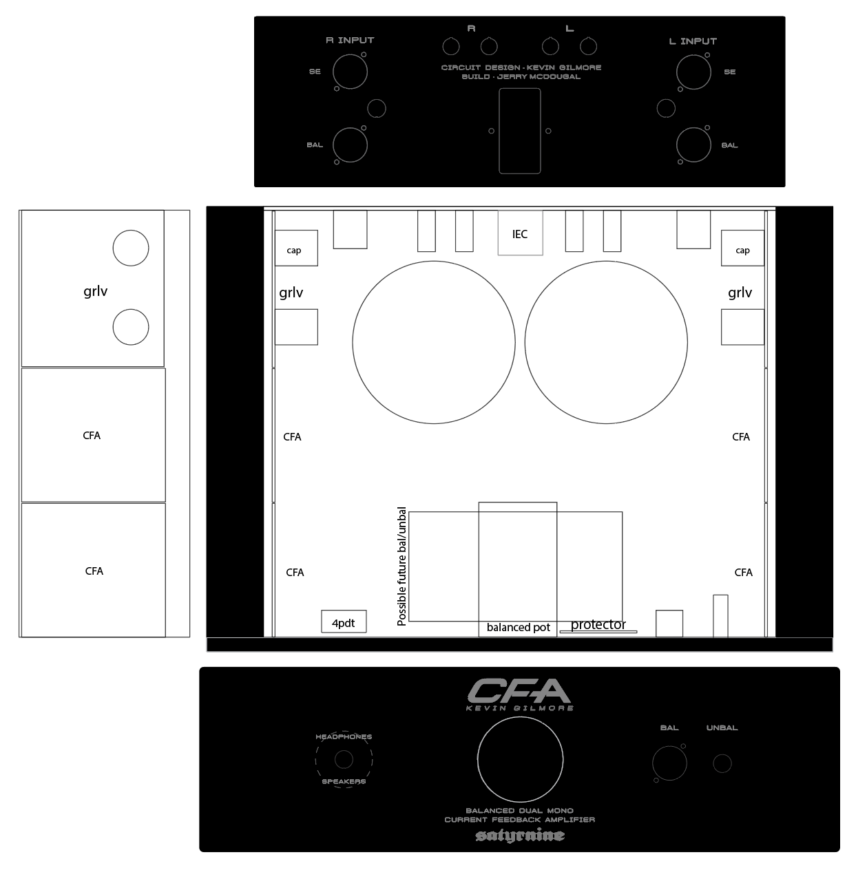
Almost ready to start building my CFA2/3!
- Dual Mono, 2x GRLV, 4x CFA2 boards, and maybe a bal/unbal down the road. I plan to use this with my LCD-2's (orig), and my desk monitors via added speaker outs. I have all the components on hand but the chassis so far.
- Details: Dissipante 3U chassis. Mounting boards directly to heatsink.
- 2x Antek 100VA 30V trafos with steel covers
- MUR820 Ultra Fast diodes on daughterboards vs standard GBU4 package rectifiers for GRLV boards
- Goldpoint quad/balanced stepped attenuator
- KG Headphone Protector Board (just had a set made at Oshpark)
- Options for Bal and SE in
- Bal and Unbal outs (unbal out only works with se ins in CFA2 mode obv)
- Dale RN60 resistors throughout, Used Pars's BOM
Here's what I have drawn up so far for Front/Rear panels I'm having made at Modushop, as well as internal layout plan thus far. Getting panels engraved/machined, with the "CFA" cut deeply at a bevel. Large circle where vol knob is is just a placeholder for the largest possible size knob. Dotted line around headphone/speaker switch is a rear recess since front panel is 10mm thick.
Many Thanks to the infamous Dukei/Miroslav and Pars for guidance, as well as arteom from diyaudio for generously supplying boards, and of course the man himself for this awesome design.
I used modushop dissipante quite a few times. I doubt that you will be able to mount boards on side heatsinks this way. Have you accounted for steel support brackets that take up significant area of the heatsinks, and use of steel chassis on the floor? Since you are mounting transformers on the floor it's good practice to use steel chassis (sold separately) to get extra rigidity.
-
 1
1
-
Ok, no one is issuing orders (except that taking a breath can be regarded such). Why such tone?
-
Not sure if DIY forum where people come together to share interests is an appropriate place for such things. There is too much hostility and hate in life nowadays, don't bring it in here.
-
10 hours ago, johnwmclean said:
One channel of my latest build has little to no drift at all (no servos installed), which is odd behaviour from my experience.
After 45 minutes warmup offset and balance can be trimmed to under 1VDC.
From a cold start everything is now under 1 volt and stays that way. I’m curious as to the reason, do I need fix or leave as is?Wait a minute, are you telling that no drift is something wrong?
From my experience there is some drift (0.5~1VDC without servo, and ~200mVDC with optoservo installed, both balance and offset), and I wish it wasn't there.
-
If not sold, are you going to transfer most components to split boards?
Out of curiosity, are split boards so much better than wider boards to justify hard work of desoldering and soldering a lot of parts?
-
On 1/26/2022 at 10:33 PM, Rinat said:
Are they from the same batch?
Yes, same batch.
Seems that Hakko 808 isn't ESD safe. Lesson learnt.
-
Did anyone experience how vulnerable DN2540N5 are?
They are damaged so easily that I had to scratch my head.
E.g. desolder it from a donor known good GRHV, actually new (don't ask why, I had to get spares) and it's detected OK in circuit as N-Ch depletion mosfet.
I desolder it, test it and BAM it's no longer depletion mosfet, it turns into kind of Voltage regulator. And doesn't work of course. I spoiled 4 pcs already, despite the fact that I know how to desolder and handle components. And only one out of 5 was OK after desoldering.
-
 2
2
-
-
17 minutes ago, Beefy said:
Would the phase of the transformer secondary windings be an issue here? There doesn't seem to be anything indicating the start of a winding, both wires of each winding are the same color.
I know that getting the phase wrong can cause issues when tying windings together to create your own centre tap.
I checked phase of all windings prior to connecting. Yes, they are not marked, I marked them by myself. And connected both HVs in phase.
4 minutes ago, jamesmking said:can I ask a possibly dumb question, I see the grlv with fully populated + and - sections,
the board attached to the side wall seems to be a grhv but it only looks like a single rail grhv which would mean its either +400V or -400V i does not look like a dual output board to me.....

Yes, it's single -400 board. The other one (+400) is dismounted ATM and waiting for a part for replacement.
-
9 minutes ago, jamesmking said:
since the grlv and grhv have separate transformer windings they are floating with respect to each other.
with only one amp being grounded through the grhv that amp board is tied to that psu but would have no idea what the LV voltage is since the LV floating with respect to the hv psu and nto referenced to it. The other amp board being grounded through the LV only would have no idea what the hv voltage is in relation to the lv voltage....
you would see this by measuring the voltages on one amp board with the multimeter neg on that amps ground and then measure the voltages on the that amp board with the multimeter neg on that amp boards ground.
Another way to think of it is electricity flows in a circle, for the amp connected to the hv board the electricity comes out of the hv board goes into the amp board and returns to the hv board through the ground wire, The Lv electricity enters the amp board BUT has no return path direct or indirect to the LV board... and visa versa for the amp board connected to the lv ground only....
This is why I check the psu voltages of a fully built amp at the amp board using the amp boards ground and not at the psu using the psu ground....
Wait a minute please. I see what you mean.
Is the transfotmer up to the task? That's most unfortunate if it's not. Is Star ground of everything a cure?
Technical Assistance/Advice Thread
in Do It Yourself
Posted · Edited by Helium
Is electrolytic capacitors reforming needed? What is common attitude to this procedure?
I've got quite a few pcbs that I completed 8-10 years ago. Most projects are from amb and KG. I soldered PCBs, washed them and put aside on the shelf. But life is life, time has passed and finally I thought that this year it's a good time to complete them.
Pcbs were never switched on. Caps I used are all good if not the best brands: Panasonic, rubycon, nichicon. Never frozen, never heated.
However I'm confused how short the shelf life is according to manufacturers specs: 2 years, maybe 3. I remember receiving caps from mouser that are almost 2 years old, I'm curious what they do after 2 years, dispose them?
Anyway, do I need to do anything about caps? Do they really degrade, or is it just a BS from manufacturers to stay on safe side? Maybe 8-10 years are nothing to worry about? I really would avoid desoldering and replacing everything if possible.