Helium
-
Posts
130 -
Joined
-
Last visited
-
Days Won
1
Content Type
Profiles
Forums
Events
Everything posted by Helium
-
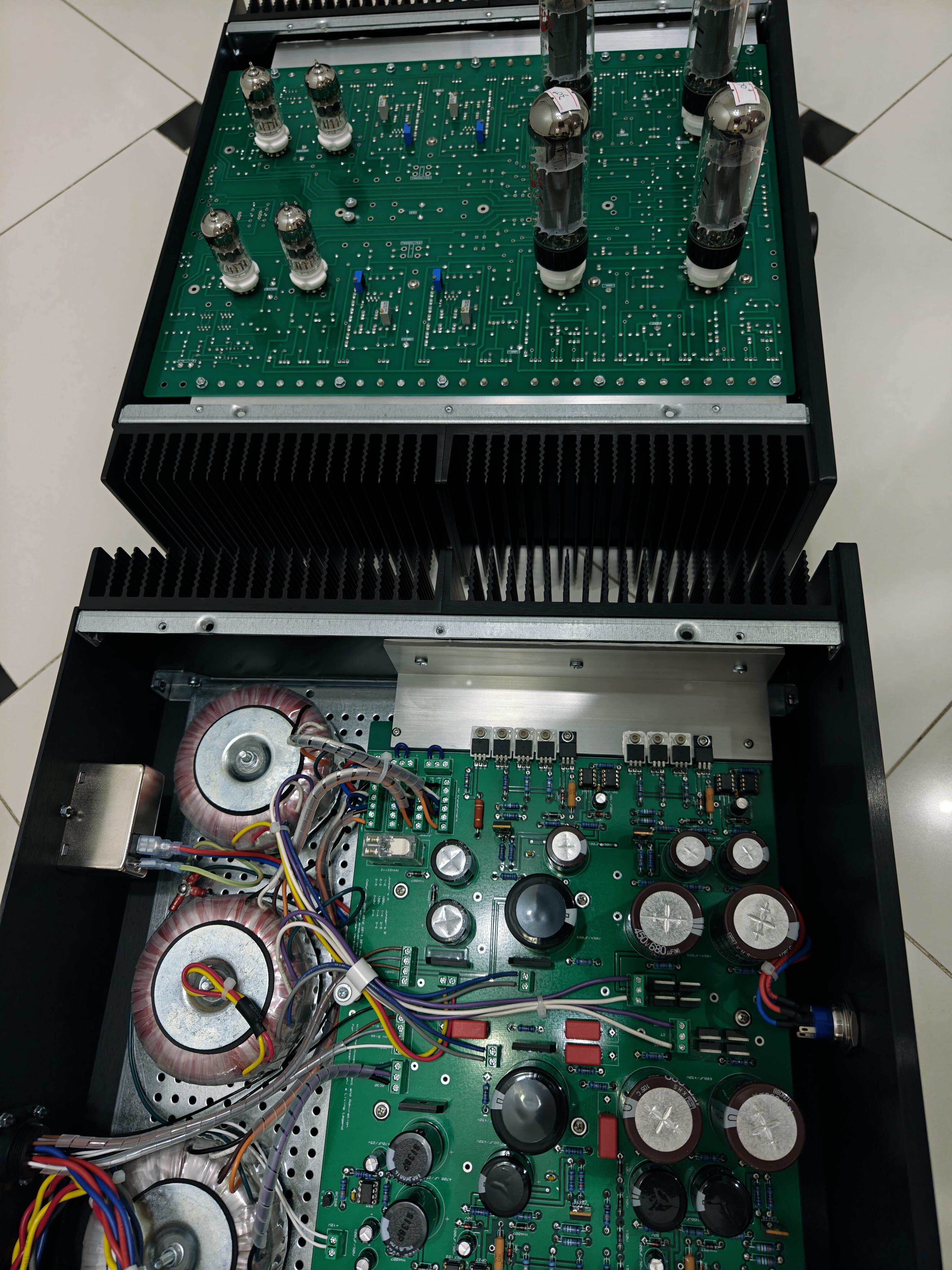
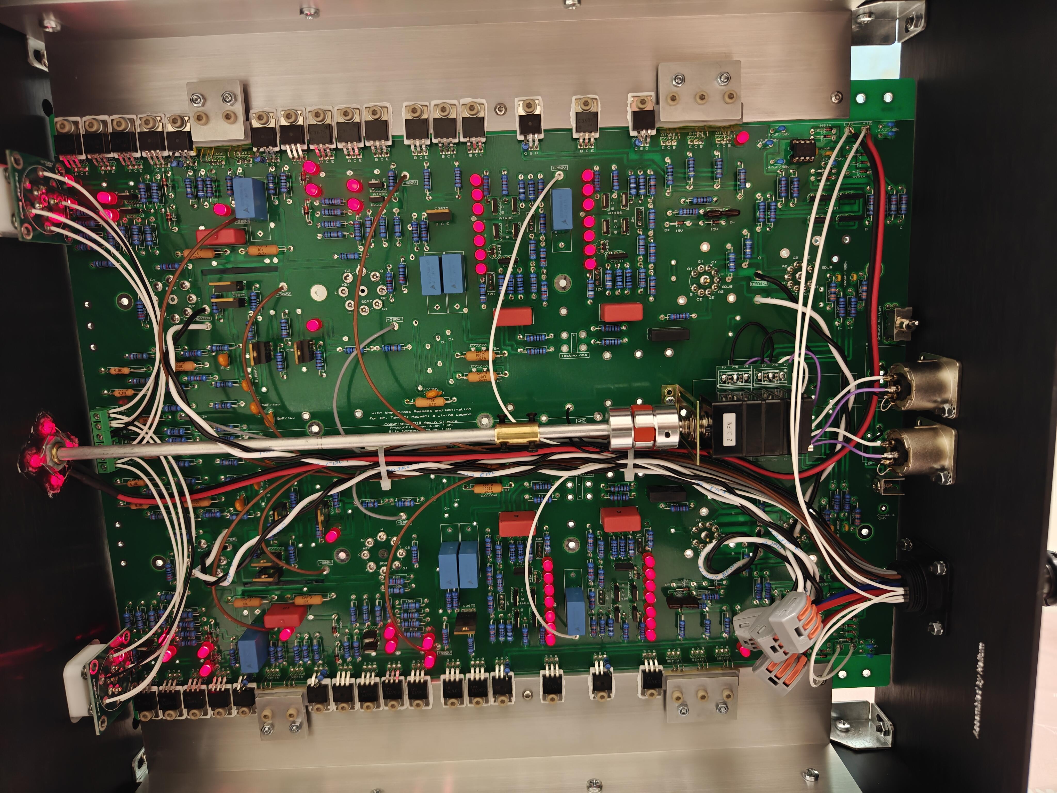
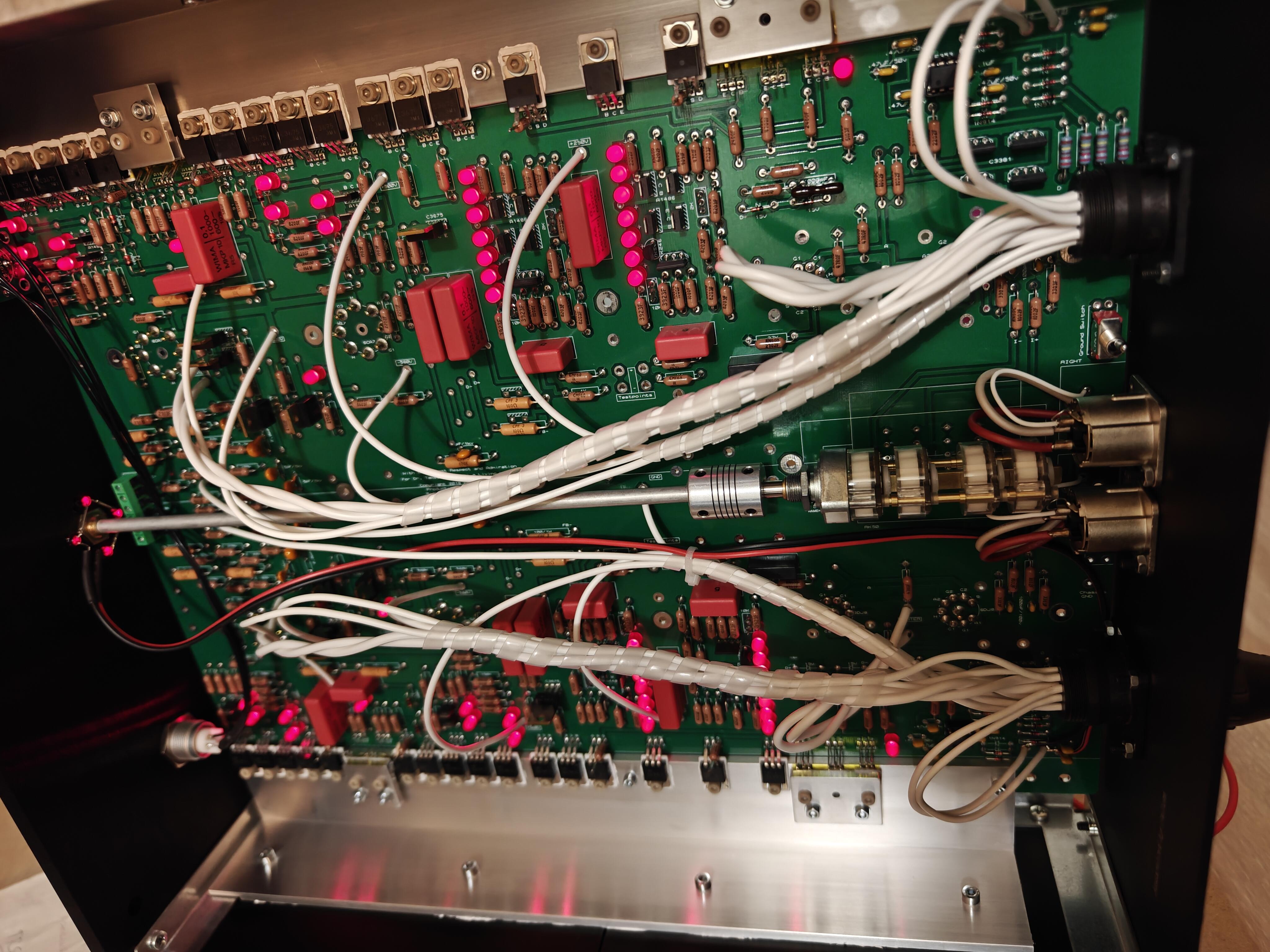
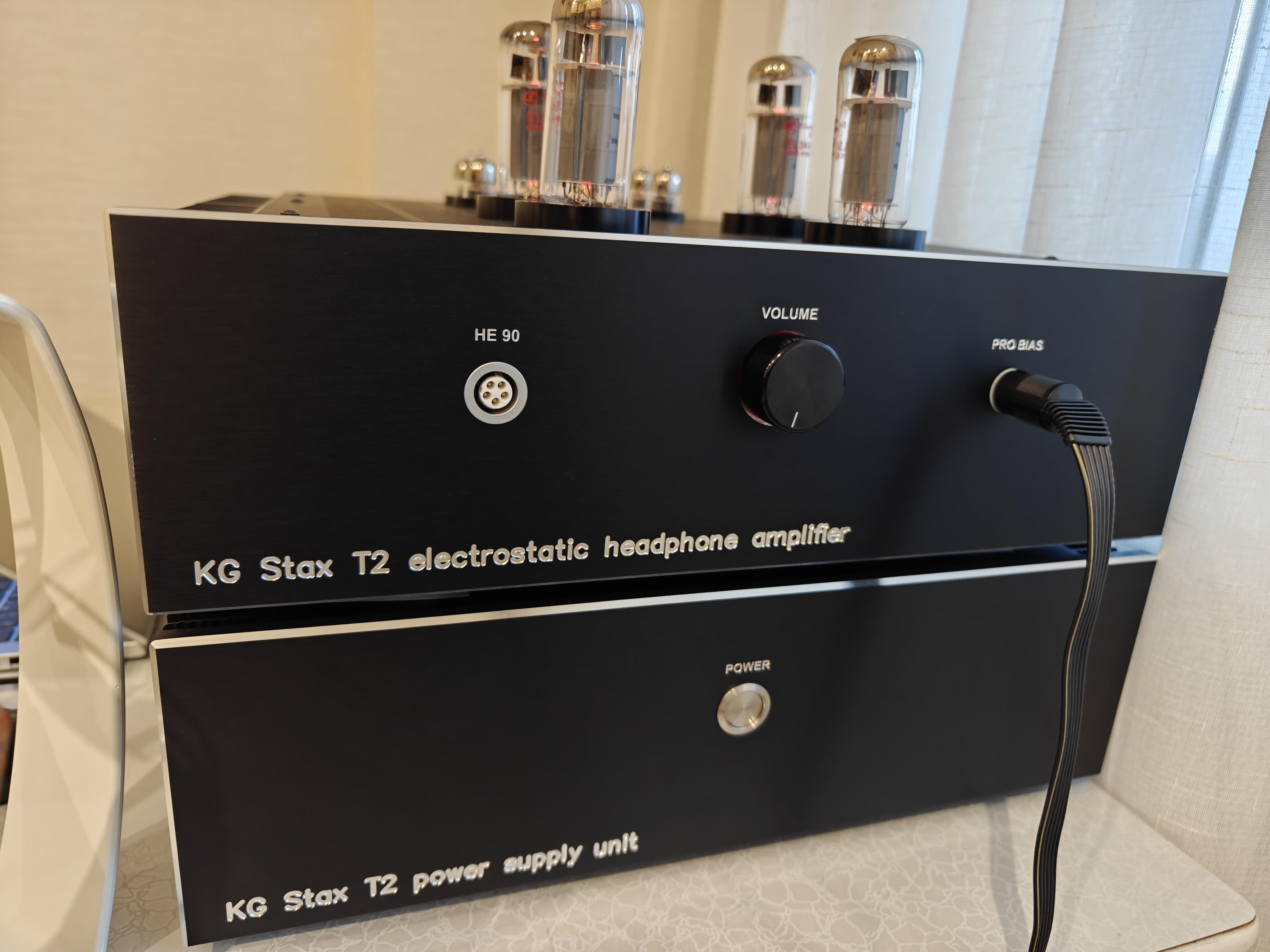
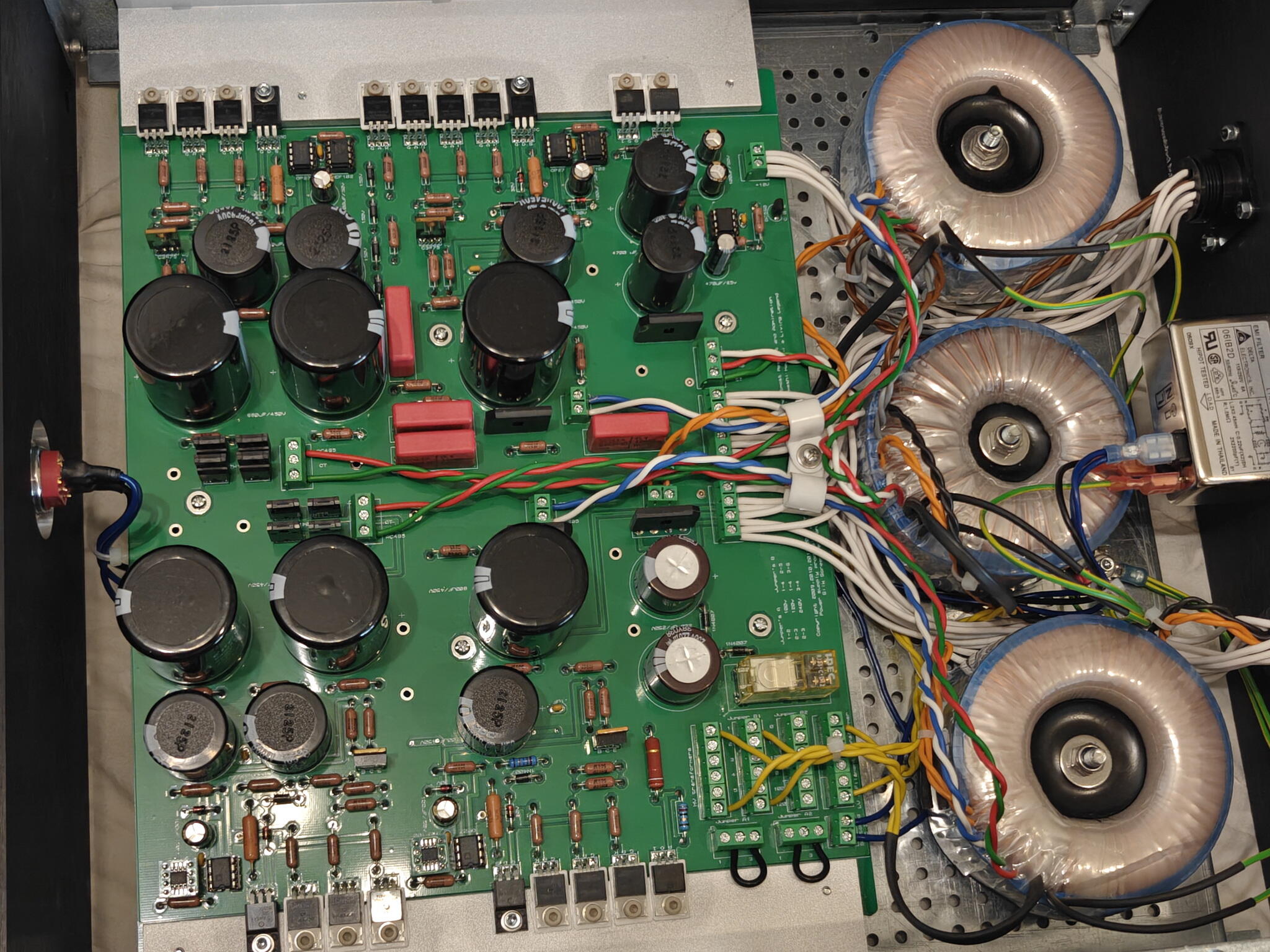
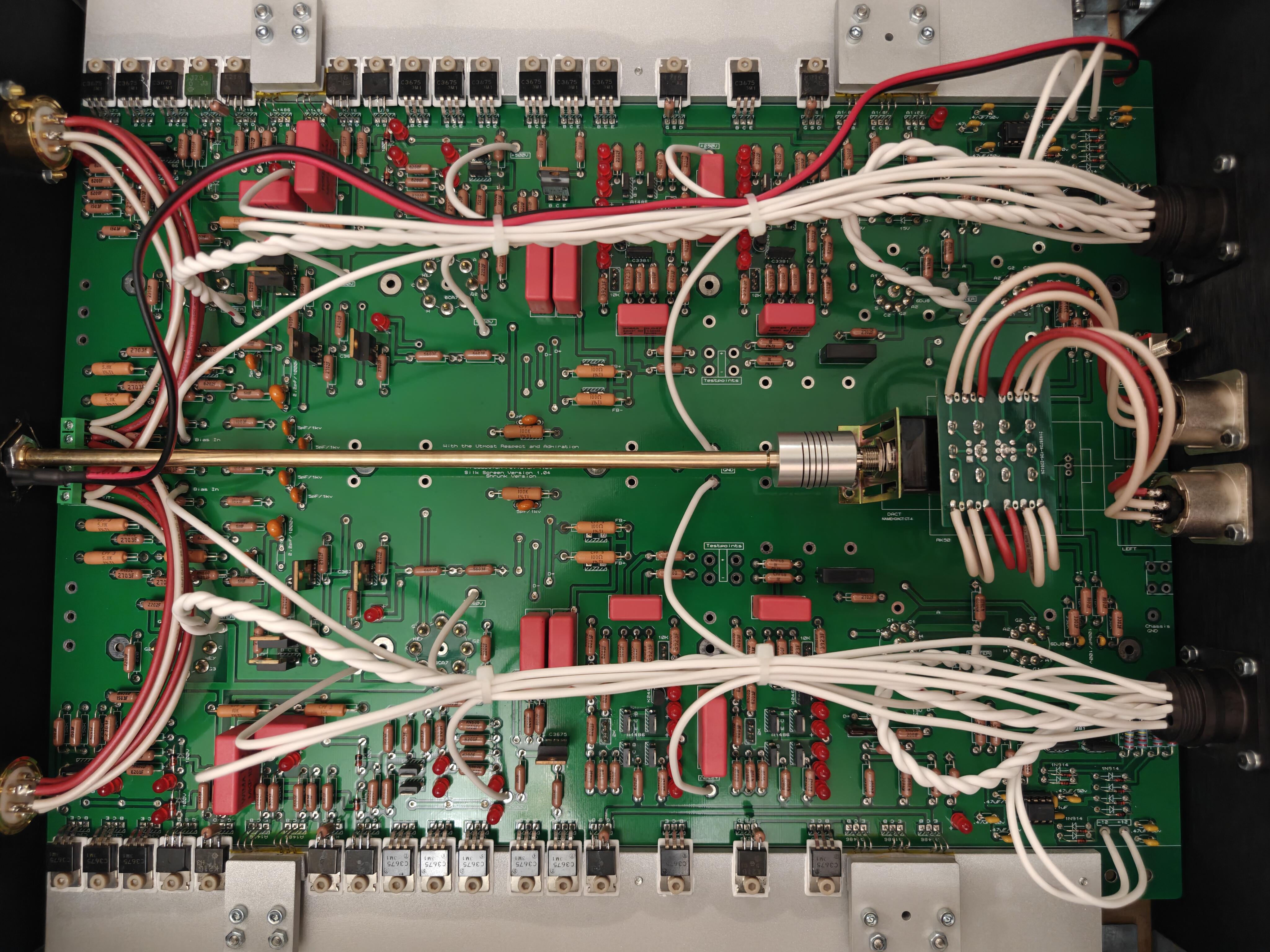
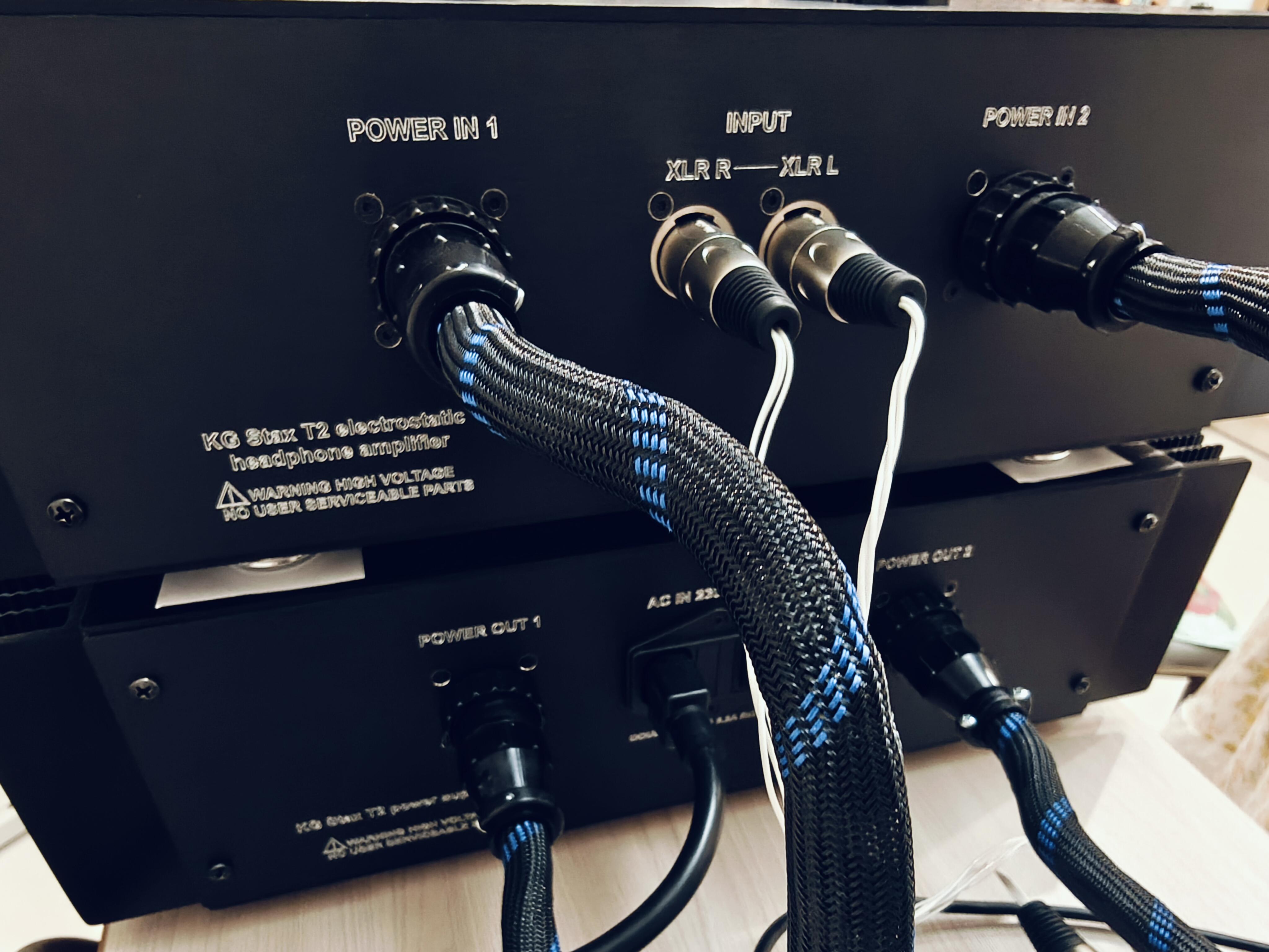
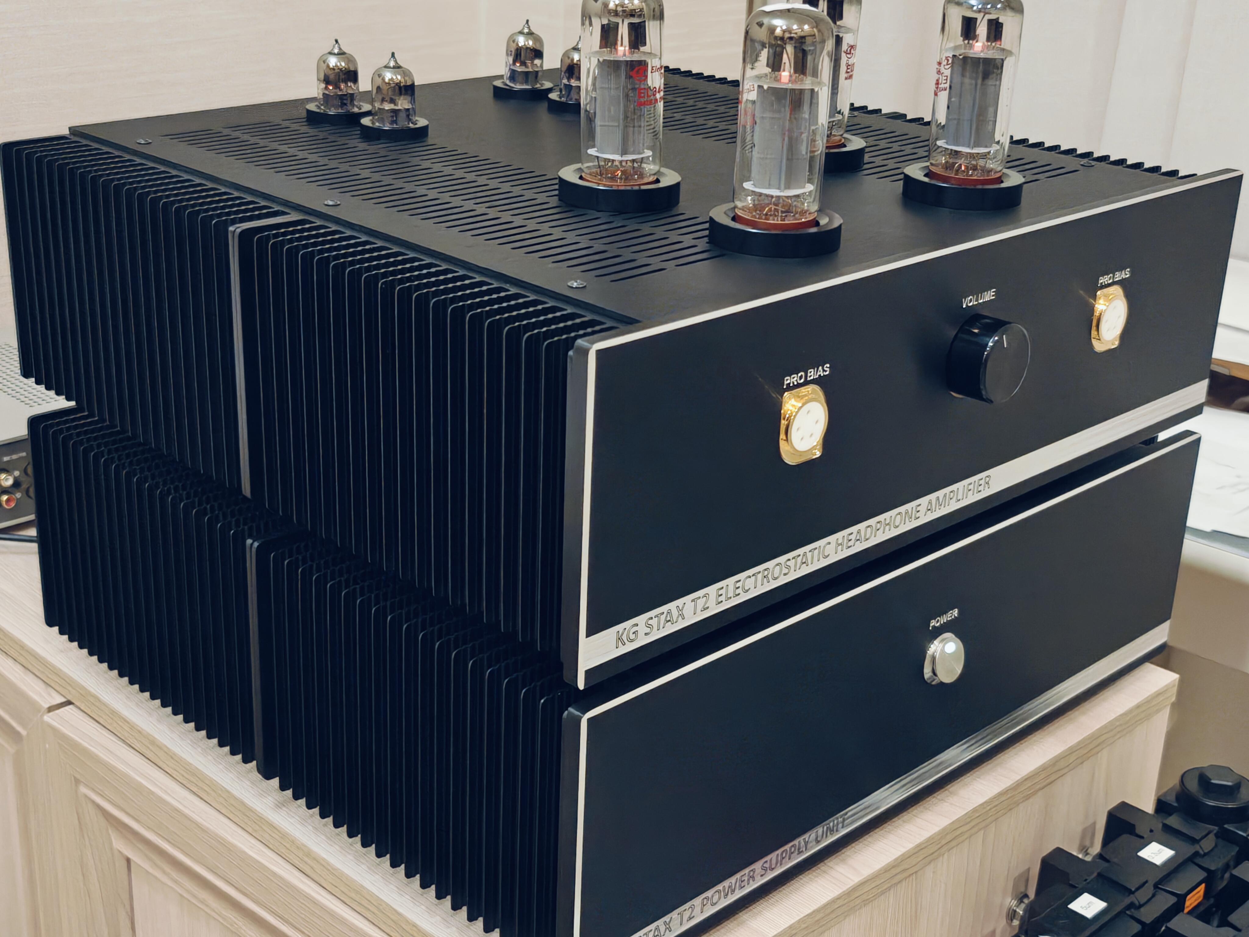
I managed to build few T2 in the past few years. Just sharing pics how T2 fits in Modushop Dissipante 400 enclosure. Many thanks to Mr. Gilmore and HC community

-
Is electrolytic capacitors reforming needed? What is common attitude to this procedure? I've got quite a few pcbs that I completed 8-10 years ago. Most projects are from amb and KG. I soldered PCBs, washed them and put aside on the shelf. But life is life, time has passed and finally I thought that this year it's a good time to complete them. Pcbs were never switched on. Caps I used are all good if not the best brands: Panasonic, rubycon, nichicon. Never frozen, never heated. However I'm confused how short the shelf life is according to manufacturers specs: 2 years, maybe 3. I remember receiving caps from mouser that are almost 2 years old, I'm curious what they do after 2 years, dispose them? Anyway, do I need to do anything about caps? Do they really degrade, or is it just a BS from manufacturers to stay on safe side? Maybe 8-10 years are nothing to worry about? I really would avoid desoldering and replacing everything if possible.
-
Edit: one idea, is maybe log taper of the pot was too steep. Need to try another one.
-
It's definitely quieter. Reasonable loudness is reached at 15-16 o'clock. Pot is 10k series type, B+/B- is 400vdc, but those don't affect volume. The only change I made is I used TTA004B,Q and TTC004B,Q instead of KSC2690AYS and KSA1220AYS. I doubt that it could be the reason as they are direct replacements. It would be nice to find a solution.
-
Did anyone experience that BH BJT is quieter than other Stax amps? Like 15 o'clock vs 12-13 o'clock on T2. Is there any way to increase gain?
-
Could someone explain the rule for choosing VAC secondaries of HV transformer? Rule of 0.707 (400VDC as target + ~10V of voltage drop = 290VAC÷0.707) doesn't apply here? Should we add 30-50VAC (or how many?) for voltage drop and regulation? Thx.
-
Thanks, spritzer
-
I've searched but couldn't find answer. Can KGST work with 450v power supply?
-
Seems that KSA1220AYS may also be replaced with TTA004B,Q? The latter also seems better.
-
Yep, I myself had to scroll this thread again as Im in the process of building one. I think the mod is referred to this post: But I dont see what resistors were XXohm value in the original design and became 33kohm in the updated design as Im building the latest rev of PS PCB (speaking of original DIY T2).
-
Can anyone please point this mod for me? I can't find it reflected in the (latest?) schematic or PS PCB. R14, R29, R41 and R53 resistors are all 2.2k, or am I looking at wrong locations?
-
Did you trim snap-in capacitors leads underneath PCB? Seems that PCB is quite low and may be touching bottom cover. Once I made same stupid mistake. Without load PSU was OK, but when I connected amp section, it exploded quite spectacularly.
-
and now for something completely different part 3
Helium replied to kevin gilmore's topic in Do It Yourself
Any specific reason why you would put tube unbal-bal converter in front of CFA? Just to make it as complicated as possible? There will be ~100 more parts in signal path, hardly they will make amplifier sound better. -
and now for something completely different part 3
Helium replied to kevin gilmore's topic in Do It Yourself
I would use different layout. Move transformers and grlvs to the front. Move cfa to the rear. Keep DC protection board where it is at the front. Use extension shaft to mount volume pot at the rear close to inputs. Side notes: move ac inlet to the left or right, it doesn't have to be on the center, it gives nothing. Stack the upper cfa higher so that transistors are distributed more evenly over heatsinks area. Move inputs closer to center (and to the pot) and move speaker terminals to outer edge of the chassis. Cause your speakers will be placed to the left and right and maybe quite far away from the amp. Consider stacking transformers on top of each other, you have 120mm clearance if you don't use steel chassis. That way you will have space to mount grlvs horizontally. After all I don't think that amp with bjt output transistors is good to drive speakers. I would consider omitting speaker terminals completely. -
and now for something completely different part 3
Helium replied to kevin gilmore's topic in Do It Yourself
Here they are. Consider 2-storey layout, where CFA boards are mounted on top with each other and to L-brackets on heatsinks. This is what I have in mind for my CFA3 project.
-
and now for something completely different part 3
Helium replied to kevin gilmore's topic in Do It Yourself
This is how 3U heatsink looks like with brackets installed.
-
and now for something completely different part 3
Helium replied to kevin gilmore's topic in Do It Yourself
Well, I myself don't like mounting trafos on aluminum plate. Dissipante comes with 3mm anodized top and bottom plates, mounted with 4 small screws m3. For me this structure is not very good to sustain weight of trafos. Moreover, if you use steel chassis to mount everything inside, you can do without any holes in bottom plate (except those for feet). -
and now for something completely different part 3
Helium replied to kevin gilmore's topic in Do It Yourself
I used modushop dissipante quite a few times. I doubt that you will be able to mount boards on side heatsinks this way. Have you accounted for steel support brackets that take up significant area of the heatsinks, and use of steel chassis on the floor? Since you are mounting transformers on the floor it's good practice to use steel chassis (sold separately) to get extra rigidity. -
Ok, no one is issuing orders (except that taking a breath can be regarded such). Why such tone?
-
Not sure if DIY forum where people come together to share interests is an appropriate place for such things. There is too much hostility and hate in life nowadays, don't bring it in here.
-
Wait a minute, are you telling that no drift is something wrong? From my experience there is some drift (0.5~1VDC without servo, and ~200mVDC with optoservo installed, both balance and offset), and I wish it wasn't there.
-
and now for something completely different part 3
Helium replied to kevin gilmore's topic in Do It Yourself
If not sold, are you going to transfer most components to split boards? Out of curiosity, are split boards so much better than wider boards to justify hard work of desoldering and soldering a lot of parts? -
Yes, same batch. Seems that Hakko 808 isn't ESD safe. Lesson learnt.
-
Did anyone experience how vulnerable DN2540N5 are? They are damaged so easily that I had to scratch my head. E.g. desolder it from a donor known good GRHV, actually new (don't ask why, I had to get spares) and it's detected OK in circuit as N-Ch depletion mosfet. I desolder it, test it and BAM it's no longer depletion mosfet, it turns into kind of Voltage regulator. And doesn't work of course. I spoiled 4 pcs already, despite the fact that I know how to desolder and handle components. And only one out of 5 was OK after desoldering.
-
I checked phase of all windings prior to connecting. Yes, they are not marked, I marked them by myself. And connected both HVs in phase. Yes, it's single -400 board. The other one (+400) is dismounted ATM and waiting for a part for replacement.