


Ariamella
-
Posts
46 -
Joined
-
Last visited
Content Type
Profiles
Forums
Events
Posts posted by Ariamella
-
-
I know
 I'm just wondering
-
Oh no, it's hitting me as to just how expensive both the GRLV and Salas BIB PSUs will be when fully stuffed...are there any other options for cheaper but still effective ones? Would, say, an LM317/337-based PSU give decent performance?
-
That would be pretty great! I asked over in the GRLV thread too, just in case.
-
Hi there. If I were to go for the GRLV, where would I be able to get boards for it? I can't seem to be able to find any at the moment.
-
Oops I meant S22, not B22
Also, I plan to use two bipolar ones, one for each board, with each side rated at 300mA output/500mA input current. Definitely won't be 1A going through each one. How would that change things? Mainly just looking for a cost-effective and compact solution, really.
Also, if I were to go for the GRLV, where would I be able to get boards for it?
-
Would a couple of the Salas SSLV 1.1/BIB be fine for powering the Dynahi or is the S22/GRLV a better choice?
-
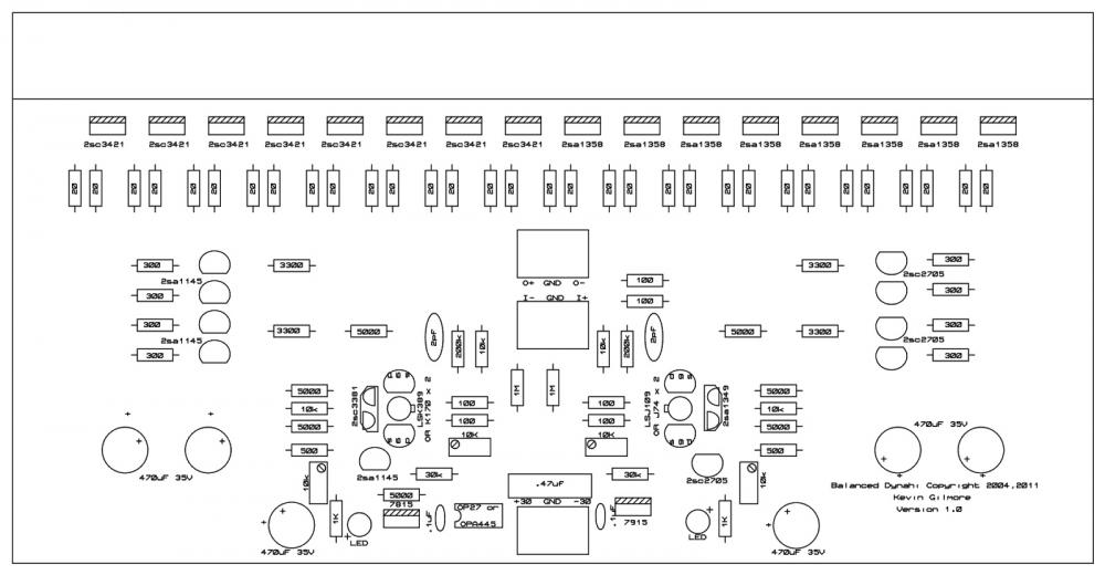
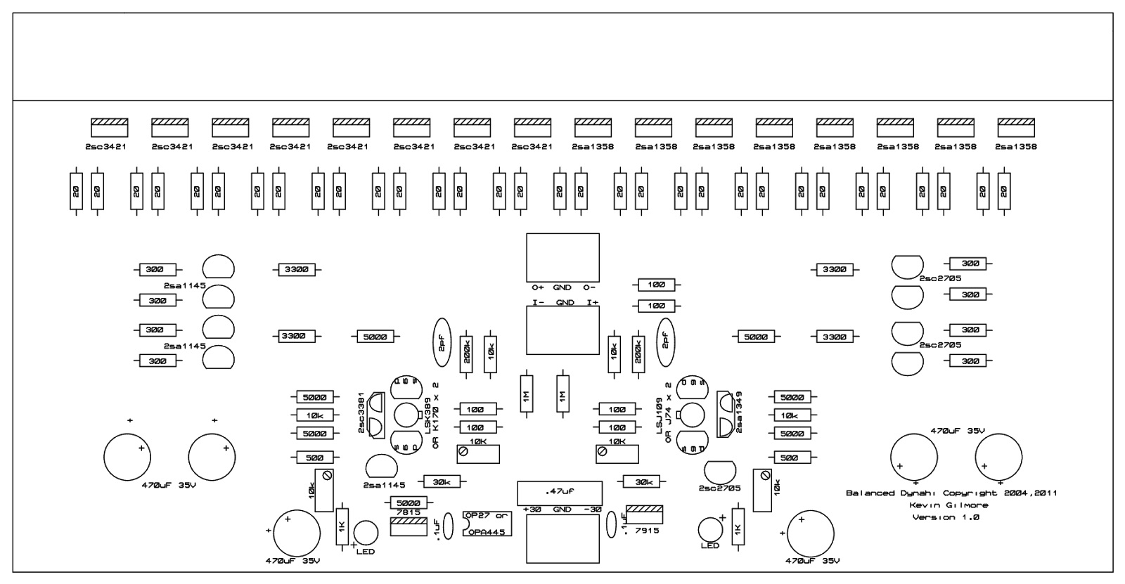
Thanks to a certain Sbleyo I now have the most up to date Dynahi PCBs! May I have a picture of the silkscreen so I can go ahead and make a new BOM?
-
Oh man that would be amazing thank you <3
-
I just got these boards...feelsbadman. I didn't realize they were outdated until after I'd already paid.
-
Ok phew I'm not imagining things then cause I'm pretty sure a couple of the boms I saw had 8 of them.
I...have none of them. Even the K170/LSK389 confuses me. If I want the LSK389 do I get the A or C grade? Etc.
I think I started off with something quite advanced here but I must persevere!
-
Which do you change? The 200kR or 10kR ones?
Also yes I'm aware of that sand, not sure what to replace those with...
-
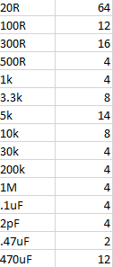
How many 5kRs do you have btw? I counted only 7 on each board...
-
Not sure where R52, R56 are honestly. Which resistors are they originally? That would help.
Also, am reconsidering the gain of 10 and I'm thinking maybe a gain of 6 or maybe 8 tops is better.
Good to know that a 10k would work! Thank you!
-
3 hours ago, Pars said:
11 is the standard gain. Without the schematic, I can’t tell you which resistors though
Oh fair enough, that makes sense.
3 hours ago, Pars said:Use 1.7V unless you feel like calculating resistor values to arrive at the design CCS currents using something else
Does it have to have the same current rating as the original chosen?
3 hours ago, Pars said:That should be fine. Use something that fits the board
Ok, got it!
3 hours ago, Pars said:Without the schematic, hard to say. If that shows the MPSWs you showed above, that could be a problem. Arrow may still have some. The nearest equivalent is the PZTA06/56, but those are surface mount. Also, I would assume that Kevin was using something more like MJE or MJF15030/15031 for the output devices?
There are a few different types that are required on the board. I'm aware that there were several different versions of transistors being used and my brain is confused as to which ones are the correct ones.
3 hours ago, Pars said:The 7815/7815 are there so you don’t have to use OPA445 for the servo opamp. If you omit them, you’ll need an opamp that can handle your +/- rail voltage.
So if you do use an OPA445, you don't need the 7x15s? They seem to be available on mouser. https://www.mouser.co.uk/search/ProductDetail.aspx?R=0virtualkey0virtualkeyOPA445AP
What kind of sound quality difference would there be between the two options, if you're aware of any?
3 hours ago, Pars said:Also, I wasn’t sure if the lil knight boards were the Super Symmetry?
The ones I got are, and I'm fairly sure they were from the first Dynahi SuSy GB? Not too sure though. Anyways, this is the silkscreen for them.
 3 hours ago, Pars said:
Sent from my iPhone using Tapatalk
I am...incredibly impressed that you managed to type that much on mobile.
Anyways, thank you for the help! <3
One more question. Would a 10k pot work for the input? I read some stuff about the input impedance of this amp being low and stuff but I didn't fully understand it...
-
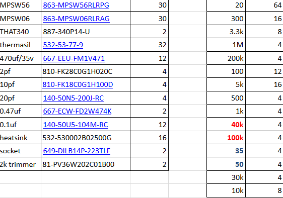
So, well, I was trying to compile a BoM of the original SuSy Dynahi 1.0 PCB from 2011 and there are a few discrepancies between the published BoM by Lil Knight and what I can see on the silkscreen, when it comes to the passive non-adjustable components. Which version is correct?
My rBoM (left) VS Lil Knight's (right):
Apologies but I have a load more questions!
Where would be the resistors be that control the gain? I'm finding myself unable to find them...ideally I'd like a gain of roughly 10. What values of resistors and caps would this require? (Something like 11 or 9 would work fine).
Does the current/power rating of the red LEDs matter and do they have to be rated at 1.7V or would 2V work?
Would using 1000uF caps instead of 470uF work like I've seen some people in this thread do?
What would be the closest still available replacements be for the various transistors on the board?
Are the 7815s and 7915s necessary?
Think that's about it so far...thanks for bearing with me!
goldenreference low voltage power supply
in Do It Yourself
Posted
For 30VDC output, would a 25VAC or 30VAC transformer be better, out of the standard ranges? I'm pretty sure it's 30 but just wanted to make sure first.