Pflugshaupt
-
Posts
11 -
Joined
-
Last visited
Pflugshaupt's Achievements
Member (2/6)
7
Reputation
-
Yes it's to get rid of resonances while handling the headphones or tapping them - or moving your head. These are 3d printed parts with a layer of sorbothane sandwitched in between. They were inspired by a thread on another forum, can't remember where - but google can find it if you look for stax 007 sorbothane damper.
-
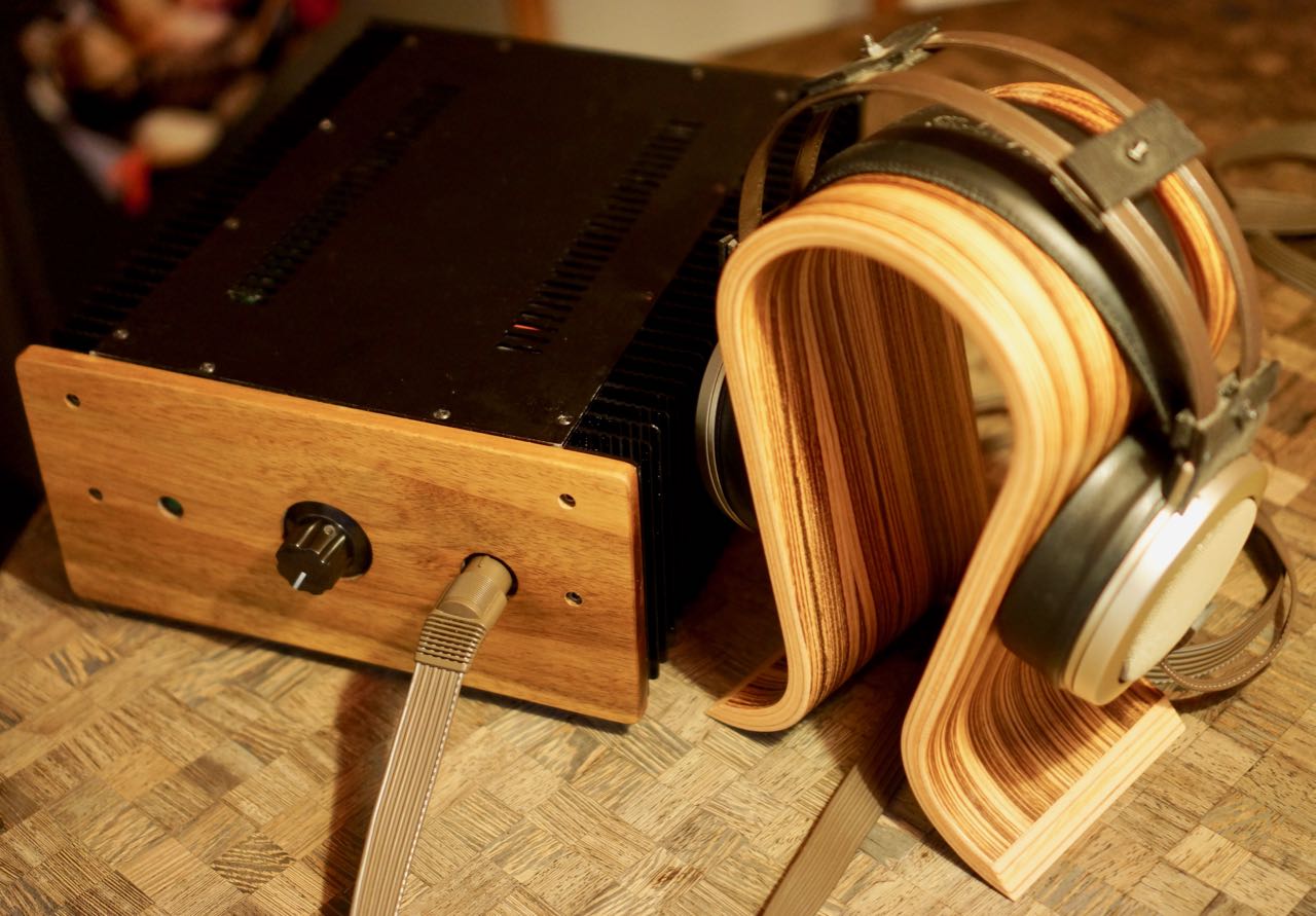
Not sure what you mean by yolk.. part of an egg? Sorry.. I'm not a native english speaker. Do you mean the color? It's a very early SR-007 mk1, so maybe it has seen many more hours of sunlight than most. The ear cushions and the headstrap had the same color - creamy brown, but I replaced those due to previous owner perfume smell ;). I added a few dampers to combat the ringing when the headphones are touched.
-
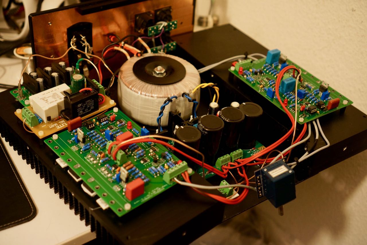
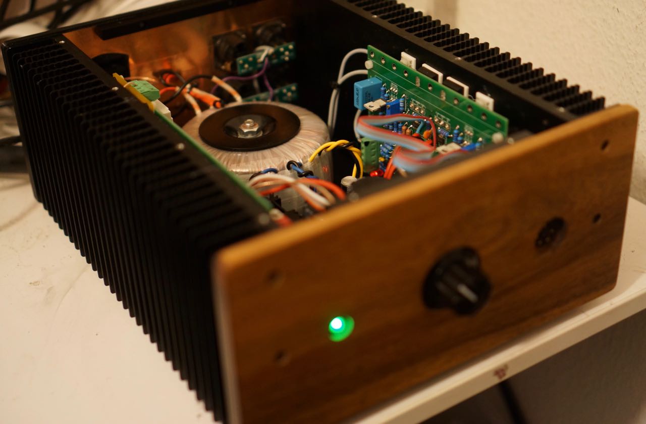
The ones I broke I had ordered from mouser when they still were available - like everything else in the build. However my psu was not made by me and I have no idea where those parts came from. I still don't understand how the mosfets could break down completely. I read up on mosfet failures and what I got seems to come from overvoltage. However I have a 400V psu that became unregulated on the negative voltage and it never surpassed -460V... anyway very happy it works again. I realize ebay is known for fake parts and I would never buy truly rare parts from there like those K170. But I took my chance with the c2m as it just became hard to order recently and isn't obsolete yet. I also received the UnitedSIC parts from mouser, but without more opinions I didn't want to try putting them on my board. Here are some images. I cnc'd a front panel from future carbon (acazia wood). The extra boards are a 3-stage dc filter and a relay/resistor-based inrush limiter. My old house with strange wiring has quite some dc and it made the transformer hum constantly. The PSU is the standard BH-mini-psu circuit. I increased the cap size when I replaced almost everything on the board.

-
I received new c2m1000170d I bought on eBay from Honk Kong for $7.50 per piece. The eBay images looked a bit strange, but the parts that arrived looked and felt absolutely identical to my broken ones. They measure infinite resistance between G & S on my meter and so I built them in and now my amp is working again! Will post some images tomorrow.
-
Thanks, I did that already and one c2m1000170d measured very low. I then managed to remove that one. Unconnected, resistances are much higher and appear to be correct. Even with one removed I still measure only 50k between B- and B+... so I'm beginning to think there's just a short somewhere on the board or in the board itself but I have no luck finding the issue. I did triple check below the center terminal and applied generous amounts of nail lacquer as I read about shorts in that location somewhere on this thread. I already ordered the UnitedSIC part, but now I don't think the problem is the mosfets. As there are many test points on the board, is there a guide somewhere how to use those? Edit: I guess I confused k & M on my meter late at night . measuring again I'm quite sure the part I removed was indeed broken. G to S resistance is 2.6 kOhm 🤨. But now I'm wondering how much it should be on a healthy one? The other one on my broken channel measures 0.4 mOhm, while the two on the "good" side measure 5 mOhm and 9 mOhm. I'm kinda scared my broken psu might have destroyed all four of them and theoretically it should be infinite.. right?
-
Brace for newcomer problems.. sorry. After a lot of struggle I managed to fix my power supply. It had a multitude of issues, but now it finally produces all the right voltages again. So now here I am again with one working and one broken kgsshv carbon channel and not much of an idea how to fix it. In the meantime I received spare parts for most things. I inspected my faulty channel at length and resoldered some stuff to be sure and then decided to fire it up with the +-15V rails. This appears to work fine. I voltage-compared all the test points between the two channels and they were very similar. Then I tried to compare resistances between the high-voltage parts of the channels. I saw some differences here, which most likely means at least one part is broken. F.I. the resistance between B+ and the via next to the terminal block is only 250 kohm on the broken channel, while is is over 1.5 mohm on the good channel. I did replace the PZTA42 next to that. Foolishly and because I didn't know how to go on, I decided to fire up the full voltages. aaaand.. magic smoke. At least I know one thing that's broken now. It came from the 20k resistor connected to B- and I guess that's really a bad sign. I fear what is broken is at least one of my c2m1000170D. Of course the part that is the hardest to desolder for testing and has also became unavailable recently :(. If the 20k burns.. could anything else than the c2m1000170Ds be the problem? They look so sturdy.. but do they break easily? Update: in the meantime I replaced a couple both PZTA42 and two PZTA06, but resistances do not check out. I measure 51.7kohm between B- and B+(1.3 mohm on the healthy side) and turning it on would produce smoke again.
-
Thanks a lot for your help. I'll report back once I got my mouser order that went accidentally to Canada instead of Belgium :o. So maybe not tomorrow :). That will most likely allow me to fix the power supply and maybe this will take care of the issue already. LV +-15V is still working fine. I do have a scope, but I don't really know what to measure to diagnose the issue.
-
I desoldered and tested my 2SK170s and they seem to be fine. In the meantime I figured out the problem with the PSU. One of the voltage limiting zeners was broken and B- was no longer limited to -400V and went to about -450V, but probably not stable? Tomorrow I'll get some replacement parts and that will hopefully fix the PSU and give me options to replace things on the left channel. If B- goes wild, what is the most likely part to break? Nothing looks slightly burned besides maybe one of the PZTA42, but that may be flux from the build. Maybe it'll start working again once the B- is correct again. That would also explain why I get sound during turning on/off as during that time the voltage drops. On the other hand, the right channel didn't break so something has got to be off on the left.
-
My best guess is that I accidentally destroyed one of the 2SK170 on the left board. It unfortunately got bent once and I bent it back and after that it was still working, but maybe now the vibrations have killed it. Could that explain the strange behaviour I'm seeing? (running half-ok with -15 V disconnected, but only strange static with +15 and -15). As the 2SK170 are hard to obtain, I have no spare one to try (yet). I also get a few seconds of sound when turning on or off, but as soon as voltages are stable, only hum/static/crackles and a whole lot of silence in between.
-
Answering myself - I figured the -430V is a PSU problem unrelated to the sound/crackeling/voltage drop after the 20K resistor.
-
Hello forum. First of all thank you all a great deal for creating this forum and of course heaps of thanks to Kevin Gilmore and the other designers for creating these wonderful amps and to everybody here for sharing their knowledge for everyone to learn. I read through a lot of this thread and recently finally finished my own kgsshv carbon. It is based on chinese ebay amp PCBs, the BOM from this thread, is running on a 400V kgbh-PSU I already had and was sounding great for several weeks until I messed up something this morning and now have a very hard time troubleshooting. I might have mechanically damaged a part or maybe temporarily not connected things correctly, but now I'm facing very strange output and thought maybe someone came across this before. My right channel is fine, but the left one suddenly produces some hum as well as weird static noises that change over time and no more music.. just some sort of occasional crackling. For some reason my B- now measures -430 V (was -407 V before) and I measure over 100V voltage drop on the 20kohm resistor connected to B- which is a lot more than on the right channel. Now the strange thing I randomly came across: If the -15V input is disconnected, I get music and it seems to even sound somewhat ok. Does this make any sense? What I did before things broke was causing vibration to the board, so maybe something is loose. I also might not have -15v and 15v connected correctly initially when starting up again.. could that cause damage? Thanks for any help, I'll go on comparing my two sides to hopefully figure it out, but any pointers would be very welcome!