


mwl168
High Rollers
-
Joined
-
Last visited
-
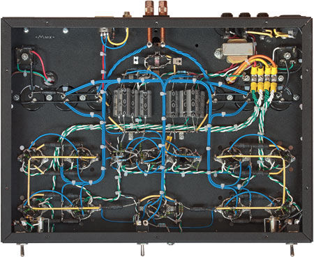
There is no reason hand-made, point-to-point wiring cannot be done right.
-
-
Here are a couple of posts in Audio Asylum from the late Mr. Charles Hansen (founder of Avalon speakers and later Ayre electronics) where he illustrated the history and inner working of HDCD. There are many more related posts you can find in Audio Asylum. I found them both educational and very interesting read. https://www.audioasylum.com/audio/digital/messages/18/184385.html https://db.audioasylum.com/mhtml/m.html?forum=digital&n=184436&highlight=HDCD+pacific+charles+hansen&search_url=%2Fcgi%2Fsearch.mpl%3Fsearchtext%3DHDCD%26b%3DAND%26topic%3D%26topics_only%3DN%26author%3Dcharles%2Bhansen%26date1%3D%26date2%3D%26slowmessage%3D%26sort%3Dscore%26sortOrder%3DDESC%26forum%3DALL
-
-
Happy Birthday, Chris!
-
RIP, Karen. My deepest condolences!
-
I am exhilarated. I have an Oppo BDP-83. Good to know it's worth $3500. Anyone interested?
-
If you are willing to shell out the cash, there are also the options of the Magnetar players... https://www.magnetarusa.com/
-
-
Happy belated birthday Kerry! Hope you had a great time.
-
Maybe try to swap the left and right channel boards and see if the hum follows the PCB board?
-
So EL34 for the CCS tubes and EMS 20B for the output tubes? Any other modifications needed other than accounting for the 20B filament supplies?
-
Apart from this audiophile scene, this is a great movie. This particular one is the second of a trilogy. The first of this trilogy is what the movie “Departed” is based on.
-
Did the PSU blow up while in play or at power-on?
-


