ShortBtwnHdset
-
Posts
16 -
Joined
-
Last visited
Content Type
Profiles
Forums
Events
Everything posted by ShortBtwnHdset
-
goldenreference low voltage power supply
ShortBtwnHdset replied to kevin gilmore's topic in Do It Yourself
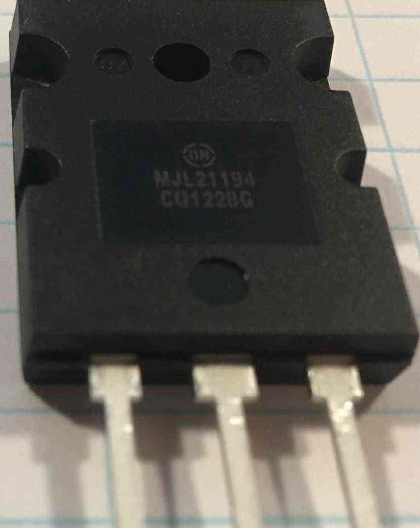
Pars, you are the 'Man'!!! Thank you! Ordered tonight! As to the other two transistors, here's a pic of the better looking of the 2 (1st is a little scratched up). Part numbers are printed clearly, not stamped or engraved, and the lettering in the dots is very clear and either stamped or molded, 07 and E for MJL21194 and 03 and E for the MJL21193. ETA on backorders is Dec and Feb if the current ones are fakes.
-
goldenreference low voltage power supply
ShortBtwnHdset replied to kevin gilmore's topic in Do It Yourself
Ok, quick update. Finally received transistors/FET's from flea-bay purchases, 12 - KSP42TA from Spain, and a complimentary pairing of a MJW21194G and a MJW21193G from Germany. The Question is are they fakes? I have an offer for someone who has the capabilities. Could I get someone to test a sample of 4 of the KSP42TA's to see if they match up to spec, and they get the 4 free for the service? They would obviously need the equipment to properly verify specs. It seems to take a minimum of 4 for this board, and they should still be able to get the KSP92TA's from Mouser current stock. Anyone game? Would prefer continental US as I'm paying US postal. Hoping to get some pictures of all three posted, so if anything obvious looks off ya'll might alert me. Back orders from Mouser look abysmal right now, some slated for as late as march of next year. In other news, I did order the Haako soldering station and 2 extra beveled tips, should be in tomorrow. It's looking like I may have to put off continuing on this board and start instead on the SuSy Dynalo boards to keep making progress. Will probably start a resistor order next week. Anyway, have a great night/day!!! -
goldenreference low voltage power supply
ShortBtwnHdset replied to kevin gilmore's topic in Do It Yourself
Thank you Pars! -
goldenreference low voltage power supply
ShortBtwnHdset replied to kevin gilmore's topic in Do It Yourself
1/2 watt on the resistors? And 250V on the caps? -
goldenreference low voltage power supply
ShortBtwnHdset replied to kevin gilmore's topic in Do It Yourself
Hey all! Pars, you have a post early in the thread, around page 4 I think, where you used rectifier boards and Schottky's instead of large bridge chips. There is a .002uF cap and a 330 ohm resistor in the pic, might I get values (voltage/wattage) and/or PN's for those? Bought rectifier boards from Partsconnexion, and want to tack those on to each, so need similar compact parts. Thanks! -
goldenreference low voltage power supply
ShortBtwnHdset replied to kevin gilmore's topic in Do It Yourself
Hey all! I had gotten the .1% resistors per your suggestion, so will probably go this way. I used to have a great temp controlled digital display soldering station, bought surplus from an aircraft tool shop, but it degraded over time to being unusable, and the 45 watt was originally a 'get by' purchase for a project. I'll have to investigate the Hakko, what I'm using currently just isn't working well. I already have a de-soldering station bought for my last project, but I use solder wick as well. Neither seem to totally remove all solder enough to get the components back out in one shot, so maybe I am using some non-leaded type. Until you and Pars mentioned this, I didn't know it was a 'thing'. Pars, as to where the boards are from, I really don't know, it was an Ebay purchase. Solder is regular electronics grade solder, thin stuff, but I have no idea of the composition. Seems to be slightly thicker than a mechanical pencil lead. I'll have to look online for leaded thin solder to be sure. -
goldenreference low voltage power supply
ShortBtwnHdset replied to kevin gilmore's topic in Do It Yourself
Hey all! Quick question, James' guide shows a mouser project list (BOM) link, and in that are trimmer pots, 500K. The schematic shows 100K pots. Which should I order if I want that capability? Status update, I started populating what transistors I had and few other parts. Found I had put one of the tantalums in wrong orientation, and in removing it, ended up melting one of the tiny film caps, so will have to replace it as well. Was able to get the tantalum out without lifting the solder pad, hope I'm as lucky with the film cap. Friend advised me to sacrifice parts instead of reusing them, in service of saving the motherboard pads. I'm still having some issues with using too much solder, have one transistor where a leg on the other side collected a small blob. Will try and solder wick that off. I'm using a fairly coarse (read big) soldering iron, so that may be a contributor. It's a larger iron with a temp range adjustment, about a 45 watt max, so the tips kinda large. May need to buy a smaller tipped soldering iron/station for this build. I have ordered the MJW21194G and MJW21993G as a pair, as well as the KSP42TA's off of ebay. Coming from UK and Germany; this pandemic has really screwed up supply chains. Mouser notified me backorders would be as late as January, so I needed to do something. Hopefully, they're not China knock-offs, but we'll see. Will still be up to 3 weeks before all those are delivered. Once the transistors are in, I'll populate the large caps and connectors. Won't be getting the transformer until I'm closer to having board fully populated. That's all I've got for now. Have a great day!!! -
goldenreference low voltage power supply
ShortBtwnHdset replied to kevin gilmore's topic in Do It Yourself
Hey Pars and mwl168! Thanks for the heads up, will definitely investigate! -
goldenreference low voltage power supply
ShortBtwnHdset replied to kevin gilmore's topic in Do It Yourself
Just wanted to give a little update. Progress has been made, the board is partially populated with IC sockets, most resistors and diodes, and some tantalum and film caps. All those transistors included in my ebay purchase end up only for the SuSy Dynalo boards, so I made another order with Mouser last night. MJW21194G and MJW21993G have been out of stock for a while, may have to find another source (Digikey out as well). KSP42TA's are out as well. This is my first build, and my soldering skills were tinkerer level at best. I had no idea how rusty I was! As IC sockets were center of board, I started with those, and it took a redo of a pad or two to get the hang of it. Glad I bought flux cleaner! I definitely am not of production level skill, but all of the joints now look good under a magnifier. Hardest part seems to be using just enough solder and not too much. Have bought liquid flux for the IC sockets, wasn't really a problem here but looks like it will be necessary for large IC sockets on SuSy boards. I need to start looking at transformers, hopefully toroids. Problem is, I may actually need another secondary winding and associated DC board to power peripherals. I'm hoping at some point to add options such as input sensitivity, remote volume, or multi-source switching. Do you think a 12 volt rail, maybe half an amp, should cover those capabilities? I'm hoping to start looking in goodwill shops for a temp case, repurposed from some other audio component. Just basically need the sheet metal and the IEC outlet (hopefully w/fuse holder), maybe a mount for the volume control, and even a possible input connectors or two. I'll permanently case when I've gotten everything working and have a picture in my head of the finished product. I have to look thru a lot more of everyone's builds for inspiration. More to come! -
goldenreference low voltage power supply
ShortBtwnHdset replied to kevin gilmore's topic in Do It Yourself
Well, made my first order to Mouser. They were temp out of the one or the other large ouputs, so I didn't get either yet. Still will need to get them, transformer , case, etc., but this should get me building. I'm excited!!! -
goldenreference low voltage power supply
ShortBtwnHdset replied to kevin gilmore's topic in Do It Yourself
Thanks, for all who posted! Looking at specs on these electrolytics, its surprising how few hours their rated at!😲 I never realized they were that low. Obviously we have many electronic components that have lasted longer than 1000 hrs, so those ratings must be at some percentage of rated specs, but it does make me wonder! The variac will be dual purposed, as I have several pieces of audio gear that have been in storage for years. I'm sure the electrolytics in my amp and CD player will need reforming. My preamp thankfully doesn't use them (If I remember right). Went from home to small apartment living, and just don't have room for my home system. My speakers also haven't aged gracefully (Apogee Stages). I got into the audio bug again with headphones because it's a lot easier space wise to manage. I'm thinking if I can do a test load using cement resistors at about .25 amp, that should be fine. 20V/.25 amp equals 80 ohms, 20v X .25A equals 5 watts, this should do https://www.mouser.com/ProductDetail/Vishay-Dale/RE65G80R0C02?qs=sGAEpiMZZMtlubZbdhIBIO9u8NSWRDaQ0Ik%2Fvj6PQ48%3D . Anyway, thanks again gents! -
goldenreference low voltage power supply
ShortBtwnHdset replied to kevin gilmore's topic in Do It Yourself
Thanks, Pars!!! -
goldenreference low voltage power supply
ShortBtwnHdset replied to kevin gilmore's topic in Do It Yourself
Hi all! Been reading jamesmkings' build guide, trying to understand the project before me. Please forgive me in advance for a lot of stupid questions. 1. Reference voltage is mentioned throughout, as opposed to desired output voltage or RMS voltage after the bridge or even voltage off the primaries. What in the heck is reference voltage? Where is it measured? My specific build is +/-20 volt rails for an SS Dynalo. 2. The 100K output trimmer pots. Some of you seem to use them to closely match + and – rails. Some of you don’t, it seems for reasons of temp stability or drift? Is that really a big issue here? I can purchase 1% resistors, and like James’ reference design use higher end R7-10 resistors as he did. What I really don’t have any control over is how well the transistors are matched, nor the diodes (my handheld meter (4 digits) has a diode checker, and that’s the limit of the sophistication of my tools). It seems with these limits trimming would be a joke. What gains other than satisfying my OCD nature are had by buying a 7 or 8-digit multi-meter (hopefully with a transistor checker), and at what cost to go from good to very good? 3. The 4.7uF film cap, parallel to the 220uF electrolytic. That’s a bypass cap, right? A way to get the benefits of a better sounding film cap while the 220uF does the grunt work. If I remember right, bypassing increases the range of frequencies of ripple/noise shunted to ground, but I may have that wrong. It’s approx. 2% of the 220uF. Being that those are what supplies the boards after the GRLV, is there any major disadvantage to bypassing the 4.7uF cap as well, other than fitting it on the board? ( https://www.partsconnexion.com/AURIXO-79184.html ) 4. James mentions after unloaded tests with a variac to use an electronic DC load. I’m already going to have to buy a variac, I’d like to save some money, plus I wouldn’t have to learn to use something else. Instead, can I get a pair of cement resistors, and if so, what approx. value? 5. On the variac, you can purchase cheapies off ebay for $50, but you can also find used ones that look better built. What’s a good bargain for a used variac, and what names should I look for? Thanks again, and have a great day/night! -
goldenreference low voltage power supply
ShortBtwnHdset replied to kevin gilmore's topic in Do It Yourself
First off, let me say THANK YOU!!! JamesMKing, wow, you went really over the top on this and made an amazing guide! I hope many will benefit from it. I know I definitely will! I'm going to read thru carefully and make an order for the first parts tonight. Thank you again! Also, thank you to mwl168 and JoaMat. The experience all of you guys have invested in this thread is a really nice resource to have. -
goldenreference low voltage power supply
ShortBtwnHdset replied to kevin gilmore's topic in Do It Yourself
Thank you to both Pars and Gepardcv for your posts. I do appreciate it. It seems when this thread was active, and when Kevin was involved, a lot of ya'll worked out the kinks and got a lot of great PS's made. But since the fervor has died down and the web links eventually were outdated, this design doesn't have as active a community supporting it. I realize I'm both late to the party and have probably over-reached. I've tried to read thru all 27 pages of this thread, but there seems to be no working link for a schematic for the GRLV in any version, nor a BOM or even parts list to go by since the .edu links went down. Pars has broken links on pg 25, and the google docs pages don't seem to show either, just the board layout/manuf files for this and many other projects. I can piece some of it together thru the thread, but for instance, what wattage resistors do I get, 1/2 watt, 1 watt, etc. Do the electrolytics need to be polarized? I don't see any mention of what bridge rectifiers your using, and is it 1, 2 or 3 (I think its two, depending on transformer, but that's yet another series of questions)? Or is there a supplier for the schottky mini-boards? There is just so much information to read thru, and most of what I read I don't understand. Pars seems to have built a GRLV with 20V rails to power a SSDynalo, so I can glean some from his and other posts, but that leaves me in the dark on an awful lot. I don't want ya'll to hold my hand, but working without a schematic and a parts list at minimum seems ludicrous. Can ya'll help me out? PS: forgot to mention I think my board layout is the goldenreference6.zip version -
goldenreference low voltage power supply
ShortBtwnHdset replied to kevin gilmore's topic in Do It Yourself
Hello! First post on these forums; joined when I became interested in the Dynalo while web-surfing. I really need help, as I think I've bitten off more than I can chew. Bought a pair of SuSy Dynalo boards and this PS board off of Ebay with included, fairly well matched transistor sets (https://www.ebay.com/itm/334044891985). Finally received them mid week. Version number for the GRLV board is .44, for the SuSy boards is 1.1. I've tried to no avail to follow the page1 links from Kevin at the .edu site to try and get schematics and BOM for boards, but my browser keeps timing out (from America). Getting the board manuf files doesn't seem to be a problem, though, as the links work. I've read through many but not all pages of this and the "and now for something completely different part 3" threads, and am currently overwhelmed by it all! It sounds like I need to start with the PS board and what general parameters I want my build to have. So I guess I need a target voltage for powering the SuSy boards, a schematic for this GRLV board, and a BOM for this board to start. Also, which PS thread and Dynalo thread should I follow for the build? Progress on this will be slow, as I have several LT home projects happening as well. I have basic electronics knowledge, am handy with a VOM and a soldering iron, and I'm handy with hand tools, but nothing beyond that. I've never built one from the ground up. Have I screwed up buying this? Thanks in advance for all replies.