micon21
-
Posts
70 -
Joined
-
Last visited
micon21's Achievements
Limited Edition Bronze Participant (4/6)
8
Reputation
-
Pars Thanks for the link to RM. I’ve been registered there for a long time, but I didn’t know they were selling the 216. I bought the 216 and 79 on eBay in 2020. I was building a T2 in 2024. But the board didn’t work. Most likely, the 216 and 79 weren’t original. Replacing them with TA004 didn’t help. When RM sends me the old 216 and 79, I’ll try to get this model running again. Right now, I’m happy with the modified version. The boards are from KGSSHV Carbon, but I replaced the C2M1001700 with EL34 tubes.
-
A small factual statement. I saw in the thread that forum members are also using inexpensive EL34 models, like the Tung-Sol. There are photos of German RFTs and Russian Mullards. I currently own all of the listed quartets. When listening, I noticed that the Mullards (2015) sound significantly better.
-
to achieve additional truth, I bought a device that was recommended to me on our forum - DUOYI DY294. I am waiting for the arrival of both DigiKey and Ali
-
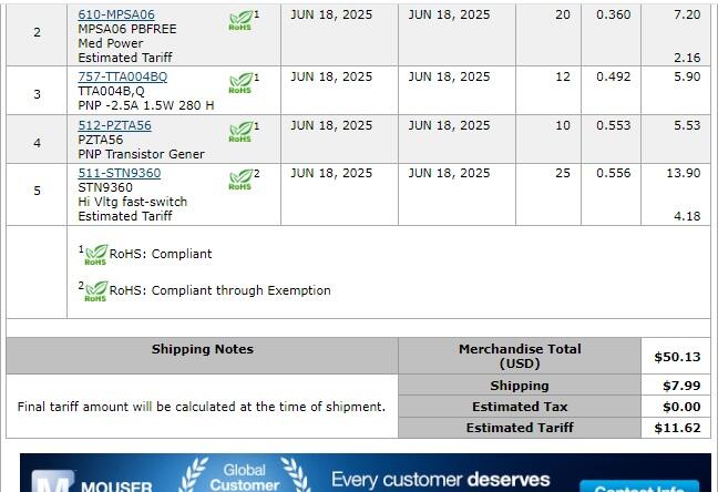
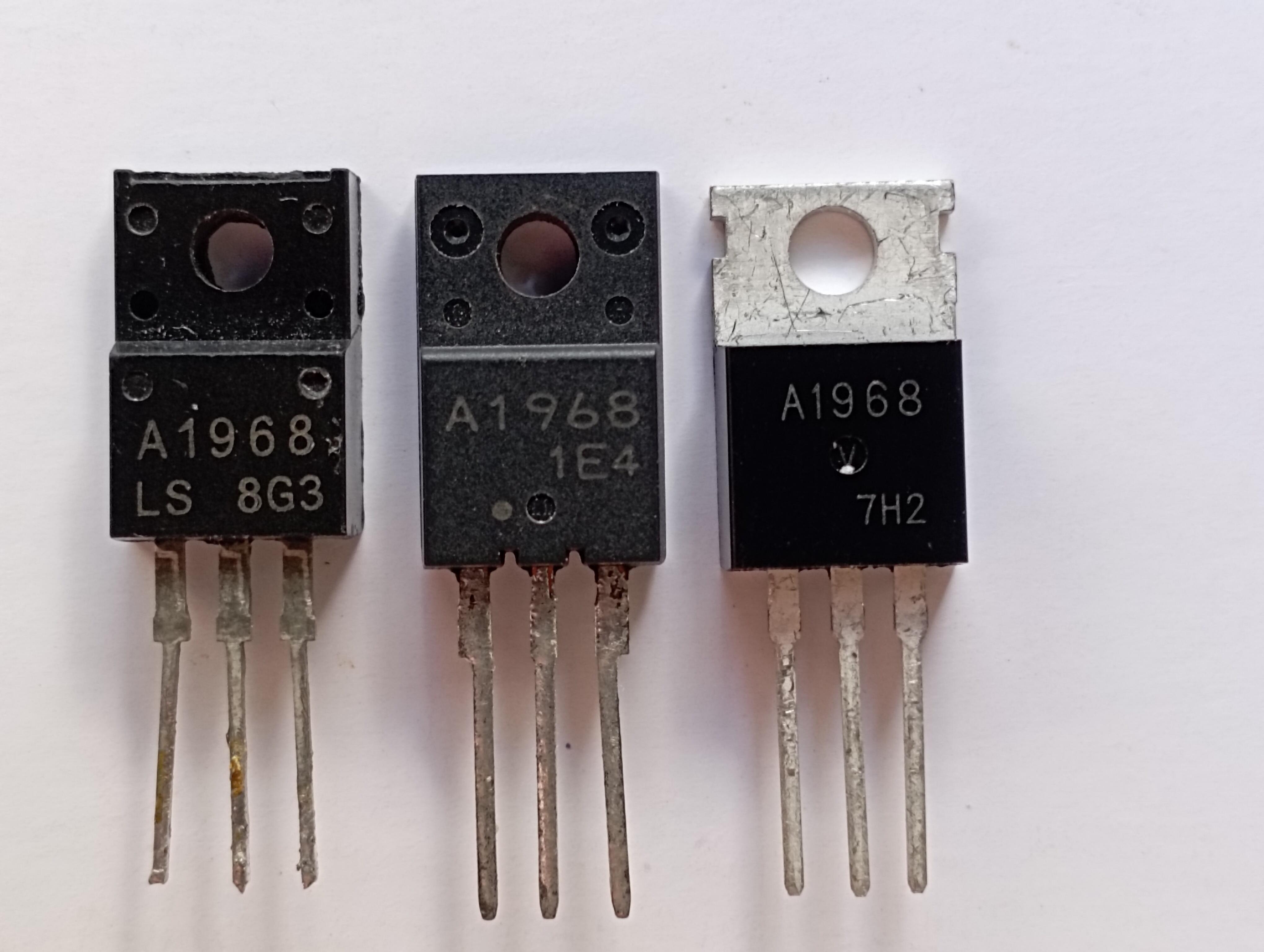
I showed you a photo of the transistors and the gain of the transistors that arrived. I am NOT happy with the big difference in measurements between the datasheet and what I see from the transistors from Mouser. I spent extra money for comparison. I made a test purchase from Digi. I will write the results.
-
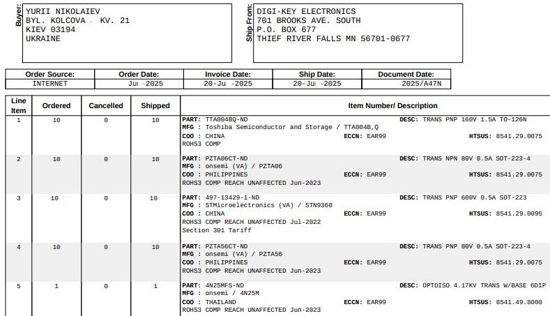
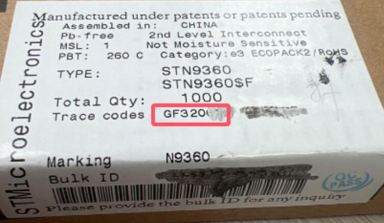
I warn you in advance. I am not happy with the purchase from Mouser. I bought several parts from digikey - 9360, 004, 06, 56. They will arrive around August 11. I am very interested in what I will see on the 9350 case, and what the device will show - in hFE mode.

-
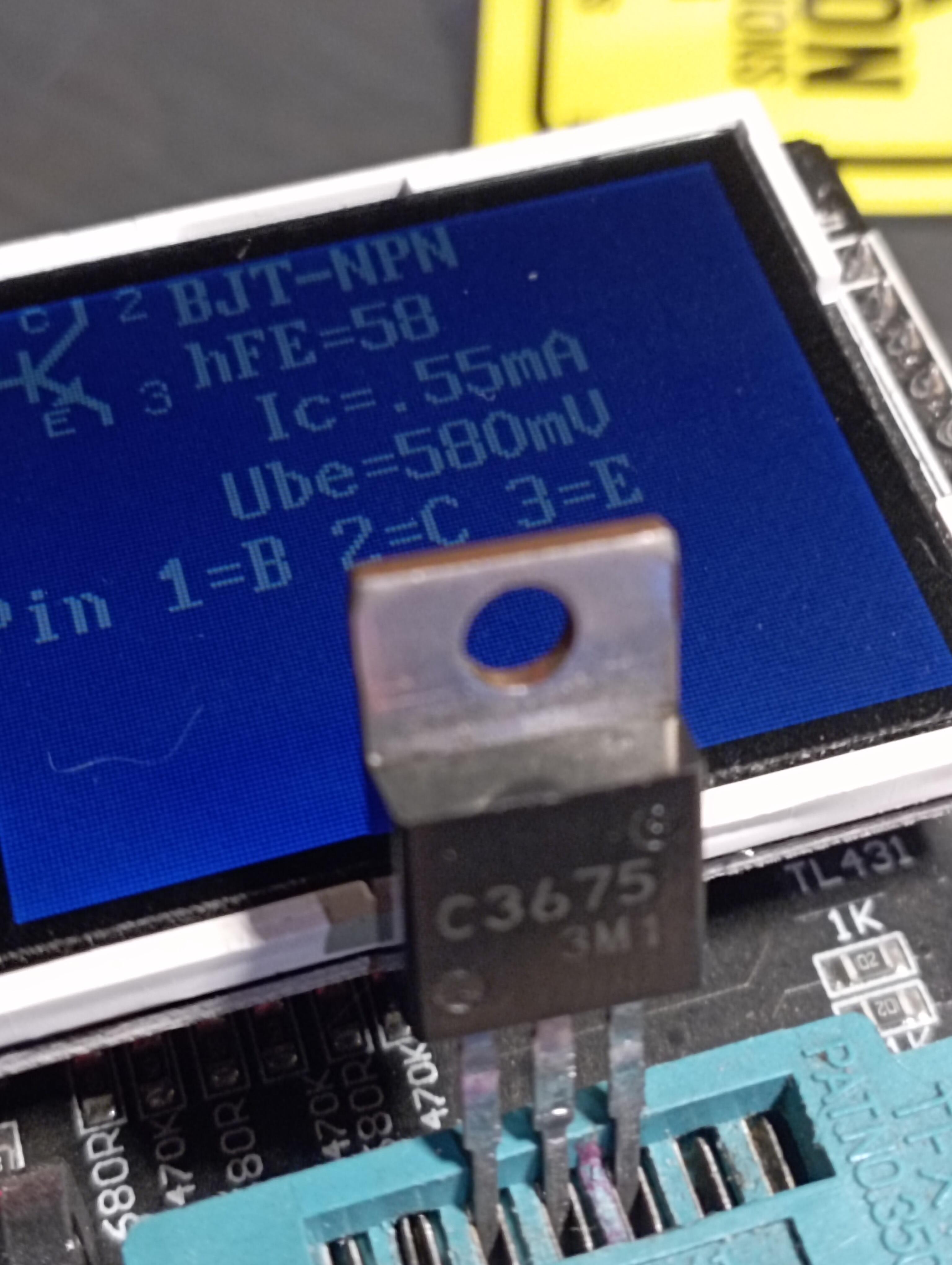
let's compare our devices when measuring 3675. I assume you have it.
-
-
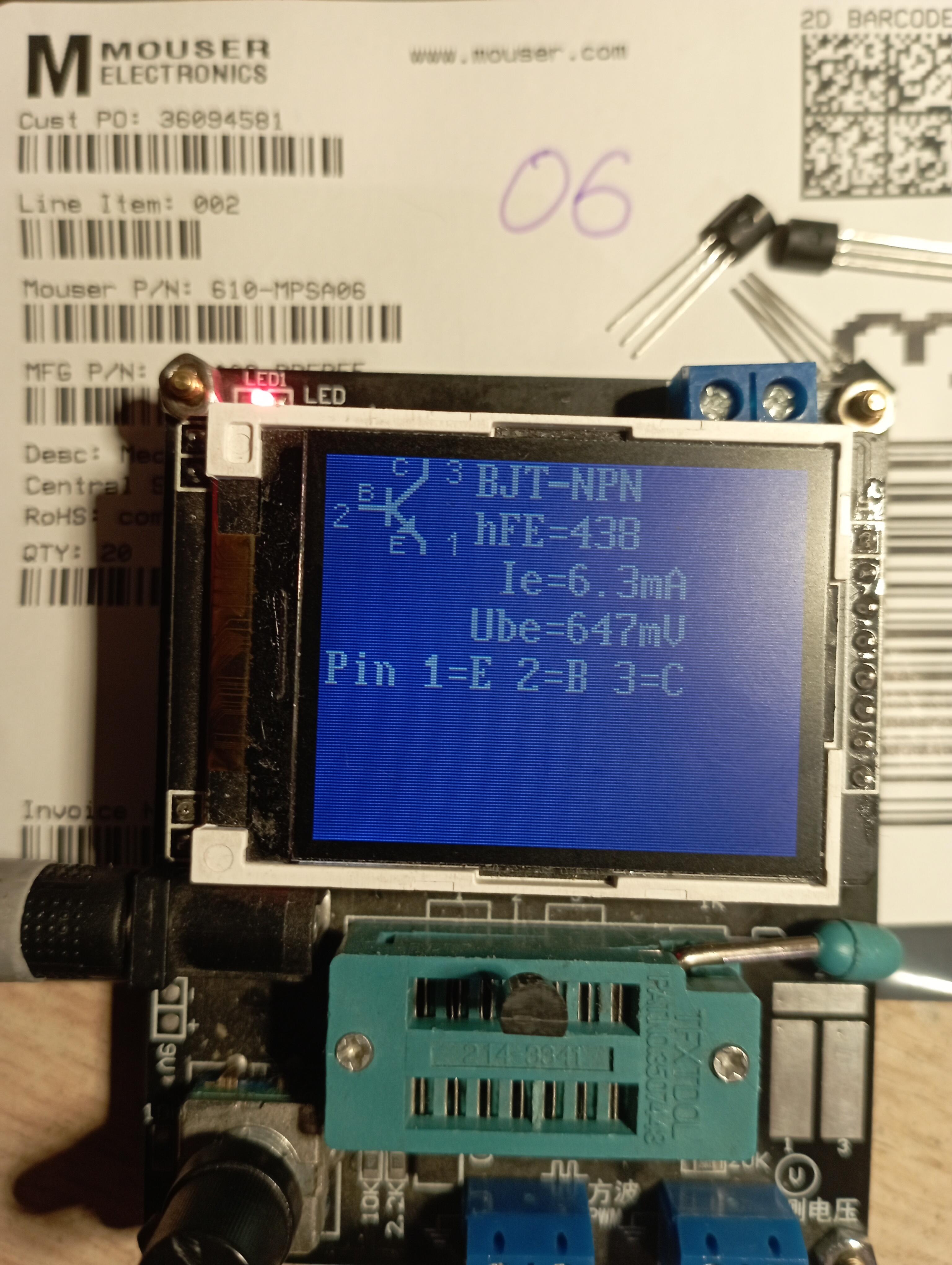
Earlier I asked about the adequacy of Mouser. We discussed the STN9360. Today I took the MPSA06 out of the package. I measured the hFE and again was surprised by hfe= 438. According to the datasheet hfe= 100. I had three PZTA06's and they show hfe=207. I will have to use c2240, they show hfe=241. I am shocked at hfe=438.....
-
sorry, I have one 100% original and 2 fakes, many do not know who the original is.
-
When I was looking for 2SA1968, I also got PNP. I couldn't make a claim to the seller, because according to the Toshiba datasheet, there is such a version too. Model 1968, one for the whole world, n-p-n and p-n-p
-
I'm not in the mass production business, so I'm not going to BUY expensive devices, meters, analyzers, for basic hFE determination. Over the last ten years, I've built many different versions of electrostat amplifiers. Yes, not all of them worked. Yes, I didn't like all of them. For example, the mini T2 really disappointed me. assembled version called carbon, I am happy for two years. But many music lovers always want something better. I hope that T2 will outplay Carbon.
-
In the batch that MOUSER sent me, the measurements were made at normal room temperature. One row of transistors had hFE 341, another - 315, the third - 295 and the fourth - 245. Which hFE would you use first?
-
when I bought in 2023 in Digi c2m1000170, they wrote that it was made in China. Now they don't have this model. I made a purchase on Aliexpress, alas, a fake arrived. I tried to make a purchase from another seller on Ali..., and to my surprise, transistors suitable for use arrived. I have already demonstrated photos of three purchases.
-
Please don't transfer your hobbies to me. I write only about radio components, that is, on topic. And you discuss about Gucci with women...
-
Yes, I'm interested to know why the increase is twice as painful, maybe it's better?