EL_Ken
-
Posts
14 -
Joined
-
Last visited
EL_Ken's Achievements
Member (2/6)
16
Reputation
-
and now for something completely different part 3
EL_Ken replied to kevin gilmore's topic in Do It Yourself
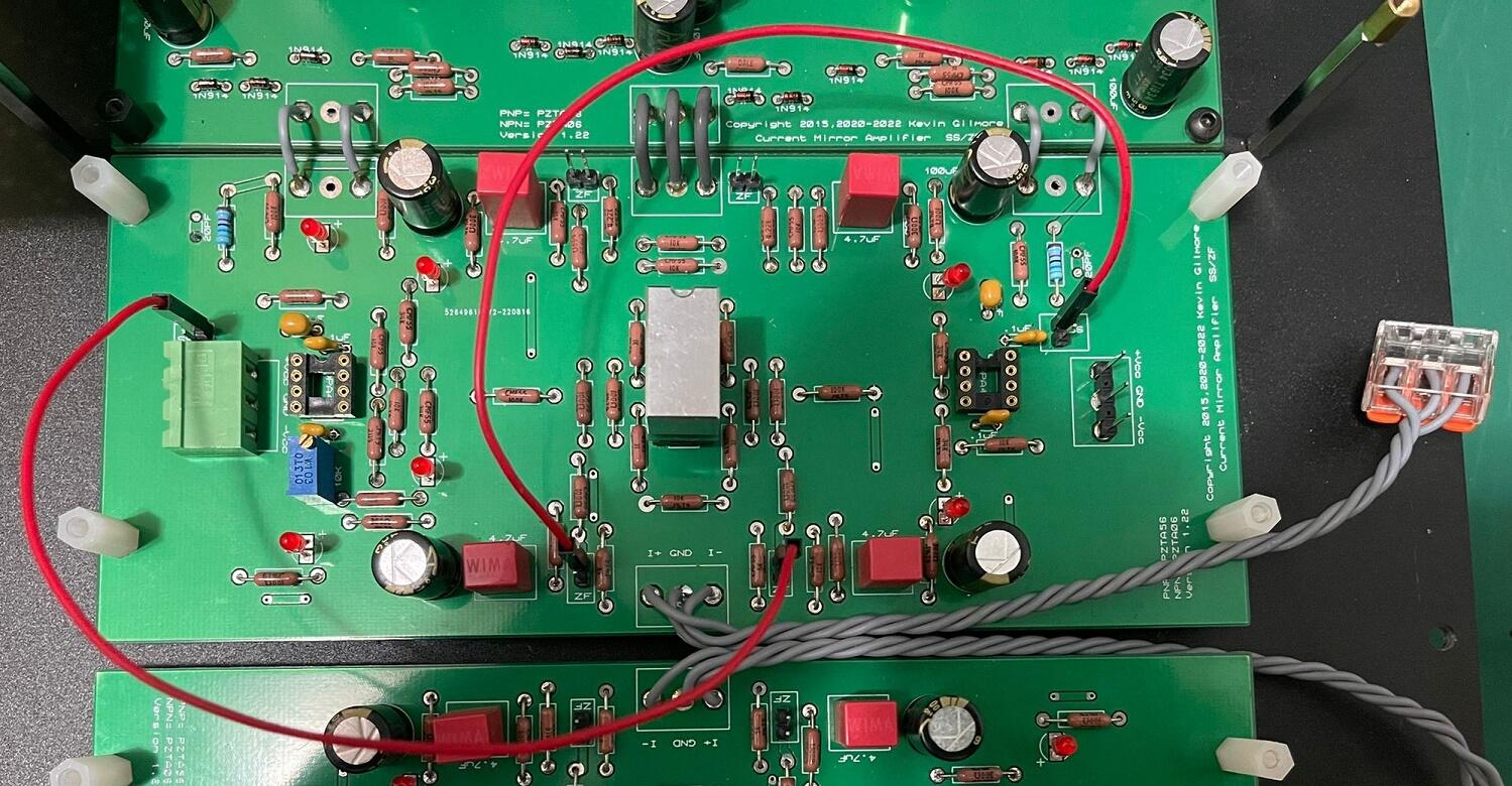
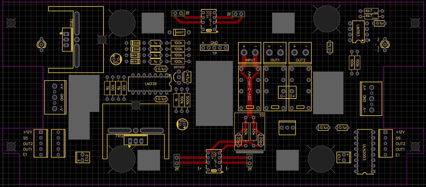
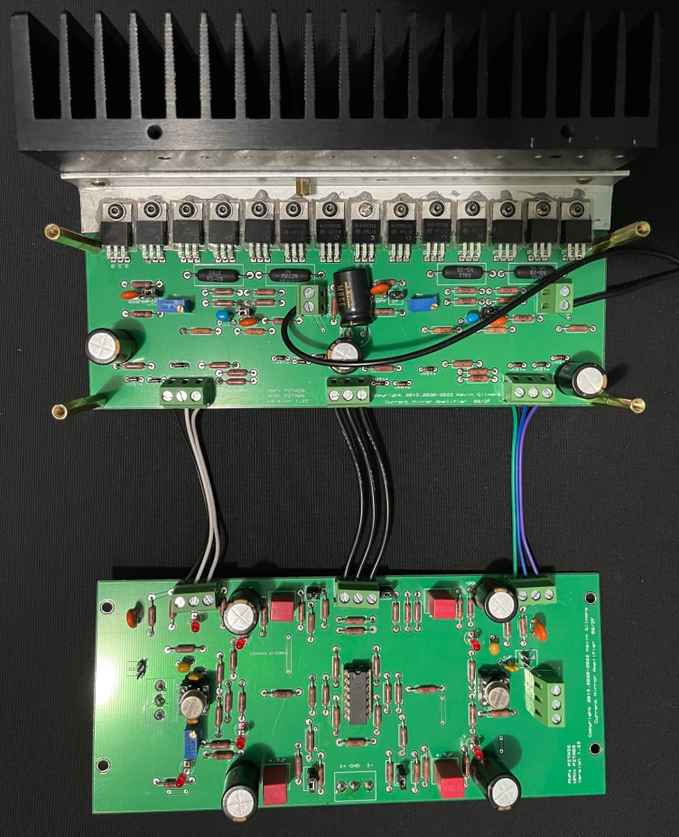
Reworking my CFA3 for ZF/SS switching. Inspired by ang728's hat board, I designed a split-board version. It works fine with ZF but has issues with SS: R channel: 0.2V offset, fluctuating ±0.1V. L channel: <30mV offset, fluctuating ±0.1V. Bias: Stable. Tried those solutions from previous posts but unsuccessful to solve any issues: -Removed hat board; use original jumpers for ZF/SS. -Added 680pF between B-C of output transistors. -Removed C9, C10 (20pF). -Replaced all PZTA56/06. -Swapped THAT340 / K389-J109 / K170-J74. Changing R171, R211, R272, R322 from 300R(silkscreen) to 600R(schematic) fixed the 0.2V offset, but both channels still fluctuate. Suspecting trace interference, I directly wired the jumpers to SS mode. The fluctuation is gone. So I redesign the hat board. SS resistors(R44, R49) sit on hat boards. SS jumpers and SS resistors are removed from cfp3smt2splitpre. My final result to get stable and low DC offet will be: -Using the hat board -R171, R211, R272, R322 = 600R. -Remove C3, C7, C9, C10 (600pF & 20pF) Thanks ang728, his posts helped me a lot.
-
and now for something completely different part 3
EL_Ken replied to kevin gilmore's topic in Do It Yourself
Will make new PCBs for RCA GND/circuit ground/(-) just as your words, thanks. I wire the +/- to the banana plugs, not using the circuit ground, same as 4pins XLR headphone out. R+L+ will cut off from unused output and R-L- remains connected. No issue with a balance source but not yet try SE source. There is no complete circuit when only (-)cable connected. Cut off all 4 channels for preventing noise from cable to amp? -
and now for something completely different part 3
EL_Ken replied to kevin gilmore's topic in Do It Yourself
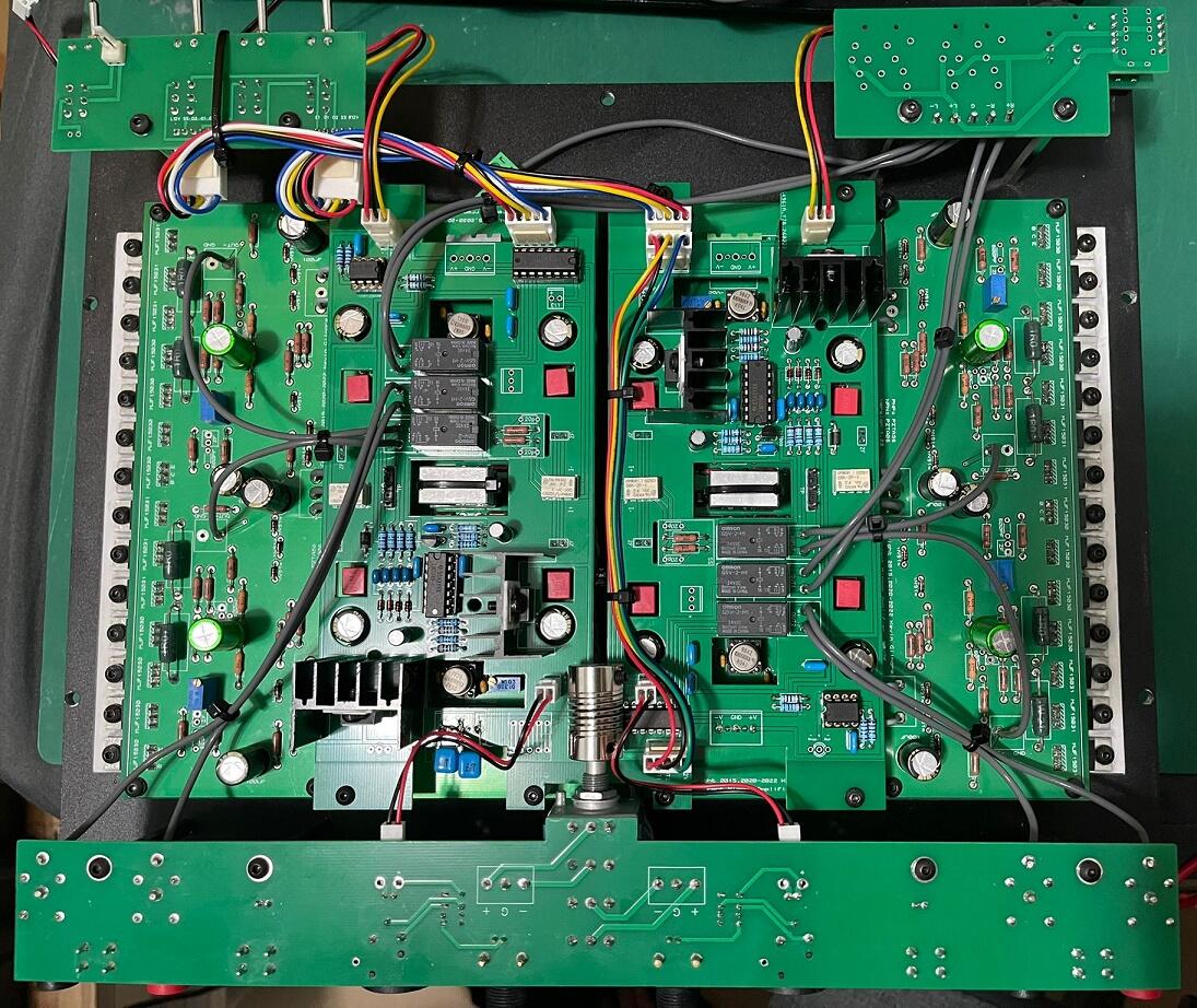
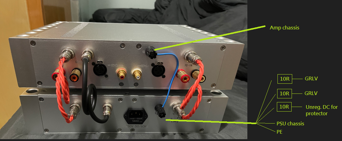
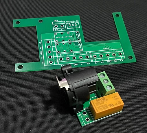
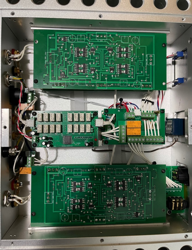
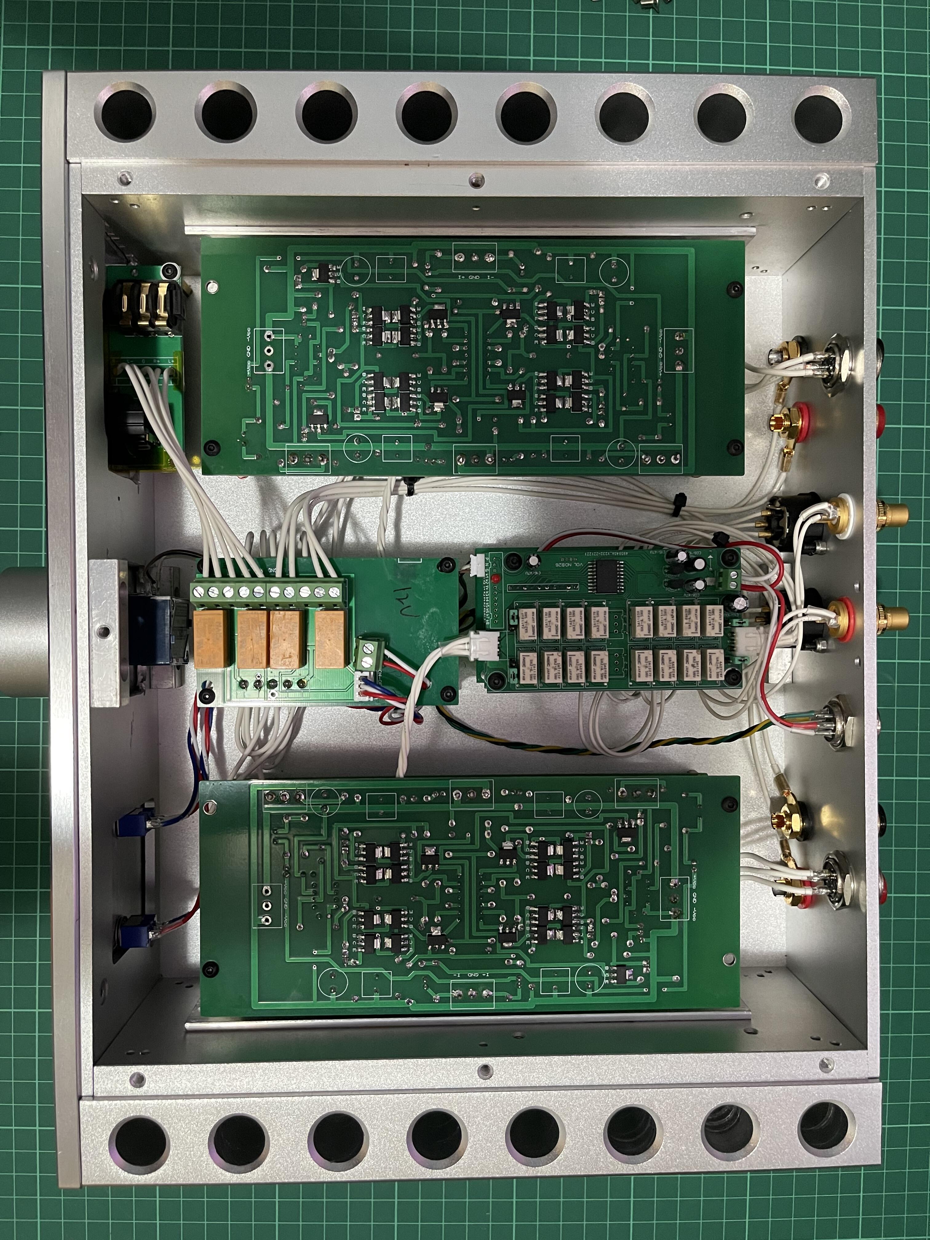
Thanks audiostar for crucial knowledge about grounding. Added banana jacks to both Amp & PSU chassis for grounding. When all cables are connected, circuit ground is measured ~3.5ohms to PE and every parts of the two chassis are 0ohm to PE. Next step is shielding the two DC cables to block out noise. Also made some PCBs for simplify wiring, reduce half of the cables. On the RCA/XLR board, XLR (1) & RCA GND connect to chassis through mounting screw of NC3FAAH2. Relay NC for HOT&COLD, NO for RCA (+) and short (-) to circuit ground. The larger board is used for switching headphone/speaker output. R- & L- are bypassed, only switching R+ & L+ between two outputs. Similar to Kevin's protector, cutoff R+ & L+ when DC occur. With those hollow areas, I can access the underneath protector much easier. Input transistors swapped to J109/K389 with 50K attenuator. Bias set to 150mv and temperature raises from 20°C to 45°C. Although this temp is ok for transistors but don't want being to hot as a desktop setup.
-
and now for something completely different part 3
EL_Ken replied to kevin gilmore's topic in Do It Yourself
That's some personal failure cause by reassemble the amp for many times. In my case, screws rub off the top insulation layer cause the problem. Multiple problems happened in same time made me confused so I posted for asking help. Hopes nobody repeat the same mistakes. Fixing the problems I made, will report here soon. -
and now for something completely different part 3
EL_Ken replied to kevin gilmore's topic in Do It Yourself
Thanks for you help. Not yet powered my amp, will get some 10R and finish the grounding first. -
and now for something completely different part 3
EL_Ken replied to kevin gilmore's topic in Do It Yourself
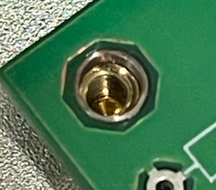
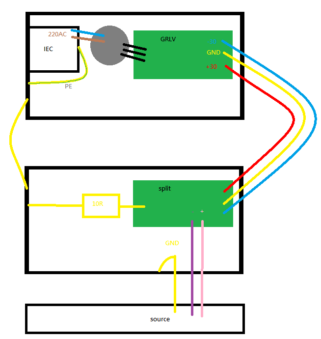
Had done isolations between sands and heatsinks. And then finish casing the PSUs (PE connected to case). When I powerup GRLV alone, DC voltage goes wrong and pass transistors dead. After checkings, I find GND on one of the GRLV shorted to case. Top green insulation layer of pcb (near mounting hole)is damaged. This short GND and case through screw. So I thought that's the reason the transistors dead. Maybe the transistors were damaged by desoldering, had to resolder them to fit the case. But none of the circuit connected to PE will cause risk of electric shock. And proper grounding can block out noise. And I found some of your words said before. Hope my drawing below is understandable. GND: Splitboards > 10R resistor > amp case > extra wiring to PSU case > PE
-
and now for something completely different part 3
EL_Ken replied to kevin gilmore's topic in Do It Yourself
English isn't my native language. Hope I didn't misunderstand your words. That's mean don't connect circuit ground to PE, right? PLT-163 connectors used for DC in/out. 3pins are +30V / circuit ground / -30V respectively, none of them connected to case. I had once mis-connected circuit ground of GRLV to chassis, and killed the pass transistors. So, I think circuit ground should not be connected to PE/chassis. Now the whole system is floated from PE/chassis. None of the circuit are connected to PE or chassis. Sorry for my ignorance and please correct me if something wrong. -
and now for something completely different part 3
EL_Ken replied to kevin gilmore's topic in Do It Yourself
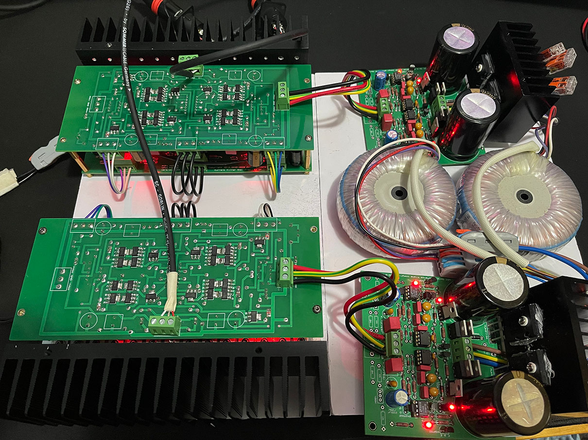
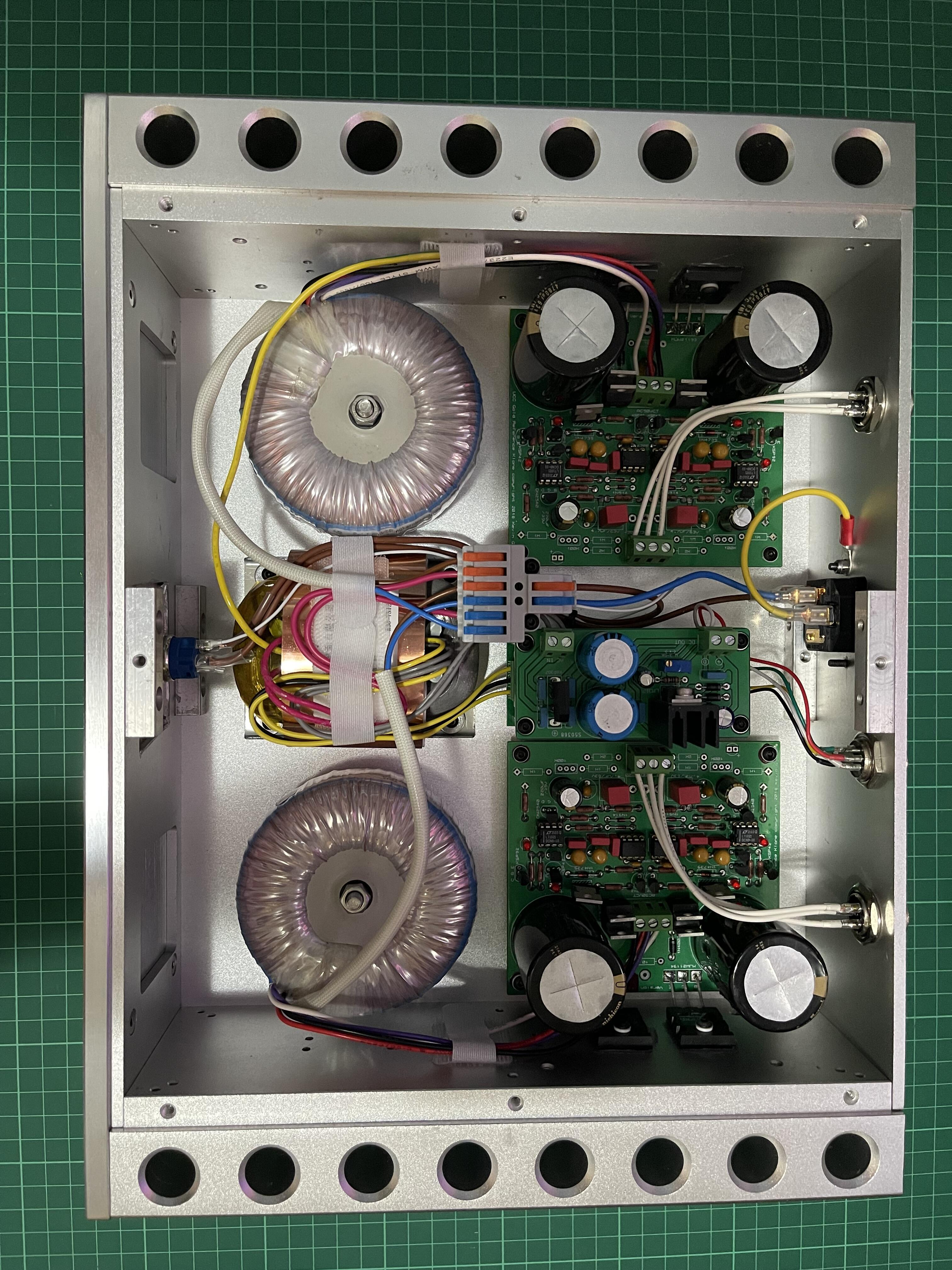
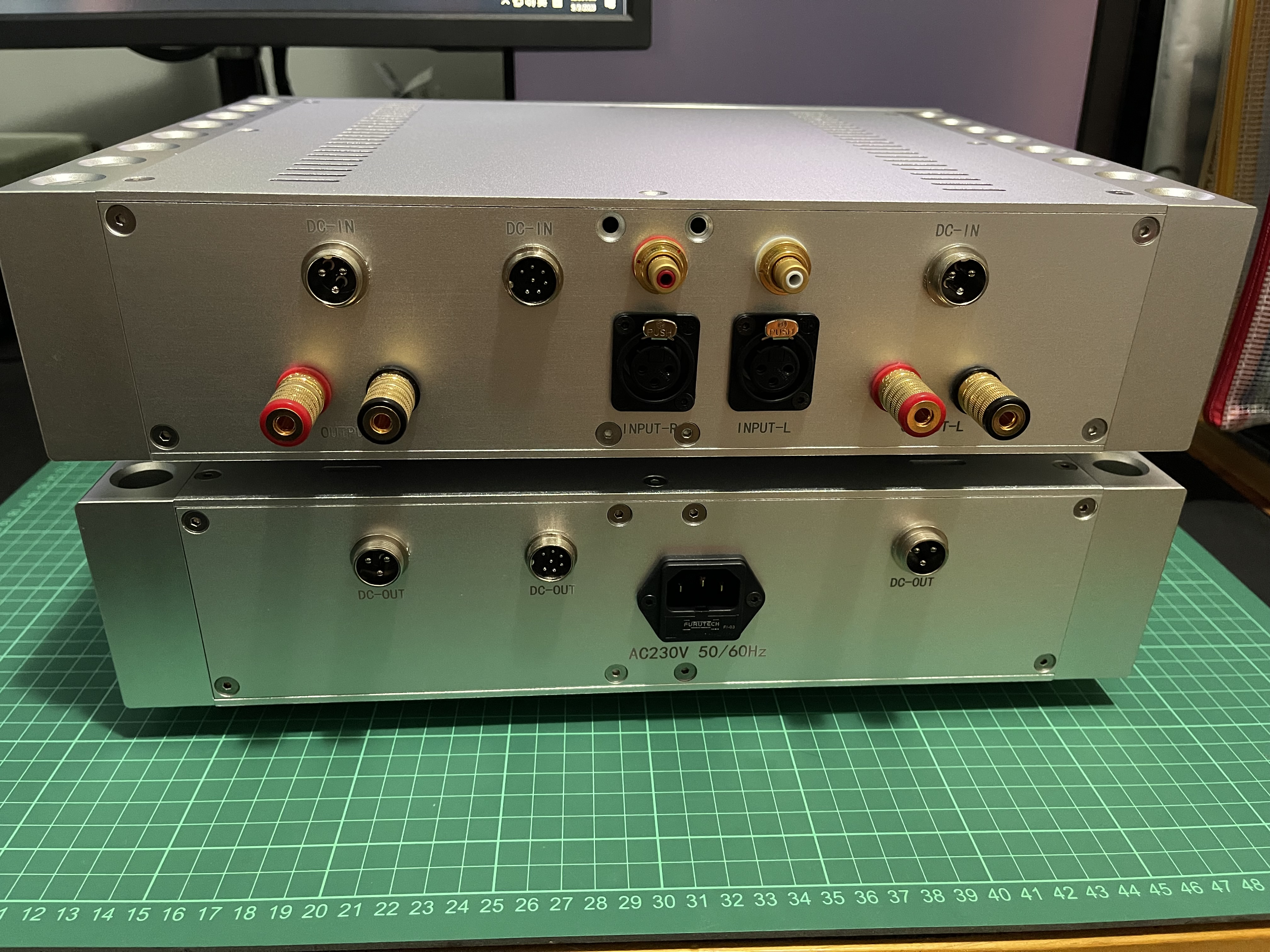
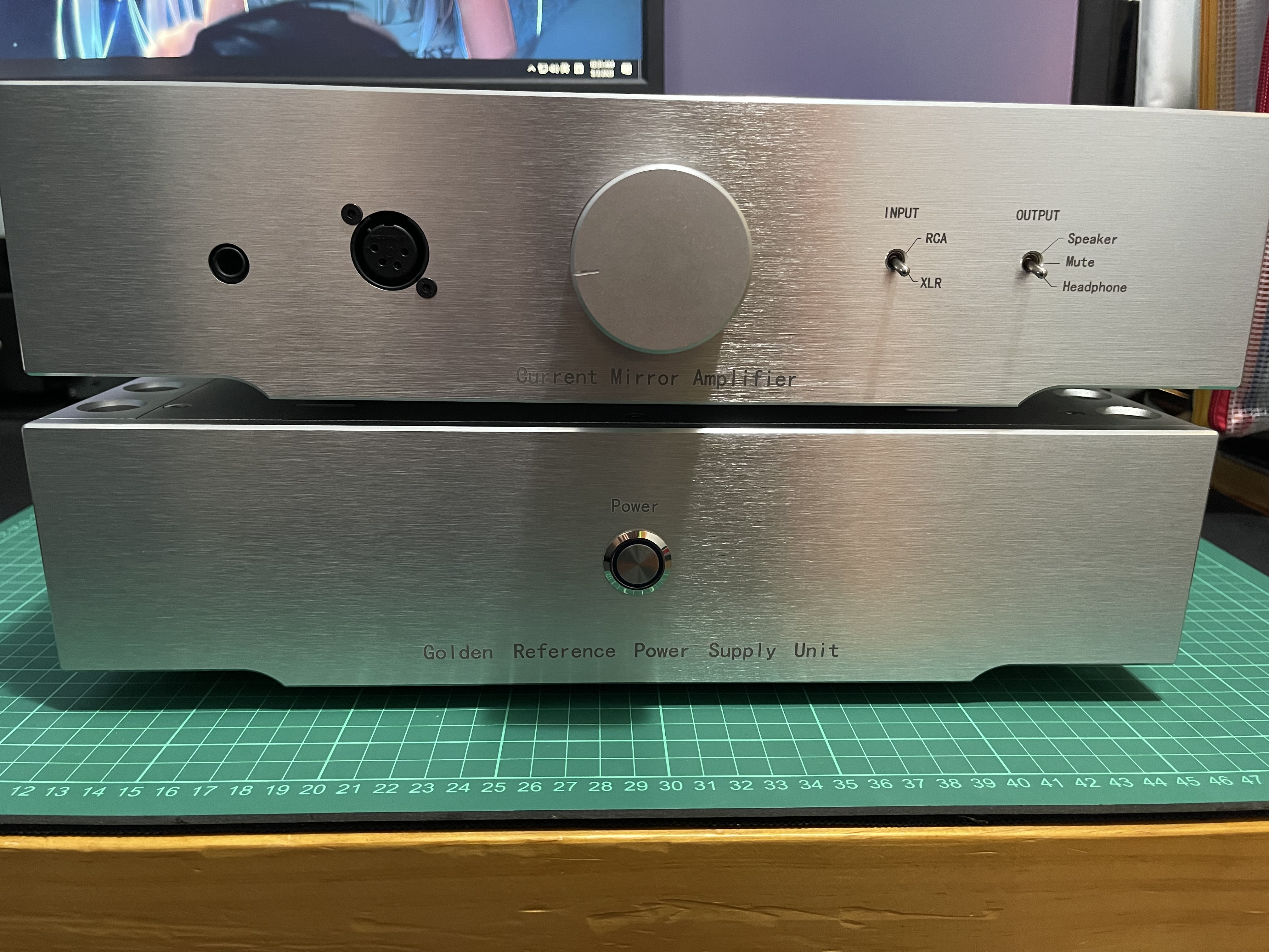
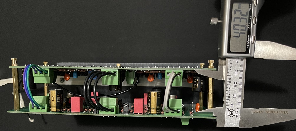
Just finished casing. Case size 360*270*86mm (inner 280*255*73mm) Dual GRLV ±30V Extra DC supply for attenuator, relay boards and Protector. Ship-in-bottle-like building experience with small cases and multi layer PCBs. Some very soft cables would make it easier. Difficult to adjust those trimpots on splitboards after casing. Better to do the adjustment before casing. Spider webs at the input state is a mess. Better-designed PCBs can reduce half of the cables. Will fix that after I get a new back plate and PCBs.
-
and now for something completely different part 3
EL_Ken replied to kevin gilmore's topic in Do It Yourself
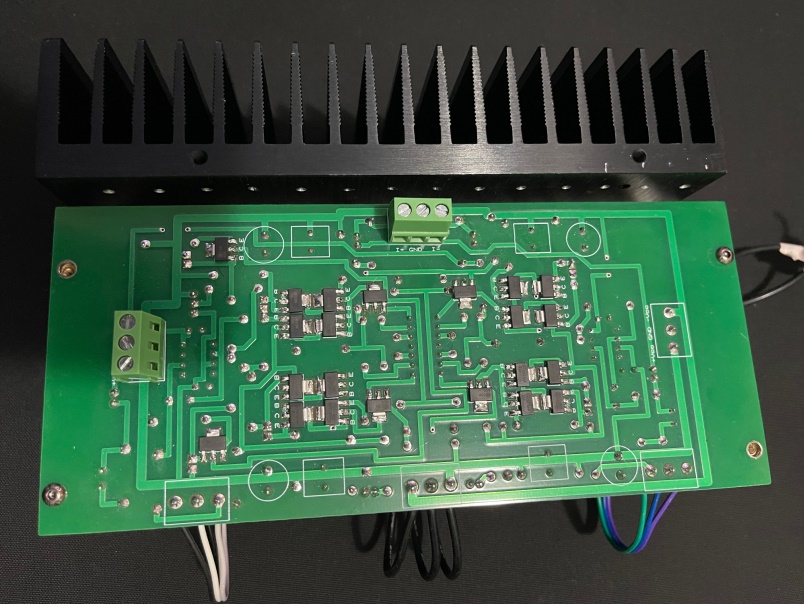
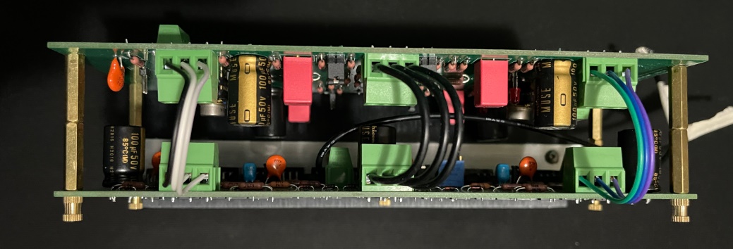
Output transistors are MJE15032G/15033G, extra insulation is needed. Size of the heatsink is 200x62x40mm, ~50°C with 120ma bias. It could handle more heat but I need larger heatsink for GRLV. The nichicon kz cap (Ø:12mm) is too big so one has to lying down. Edit: one more pic added
-
and now for something completely different part 3
EL_Ken replied to kevin gilmore's topic in Do It Yourself
All GND pins and pin1 of XLR cables are shorted to each others. Screened cables - POT - silicone wire Some silicone wire from local store, no much interference issues. Only a bit white noise from headphones when pot turns over 3 o'clock.
-
and now for something completely different part 3
EL_Ken replied to kevin gilmore's topic in Do It Yourself
Sorry for making every one confuses, After rewiring the pot, problems gone. It causes by incorrect grounding. A 10k pot can adjust volume from no to full with proper wiring. Now using that340, will try swapping input transistors later. Had music continuously with DAC-preamp-splitboards for 10+hours with no problems, Testing with DAC-10kpot-splitboards setup, works fine too. Thanks for the help. -
and now for something completely different part 3
EL_Ken replied to kevin gilmore's topic in Do It Yourself
Just finish soldering my split boards. There are some problems happened dual to my bad SMDs solder technique. IF non-wetting happens / flux not clean-up between pins, no bias from 1R resistors and all output transistors not heating up; and very high DC offset can be measured from output to GND (~10-27VDC). I resoldered all the SMDs to fix this. After that I powerup my spirtboards, an 1R resistor heats up quickly and smoke comes out. One of the output transistors(Q17) shorted, replace it and no smoke again. Finally I test the split boards with a pair of speakers and HD600, both speakers and headphone sounds very well. But when I test the boards with my DAC and preamp which have ~100ohms and ~1ohms output impedance respectively, a 10k pot can only adjust volume a bit , only a little volume change from 10kohms to 0ohm; sound still comes out at 10kohms. A 50k pot could fit but some previous works in this post use 10k pot. Did I got some mistake with my work? Edit: A 10k pot can adjust volume from no to full with proper wiring.
-
and now for something completely different part 3
EL_Ken replied to kevin gilmore's topic in Do It Yourself
Thanks for your reply There are 4.22k0.5% & 6.98k0.1% resisters in my hands. In worst cases, will be 4.24k&6.97k but still within the 1% range. So I will use them. I've already picked up some 1/2W 50ppm 0.1% resisters and keeping the same spec for rest of the resisters. I think this is probably an overkill. Costly but no regret and happy to have this lesson. -
and now for something completely different part 3
EL_Ken replied to kevin gilmore's topic in Do It Yourself
I am building a pair of split boards(cfp3smt2splitpre&cfp3smt2splitamp) It is difficult to find 4.2kOhms&7kOhms resisters while I’m planning to use Vishay/Dale CMF55 series. And there are only a few choices from Mouser (4.2k:66-RC55LF-D-4.2K / 7k:71-PTF567K0000BYEK) Should I stay the exact value or use 4.22k&6.98k instead. Thanks


.jpg.6ab970eeea4ec76ce89349675607823e.jpg)