
Mullet
Returning Member
-
Joined
-
Last visited
Everything posted by Mullet
-
Ok... I think I figured it out. I used Belden cable for my hookup wiring and it looks like ground and left channel were touching because a dodgy stripping job. So chalk it up to faulty cabling. Phew!
-
I initially noticed issue when both channels were out of balance. I first looked at the hp jack because I noticed it wasn't isolated from chassis ground. I've since fixed that issue. Then the sound got better. Both channels balanced with same apparent level, but with the lack of bass and what seems like a really wide stereo image. Wider than expected. It could be a phase issue. Would a grounding issue show up as phase problems? What's interesting is that it's only in the bass region. Connectivity looks correct. I've toned everything out with a DMM. So I don't think I have anything backwards. IN1 is my left channel and IN2 is my right channel. Same goes for outputs. Other things to note: I did have signal ground connected to the chassis then through a ground loop breaker. I haven't been getting hum so I've removed the GLB. Same issue. Using the GLB, It made the chassis share the same ground as signal ground. Not sure I'd want this... maybe I do? I also originally only had OUT1, OUT2, and one of the GND paths going to my HP jack. I've since added the the 2nd GND path. No dice. Sounds the same. I did buy 2N5564 on eBay. I know I prolly shouldn't have. Could poorly spec'd or fake 2N5564 create a situation where the bass is so rolled off? FInally, trying different headphones didn't make much of a difference. I mean they sound different, but don't have bass. I'm going to try a full rewire on the outputs to see if that makes a difference, but may look at replacing the 2N5564 next.
-
I recently finished my Krell KSA-5 Klone. I'm having something weird that I can't quite wrap my head around. When listening to music there is a lack of bass. It just seems to be sucked out. I swap the same HD800S headphones into another amp and voila bass is there on any given track. I don't hear any distortion or a buzz or anything that would be akin to a ground loop. Anyone ever heard of this kind of phenomenon with this amp?
-
Do you mean that the voltage across the test points will constantly change? In my case I set the voltage to 125mV via pot after the amp has been warmed up. It drifts a little but doesn't stay exactly at 125mV. Or do you mean the dc offset with OPA445 removed? This is who I bought 2n5564 from... https://www.ebay.com/itm/1PCS-New-2N5564-CAN-6-Matched-N-Channel-JFET-Pairs/392370230460?hash=item5b5b1694bc:g:wDEAAOSwvFNdSPV7
-
I'm no expert, but I'd just use the suggested parts. You're thinking of using these instead of LSK389 or 2N5564? I know this is generally not advised, but I got the 2N5564 on eBay from seller Top Chips. I've recently fully powered up and tested the amp prior to casing things up and the amp plays music. So the parts are legit? I have no way of telling. My guess is the amp wouldn't work at all if the parts were fake. On another note, you do have to watch out with eBay - I tried to skimp on paying $12 x4 for the OPA445 and bought them on eBay. When trying them out in the PSU no voltage or close to none. I ended up having to go to Mouser with my tail between my legs and bought 'em there. Boom success!
-
-
Quick question when matching transistors... on same channel - L or R... do you match PNP to NPN with similar or same HFE? or do you match NPN to NPN or PNP to PNP?
-
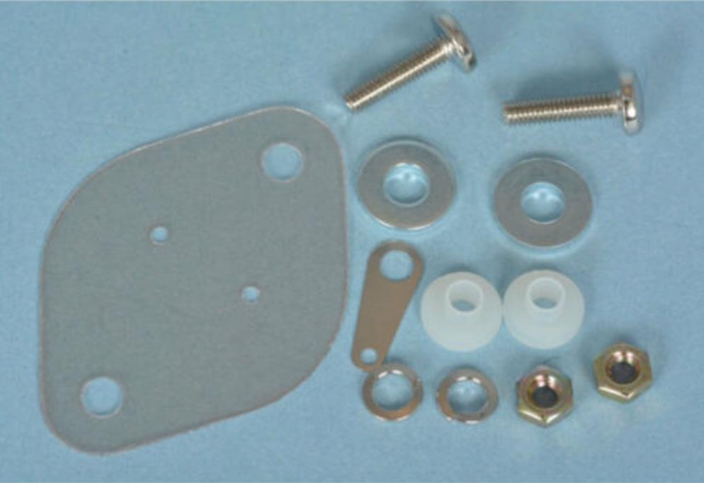
For the alternate power supply shown a few posts above, what hardware is requiered for the TO-3 transistors? I'm looking at kits on eBay and they come with more parts than I think I'd need. I'm thinking all that is needed is: 2x plastic washers, 2x screws, and 2x nuts. The kits come with 2 sets of metal washers and a metal tab for soldering. I'm thinking I wouldn't need these extra parts. See attached picture.
-
So I ended up figuring out what my hum issue was after moving trafo orientation. BTW this is for an EHHA Rev A. It turns out that my RK27 was going bad. After readjusting everything, I noticed that I was still getting leakage even though my pot was fully turned down. I could hear a small amount of audio coming through. I replaced the pot and now we're back in business. With regard to my Klone, are those silicone / mica insulator kits for all the F15030/1 parts required? I'm counting 10 on the main amp board and possibly 2 on the alt. psu board.
-
Interesting. So basically turn the transformer until it's facing a different direction and thus reducing the hum. In this case it seems there is a possibility of having to permanently extend wires to get enough length.
-
Not on this particular amp. But I do have it on another amp and I was thinking of taking precautionary measures on this one. I'm thinking of going single chassis.
-
Thanks! Anyone have experience with these iron transformer covers from eBay? Do they really work? I'm thinking of using one in my Klone. https://www.ebay.com/itm/1pcs-toroidal-transformer-circular-cover-the-105-51mm-balck-metal-Metal/264373072892
-
I'm finally about to build my KSA-5 Klone. I shelved the boards for like 5 years - can't believe I waited that long. Thus far with eBay and a cart full of goodies from Mouser I've gotten the price down to a reasonable ≈$215 including I/O jacks, standoffs, etc. The kits offered on eBay are cheaper. I've been tempted to buy the kits, but fear the parts are cheap and cheerful. After reading through most of the thread... a question or two... For the 2Ω resistors - can I use this? - 667-ERX-3SJ2R0 Or are 1% resistors necessary throughout amp? Thx, Mullet
-
Just figured I'd spread the good word... http://tinyurl.com/luoq6cj If you know of any vendors that might be interested or you are a vendor that is interested in participating please PM me.
-
Nope no ferrites. I have tried installing them to no avail. So I put the jumpers back in place. So basically only thing that doesn't check out is the "no reading" on pins 1 to 3 on U3. I'll try re-flowing those joints. So are you saying that 1 to 3 should be slightly higher than 8 to 3? Does U1 look right? Here are some pics for posterity...
-
Most current readings: PSU voltage unloaded is 24.16v coming from a 24v Jameco linear regulated supply. 23.33v between pins 4 and 8 on U3. 11.64v between 3 and 8 on U3. Nothing between 1 and 3 on U3. 11.5v between 3 and 8 on U1. 23.36v between 4 and 8 on U1. 9.92v between 1 and 3 on U1. Red lead on MM is going to pin 8. Red lead is going to pin 1 as well. Thanks for the help guys. Pictures to come.
-
Got it. Do not pass go.. and go straight to the minified PINT.
-
I want to tackle and finally finish this PINT amp I recently acquired. It's old school and I scored the board for next to nothing, so what the heck. I know the project ended up ceasing because of the crankiness of the 8397. There’s got to be a way to tame this thing. At this point, I’m not sure if I’ve fried the opamps, but I can say that the 8397 gets very very hot. I’m using the LM6172 as my GND channel opamp and this is getting quite warm as well. This is when I power the amp with at least 18v or 24v. I'm getting an unusual amount of DC Offset -- basically the rail supply for each reading that I've done. At first the amp seemed to work but music sounded hollow and not quite right. So I decided to reflow some of the resistors, particularly on the left output side. This is when the problems started. I swapped out both 8397s that I had on hand and both have issues. I’ve removed the LM6172 and put an 8397 in its place. Currently, it’s back to one of the 8397s and the 6172 in the U3 position. I started the build with these values… R2 - 100k R3 - 120k R4 - 240k …for a gain of 3, which should be fine for the AD8397. Then I switched to the default values of... R2 100k R3 - 120k R4 - 620k …to see if that would help things out by balancing the input bias current. No dice. Here are some readings with a 9v battery to prevent the opamps from getting too hot: DC Offset IG to OG 3.93v IG to R -3.83v IG to L 3.83v U1 IG to Pin 1 2.88v IG to Pin 2 .426v IG to Pin 4 -3.81v IG to Pin 6 .551 IG to Pin 7 3.74v IG to Pin 8 3.74v U3 IG to Pin 4 -3.78v IG to Pin 6 -3.77v IG to Pin 7 -3.77v IG to Pin 8 3.72 So it looks like I’ll order a few more 8397s and maybe another 6172. I recently bought an oscilloscope, but have yet to learn how to use it. I figure this would be the perfect opportunity to see what oscillations look like. Perhaps I’ll even figure out what ferrite smds are needed, if any at all. Any ideas? Don’t want to give up. I could pull a bunch more parts out and do the alt. version without C1.
-
Don't know if anyone has an extra set of boards -- Amp and PSU -- but if you do please PM me. This looks like a fun project.
-
I'm looking for a KSA-5 board/PSU board as well if anyone wants to give theirs up.
-
I'm using an Early 2009 Mac Mini with my Samsung HDTV. It works great! At the moment, I'm using Boxee as my media player and EyeTV as a DVR. I also set up a IRTrans IR blaster using iRed2 to change channels and do some home automation like dimming lights, etc. I use my iPhone to control it all. This is my first foray into Macs and everything is working out great. Super easy to set up and no fuss no muss.
-
I'm looking a few different options. I'm looking for a [redacted] that let's the [redacted] do the heavy lifting and retain its signature sound. So I guess the [redacted] has to be clean and [redacted]. I'm looking at the [redacted], [redacted], [redacted] and also the [redacted]. What are your thoughts on my selection?