eslover
Members
-
Joined
-
Last visited
Everything posted by eslover
-
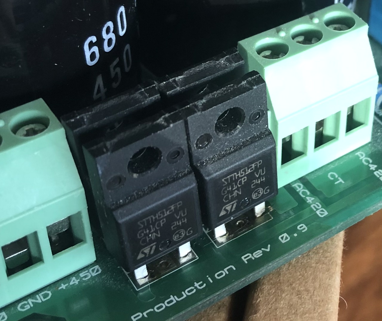
It took me 7 years to build my second kgsshv, or so I thought, and no cigar as I powered this one up. I have a problem with the positive, HV rail in the power supply: I measured ~10V instead of +450V. I need some help to troubleshoot. Couple of things: 1) when powering on, after long discharge time, I get sparks in the neighborhood of the 680uF/450V caps for that rail. This lasts for a second, and goes away. First time i switched off right away, but when I turned amp back on soon after, no problem... if one waits more than 30minutes, then small sparks come back on first “ignition”. No smoke. 1b) After close visual inspection, two legs of the bridge diode for this side of the PS are a bit darker than the others (bronze close to pcb rather than silver). These are the legs connected to the top plane of the pcb. Using a multimeter, diodes seem to be ok for allowing current flow in one direction and not the other (using diode checker on multimeter). There seemed to be missing copper pads top of board (if there was any). Above the 0 in the rev0.9. 1c) I confirmed the two legs, one per diode, are not connected to top plane. Did I vaporize copper at first power up, or was there even any (I assembled the ps years ago, never checked before assembly as I solder from bottom face) 2) output of transformer measures 493V AC. (Both sides) 3) negative rail of PS OK (-453V out of PS). 4) PS board is regular size (not mini), rev v0.9. Any help would be greatly appreciated. Thanks.

-
I bought a v1, knowing full well it was a first release. Anyone who knows anything about product development- and that should apply to diyers - would know that perfection from the get go is not a realistic expectation. Soekris released the board to great expectations, and to his credit (and benefit) listened to the community that helped improve the product quickly. Though Soren went the commercial route, he also preserved the diy line. To me, this sounds like a win-win, and helps the industry. Soekris "crowdsourced" some of his dev costs, and anyone, including competitors, can read diyaudio and some of the lessons-learned (in particular re. Filter design). for v1, you can get a daughter board from nordmundss that takes the performance higher (buffers), and resolve the shutdown "plop" . Finally, a couple of smd caps for the shift registers was less than $2. Ability to solder such tiny things, priceless!
-
Nice RudeWolf. Not evererybody reported loud plops when changing Fs with the amanero (see dimdim post and video). I am wondering if it has to do with the drivers (?). I guess i'll find out as son as I get the amanero.
-
Ok, maybe not QC at end of production line, but they - stax, the importers and the retailers - should either package the earphones well enough so it does not happen or design the product so it can withstand the treatment from the shipping companies. When you buy eggs at the supermarket, you expect them to be fresh and without cracks!
-
Now, if it makes you feel better, my 307s also had a significant channel imbalance. What's up with Stax quality control?
-
Music! I still have plenty of work to on the casework before i can post pictures, but right now is a happy moment. Thank you Kevin for the design and the tips, lil knight and eggil for the boards, picaudio for some neat connectors, and the head-case community in general for the sharing your knowledge. P.S: I replaced the 2k series resistor for the offset pot with 1.2k. Offest and balance on the outputs drift below +/-1V, close enough.
-
I am red faced... I went to Radio Shack first thing in the morning to get LEDs, got home, heated up the iron to desolder the LED, only to realize that one of the LED legs was not soldered. How could I miss that?!? I put a bit of solder, turn on the amp and voila, all is well. Thank you for your guidance, now comes the fun of zeroing the outputs. Btw, for my voltage settings, the offset resistors are at the lowest setting so I may try a 1k in series with the pot.
-
Changed the 1815. Same symptoms. I don't have spare LEDs other than white. Would the voltage drop be too big while i wait for red to come in?
-
Not much... -240mV and -175mV. So what do I change? The C1815? The OK board shows ~10V at the top of the diodes.
-
The outputs of problem board are unresponsive to offset or balance adjustments. Both are stuck at vcc. The LED that does not light up is the bottom right one on the picture. The LED in the middle will come off with high balance setting. Could it be the LSK389 that is faulty or fried? I adjusted the other board's outputs to 0v
-
Thank you Kevin. Though that may have to wait until next week-end, I will try and report.
-
I finished cabling the onboard version of the kgsshv (v0.2). I am running in some trouble with the amp boards and could use some help and pointers on how to resolve the problem(s) - Power supply is OK +/- 445V (I was going for ~450V), and +/-15.0V. - On the first amplifier board, one LED does not come on. That's the LED that is closest to the lsk379, towards the lower left corner of the board. The voltages at O+ and O- are the same as for +VCC (+443V). -VCC is -442V - On the other amp board, all LEDs are on. O+ and O- are approximately 20V apart, (+110 and +130V). +VCC and -VCC read the expected values (about +443 and -442V). All voltage measurement with respect to ground. All measurements with Khozmo attenuator set to lowest level. All transistors from respectable sources. Any help to jumpstart the troubleshooting would be appreciated. Thanks.
-
Wire leads. For each step, the measured resistances where within +-1.5% of each other.
-
I received my Khozmo attenuator last week. It's the smd version, and it operates much smoother than I had anticipated or the Dact I previously owned. I measured all 48 steps with no surprises. FYI: It took exactly three weeks between the time I paid for the device and when it showed up in my mailbox.
-
Thanks for the clarification Kevin, that's helpful. As you did not seem too concerned, I'll go for a wood case.
-
Hi Kevin: I am scratching my head for the casework. On a much earlier post in this thread, you recommended to ground of boards to the case. But what if the case is not made of a conductive material? What do I need to ground exactly. I never worried in the past, but nothing I ever built run with more than 35V rails. In addition, I originally intended to use wood for the case like in the previous amps I built (no HV) as it is much easier and pleasant for me to build. Reading stories of sparks flying by a few builder, I am having second thoughts. Would you advise against wood? Or a plastic case?
-
FYI for those who may still be looking, bdent just received some 2sa1486. No idea how many are in store, or if they are real, but some are coming my way. These little bastards have been hard to get at a reasonable price.
-
I'm in. It may be faster this way too.