


JimL
-
Posts
641 -
Joined
-
Last visited
Content Type
Profiles
Forums
Events
Posts posted by JimL
-
-
It's a totally differential circuit, so a single ended input automatically gets converted to a balance output - you are using both sides of the output regardless, so that wouldn't work.
-
20 hours ago, Blueman2 said:
I changed my Carbon to 20ma (from 17ma) and at low levels, could not really tell much difference. However, when I cranked up the volume, it made a huge difference. Much brighter and more shiny. In a good way, for my ears. I know it is cliche to say you can hear things you did not notice as much before, but in this case it is just true. I keep getting surprised by sounds I had not heard before coming from my old standby albums. I am dedicating all day tomorrow to just listening to the Carbon. I have no real desire to finish the chassis now; I just want to listen to it.
How fickle audiophiles are!
 Just a week ago the SRX Plus was the greatest thing since sliced bread, and now...a new girl and the old one forgotten.
-
Looks a lot like the front end of an electrostatic headphone amp (T8000-ish), but with relatively low voltage transistors (except for the KSA1156). You could always substitute a MOSFET current source for the input tube tail CCS.

-
 1
1
-
-
On 11/11/2017 at 12:22 PM, Blueman2 said:
Question about filament voltages. I have seen numerous recommendations to slightly reduce filament voltage using an in-line 10W resistor of 0.5 Ohms or so. Looking at my Antek transformer, its filament windings are rated at 6.3VAC at 115VAC input. Here in SFO Bay Area, I average about 125VAC on my lines. This gives me about 6.8V on the filaments, so almost 10% high. I am not too concerned about lifespan of the tubes, so long as I get around 1000-2000 hours out of the output tubes (6SN7 in my case). Is it recommended I add a voltage reducer? For a pair of 6SN7s, would about 1 ohm be too much? I am not worried about the input tubes (12AT7s) as much (or should I be?).
So, it was shown decades ago that 5-10% high filament voltages will decrease tube life. On the other hand, running your filaments 5=10% low will not affect cathode emissions much. 6SN7 tubes draw 0.6 amps each, or 1.2 amps for a pair, so an 0.5 ohm resistor will drop your filament voltage to about 6.2 volts, while a 1 ohm resistor will drop it to 5.6 volts. Somewhere around 0.7-0.8 ohms should do it - a wire wound resistor of those values is pretty inexpensive.
-
6 hours ago, Monya said:
I’m no electronics bod and have no idea if the circuitry is new, old or whatever but experience has taught me that advances don’t necessarily translate into sonic improvements. To me this amp is very musical and makes for long term easy listening which is what I’m after.
If I were living in the States I’d have the BHSE but over here in the UK living within 10 miles of the factory should something go tits up I’m more than happy. I don’t want to be shipping hardware across the pond or Iceland!
5 hours ago, Forza AudioWorks said:Hardly any surprise there with tuning, all Trilogy stuff sounds quite similar; gutsy and authoritative. These machines are not about speed, clarity and resolution in the first place, but substance and thickness instead. As you've put it, musicality is the focus usually. Their 933 HP amp (Class A packed into CNC milled aluminium enclosure) does the same things. My two cents.
So the major issue I have with the Trilogy is this: given the tube complement, the only possible circuit is the Egmont topology shown in spritzer's post of August 27, above. This is the simplest, cheapest electrostatic amp circuit around, similar to a circuit that Schiit considered building as a CHEAP electrostatic amp at one point. As best I can tell from internal pics that have teen posted, the Trilogy doesn't even have output constant current source loads, which make a big difference in drive capability. congo5 has built two Egmonts, and modified one by substituting constant current source loads for the plate resistors. He reported that:
"Having two Egmont's I can A/B them to compare. It is a huge improvement, more volume and much less distortion. Much more of a usable amp now. Noticeably cleaner bass. Like Night and Day."
So, an Egmont type circuit would be reasonable for an amp selling for, say, $1000, or 800GBP. No way is this worth what Trilogy are asking for it.
And as far as sound quality, here is a show report from Head-Fi by someone who owns a KGSS Carbon and SR009:
"Stax 009 + Trilogy Audio Amplifier
This was introduced as a ground up new design with all tube line stage. It sounded better than the T8000 but not by much. Nice enough but not excited yet. I get a wow moment at home on my Carbon. Not hearing that here. The soundstage is nothing special. Looking in the top grill out has 6 tubes set horizontally. It was not as warm as my Carbon on the case / top. Think it costs 5K. Nice to see a UK produce, and I wanted to be wowed but not happening.
No USB port so listened to Diana Krall and some Jazz."
If you like the sound quality, fine. But honestly, for the price I think it's a rip-off. Sorry.
-
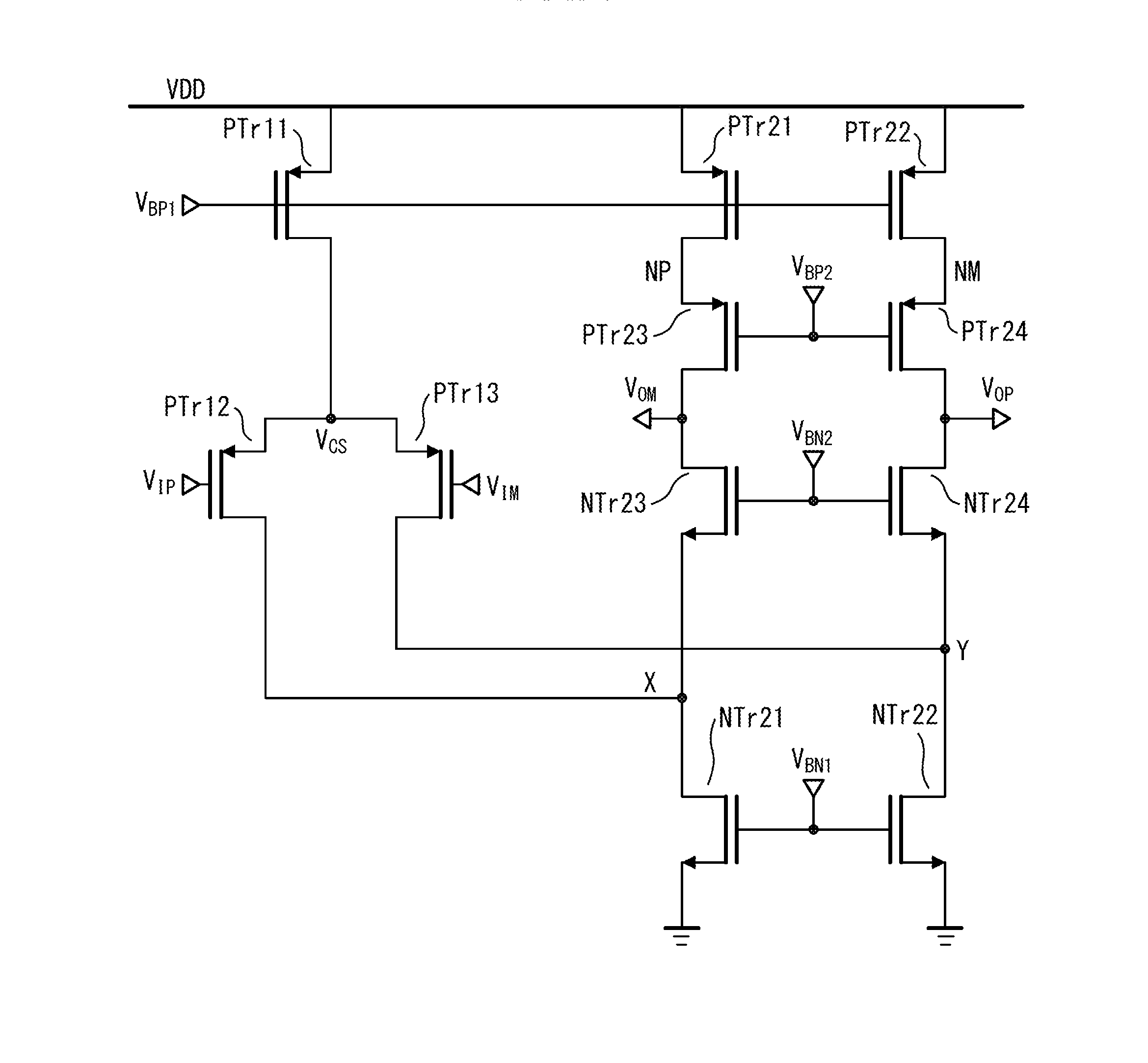
Hmm... Let's see. Topology described as: BJT Folded Cascode+Tube with CCS, 6SN7GTB outputs. Max output 325 VRMS which calculates to 920 volts peak-to-peak - this suggests PS supply of around +/-300 volts give or take.
So I Google searched folded cascode and came up with this image from a patent application - looks similar to the input and mid-stages of a Stax amp, but maybe with BJT input instead of FETs, and the CCS looks cascoded, so probably the output stage is similar to the SRX Plus, but without a tail current source. So, yeah, overall similar to a SRM-T1 with CCS in place of the output resistors, or a KGDT/KGST. Most likely passive PS, though.

-
2 hours ago, Ulfar4 said:
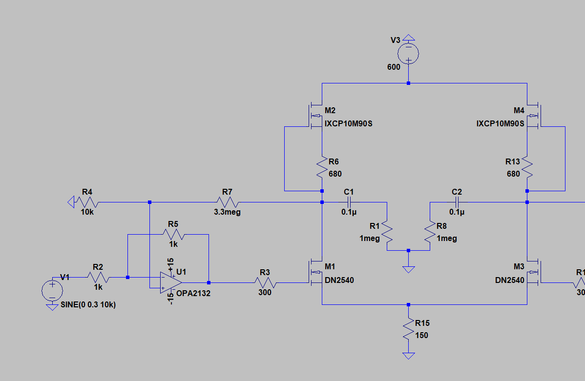
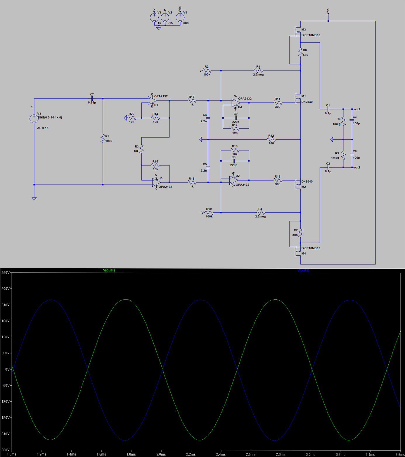
I was assuming that the 600V supply will split to 300V per side. So I put in there 10m90s as css. Is my thoughts wrong then? I redraw the feedback little bit acording to hev70. If I am understanding correctly, the feedback is there for setting the offset?
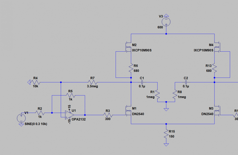
So, the problem is, even if the DN2540 sits at +300 volts, with signal, it can swing anywhere between ground and +600 volts with a big enough input signal. But the DN2540 is only rated at 400 volts. You should be able to see where I am going with this. Furthermore, as Kevin Gilmore points out, there is nothing in the circuit that sets the drain voltage of the DN2540 at +300 volts. The 10M90S current source is pretty much indifferent as to what the drain-source voltage of the DN2540 is so there is really nothing to control the quiescent voltage of the DN2540 drain. The feedback resistor really won't control it. I saw this in the SRX Plus, which uses 250k feedback resistors - there were times during de-bugging and adjustment when one output was nearly at B+ whereas the other was close to B- until I got things tuned up. That is tolerable with tubes because the maximum tolerated voltage is higher than the maximum rated plate voltage. Not so with MOSFETs or transistors - exceed the maximum for even an instant and you have a fried device. If that happens to your circuit on turn-on, it'll blow so fast you won't even know what happened.
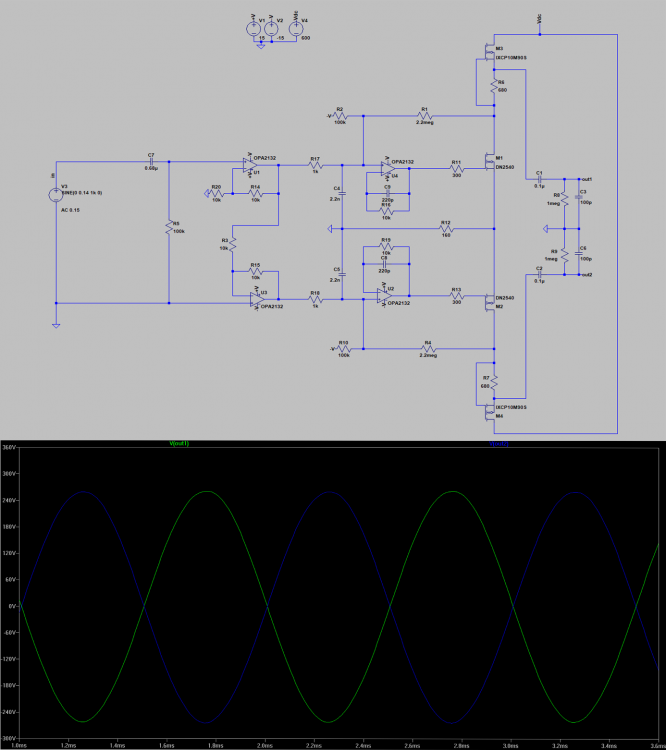
Take a closer look at the HEV70 schematic, it looks like there is a resistor network to set the quiescent output voltage.
-
10 hours ago, Ulfar4 said:
Hello everyone, I am going to build a DIY esl headphone but first I need some amplifier. I really do not want something fantastic, just to try out the headphones and then build something better. My inspiration was from John Broskie Tubecad schematic and head-fi forum. My question is will it play? And if not, what to change? Thanks for your help.
What I'm confused about is, why would you want to build a so-so amp just to try things out? It seems to me that a better solution is to get an old Stax SRD-6 or 7 adapter box, modify it to pro bias and drive it with a standard speaker amp. That is a known quantity, will be easier, have at least decent quality sound, and probably less expensive.
-
3 hours ago, justin said:
ssh i was trying to get JimL to do the T2 battery out of tubes (we can accept some neon)
Never going to happen. As Dirty Harry said, "A man's got to know his limitations."
-
2 hours ago, justin said:

do this one next
As I recall, that's the circuit that you tried to build, but found the OA2 tubes lost most of the signal?
-
Weren't you going to run a simulation of the SRX input circuit to see if its amplification was similar to a standard cascode circuit? I'd be interested to see what the results of that was.
As to the DNA issue, the SRX has a differential/long-tailed phase splitter input stage with two tubes sitting one on top of the other with the plate of the bottom tube connected to the cathode of the top tube (ignore the cross-coupling for a minute), and an output tube with the output taken off the plates. These features are broadly similar to the T2 in topology. The differences between a banana and a human is more akin to comparing a transistor radio to a T2.
-
Again, we are going to have to agree to disagree on description of the input stage. D.R. Birt, who first described the circuit in Wireless World, calls it "long-tailed pair using cascode stages with cross-coupling." Yes, there are additional stages in the T2, and the output stage uses grounded grid drive, but I maintain that the relation between the two is akin to the relation between a velociraptor and a T. rex. You can see the common DNA in the two.
-
Congratulations, indeed!
Now, as you may know, the T2's backbone is the same as the SRX Plus, it's just difficult to see because of the forest of solid state parts that surrounds it, most of them to replace two capacitors (per channel) in the SRX. So, now you need to build the SRX Plus and see how cheap and simple you can go and still get great sound.
-
 2
2
-
-
19 minutes ago, mypasswordis said:
Edit: sorry to JimL for crapping on your thread. Any new posts should go in the Carbon thread.
I was going to suggest the same thing, thanks. That's probably where anyone interested in an SMD Carbon would look first, anyway.
-
3 hours ago, Blueman2 said:
mwl168 or others,
With everyone's help, I was able to get my second SRX-Plus so stable that I went total OCD and decided to balance everything within an inch of its life. I ended up adjusting the 100R output CCS trim pots to get balance between + and - of each channel to be equal, and used the 20R pot to get offset to 0VDC. So after about an hour of warm up, all 4 outputs read less than 1VDC (measuring from GND to each of L+, L-, R+, R- outputs). I then adjusted the 500R pot to get upper plate voltage back to exactly 1/2 of B+. Fine tuned the 5K pot to keep plate voltages equal. So from these measurements, I think I have it dialed in about as good as I can.
However, this setup leaves me with about 3.3ma of 'extra' current sink between output current sink and source rather than the target 3.0ma . I assume that is OK, right? Here are my final measurements across the test resistors:
Output current loads:
- R+: 6.83ma
- R-: 7.00ma
- L+: 6.50ma
- L-: 7.01ma
Output current sink:
- Right: 17.18ma
- Left: 16.78ma
Input current sink (340V B+ rail, 300K plate resistors):
- Right: 1.07ma
- Left: 1.06ma
Does this all look OK given that the outputs are now balanced and offset to 0, and upper plates are equal and 1/2 B+?
No problemo.
-
Yes, I recommend floating the heater supplies. The input tube and output tube heater supplies also need to be separate, even if you rewire the input heater supplies to 6 volt.
-
Or you have more 12AT7 problems.
-
1
-
-
Hmm. Well, no. My prototype is single ended with the negative input tied to ground (I don't have any balanced sources, only single ended), and the plates voltages are equal. In fact, the original Stax SRX circuit has the negative input grounded. If you have a single ended input, you should balance the plates with the volume control turned all the way down.
-
The advantage of a simple circuit is there are only a limited number of things that can go wrong.
-
1
-
-
First, I would take the 12AT7 tubes from the bad amp and substitute them one at a time into the good amp. If the tubes balance in the good amp, then they are not the problem. While the tubes are out, you can re-check the plate resistors to make sure you didn't somehow put in the wrong values. Assuming they are good, that leaves the tail current sources. If that is the problem, I would replace all the DN2540s in both input tail current sources.
-
1
-
-
2 hours ago, Hopstretch said:
Extension cord -- 1000 euro a meter.
Hey, it's a German extension cord - gotta keep those unruly electrons in line!
-
I used something like that ground loop breaker for my phono preamp.
-
On 10/18/2017 at 12:46 PM, mwl168 said:
I have a couple questions reading the amp schematic on page 14:
1. The output capacitors - it shows two 100uf/370vac caps in parallel. Is there a reason other than parts availability/cost to not use a single 200uf caps? Also, what AC potential swing will these output caps see?
2. Any particular reason for the way C4 and C5 are located in the schema? Can C4 be soldered directly on top of C5 like the way C1 and C2 are?
Tube OTL amps are best used with high impedance cans as their output impedance is relatively high, in the case of the Menace I estimate around 50 ohms. If we use a Sennheiser HD600 300 ohm as an example, it is specified as 102 dB/volt, so 10 volts will give a deafening 122 dB.
Looking at the pics, I think the output caps C6 and 7 are motor run caps, as is C5 (note that all of these are rated at 370VAC, whereas C4 is likely electrolytic as it is rated in DC volts).
-
1
-
-
On 10/17/2017 at 6:14 AM, kevin gilmore said:
I do like dbel84's comment that the cavalli amps will be worth more now that production has ceased. Anyone know any RSA or singlepower amps that are worth more now than when they were new?
RSA is out of business? Just looked up their website, and there is a list of Christmas specials dated 10/17/17.
SRX-Plus Build Thread
in Do It Yourself
Posted
Glad your wife likes the SRX Plus.