astro
Members
-
Joined
-
Last visited
-
Thanks. Put T55D107M025C0060 in my pocket list. No sure exactly "High Temp Load Time" on the datasheet means. If it's endurance, then it just have half life span than Kemet. By the way, do anyone have any idea if there were any side effect swapping 20ohm output resistor with 10 ohm?
-
Found on Mouser. Still provide the link: https://goo.gl/eKbkSC The height is 4mm vs 6.9mm. Nearly double or just 3mm in difference! One alternatives is slim radial two leaded Al Electrolytic cap and let it lay down on the board. If so, the choice would become many many a lot, but mind the diameter. It will need more room on the bottom side in the case which makes it look bulky.(say over 10mm) Kemet 100uF/25V has almost the top capacitance in its own class(tantalum cap). This may explain the price. One more thing, the endurance. 25SVF is 1000hr@105C. Kemet T521 is 2000hr@105C and they also claim there is no aging effect. Kerry is right. In fact, when it comes to very limited space and relatively large capacitance to ceramic, tantalum is great.
-
The reason Kemet T521X107M025ATE060 being selected might probably just be the low profile. This cap is Al electrolytic on DIP dynalo, so I assume the ripple current rating is the major concern. My choice is Panasonic 25SVF100M, OS-CON series. Compare the specs: [Name] [DC Leakage] [ESR] [Allowable ripple current] [DF] [Price] Kemet T521 250uA 60mA@25C 100KHZ 2000mA@45C 100KHz 10%@25c 120Hz $3.56 each for ten more Panasonic 25SVF 500uA 24mA@20C 100KHz 3200mA@<105C 100KHz 12%@20C 120Hz $1.23 each for ten more pros: Half more ripple current rating. Half in ESR. Almost 1/3 in price. cons: Double in the DC leakage, but waste just 1mA more for 4 cap. DF are both bad. Barley fit the pad. 7mm in Height.
-
Agree. The final resistor value chosen is 220 ohm and get 18ma bias current. The final sink temp on the transistors is 74c~76c The regs are pretty hot, especially the negative one.(63c sink temp on positive/71c sink temp on negative) The top surface case temp is 38c. The ambient temp inside the case is 52c. Anyway still like this power solution.
-
Sure, left your email in message box. I'll send it to you. @Pars Hi, I left a message, but have no response. Do you still need them?
-
I tried aluminum heat sink before. It does have wider fin gap, but less fin count and much shorter fin height. The final stable temp is higher than the one you see in the pic. At last, copper has higher thermal conductivity. I have to say sorry that currently I have no capability to handle a group buy, but I would like to provide the drawing and seller link if you want.
-
@cspirou It's based on the @johnwmclean's layout. I just tried to post, but the server only allow me upload the file size below 20KB. Maybe send to your via email? Wow! Seems there are so many Taiwanese on this forum!
-
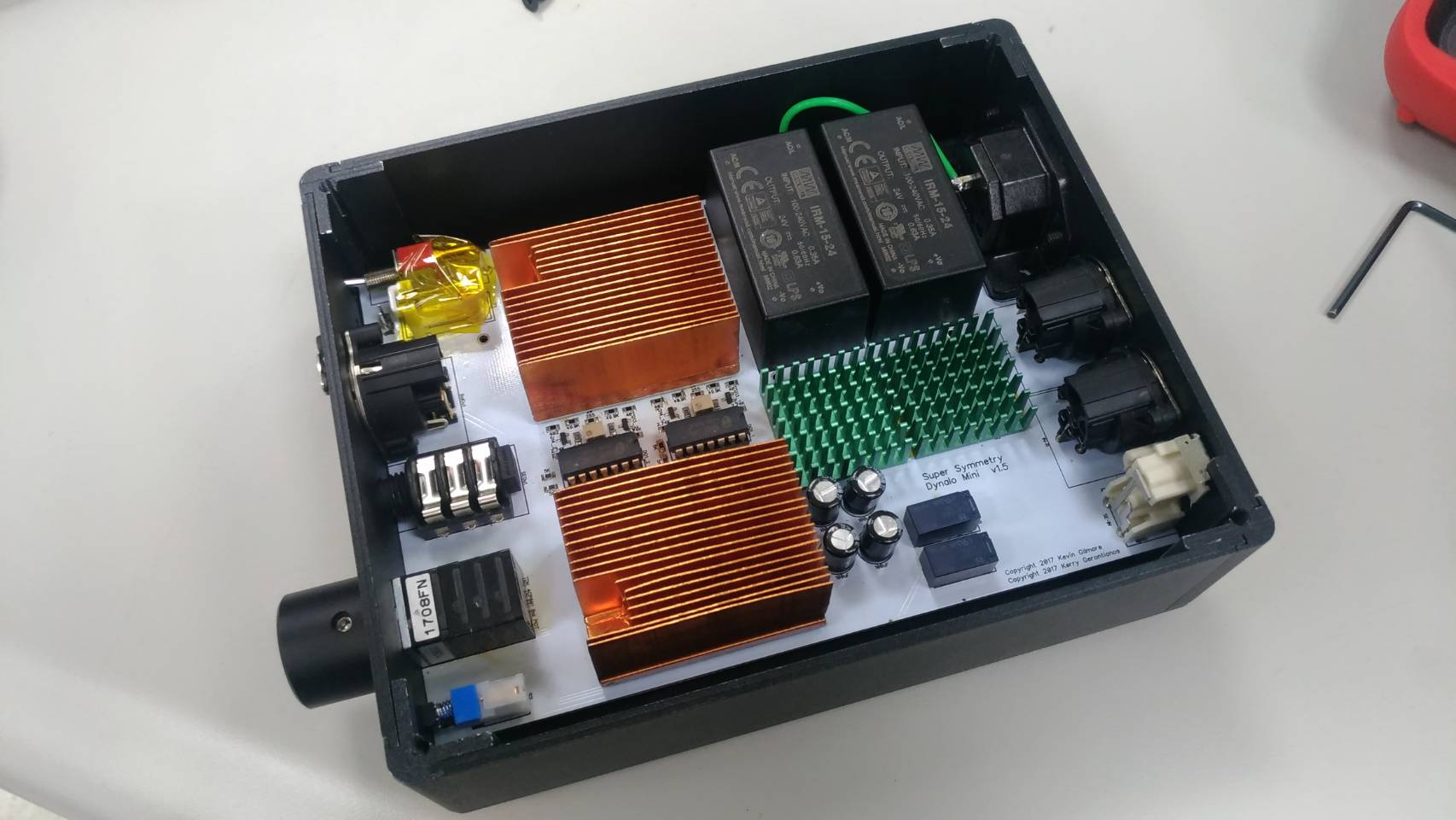
@gepardcv cspirou has already answered the question. Check the upper-left corner of the last pic where covered by yellow Kapton tape. @cspirou I draw the cad myself and place a custom order from taobao. The temp I mentioned is inside the enclosure and there are holes underneath for sure. Without the case, the temp will drop 6~8C.

-
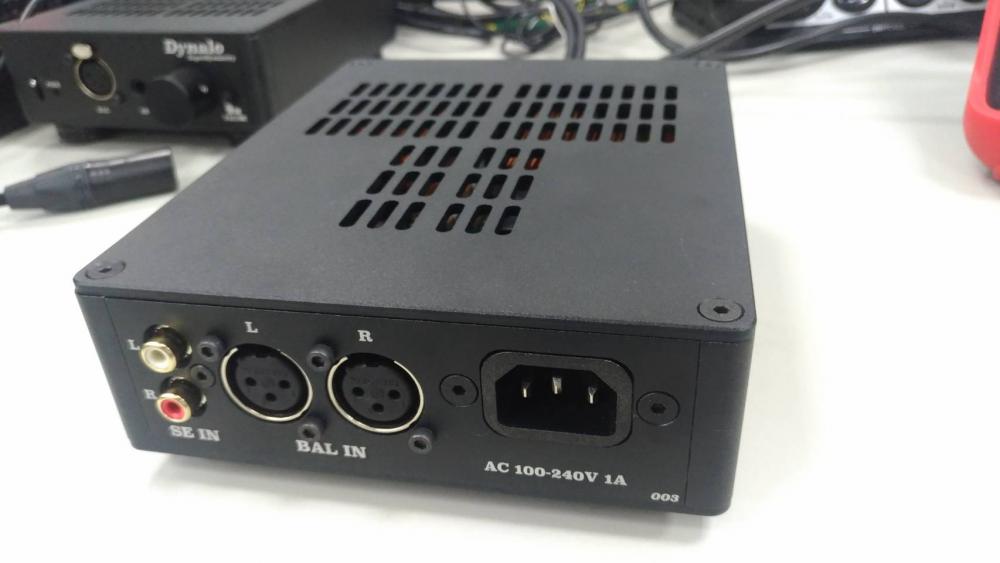
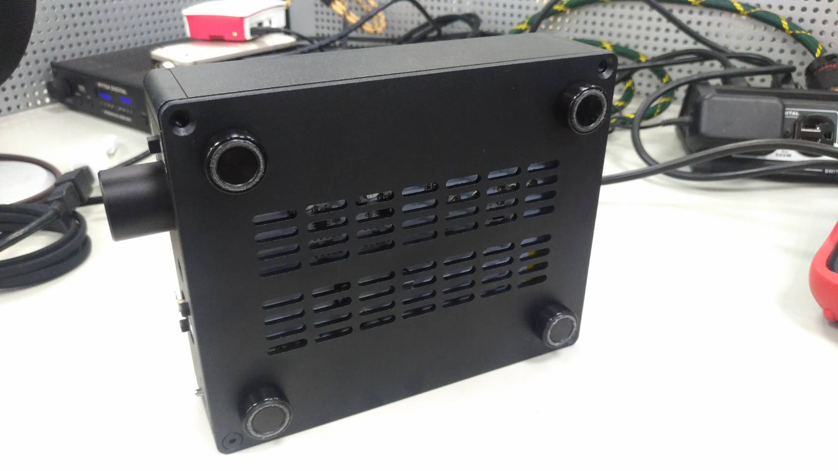
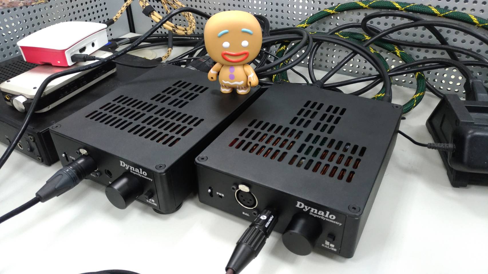
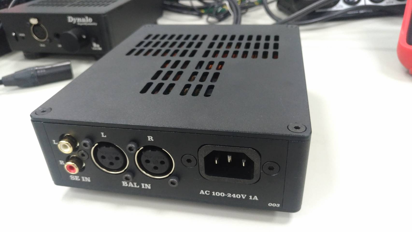
Hello, everyone. Sharing some phots of my recently built Dynalo mini. I have to thank Kevin, Kerry, and johnwmclean in the first place. My machine is pretty hot compared with others on the forum. The transistor heat sink temperature is 88c with 20mA bias(R14/R29 237ohm), 84C with 17mA bias(R14/R29 220 ohm) The IRM 15-24 power module is 16~18C cooler than the fin. The derating of it starts from 50C and shut down at 70C (ambient temp) This already makes me feel the amp working on the shutdown margin, though the sound is still fine. The forward voltage of D1/D2 LED is 1.794V and the R1/R3(increased to 453 ohm) cross voltage is 1.307V after warmed up which means the constant current 2.8mA. I remember the default constant current is 2.5mA, the Max bias current is 20mA and the normal bias is 15mA? Correct me if I'm wrong. Having no ideas about why my dynalo is hotter than other nearly 25C. Could it just cause by the higher hfe of the PZTA/MMBTA transistors? There are only minimum hfe value shown in the data sheet and no maximum is shown. I'll try 200 ohm and 180 ohm in the next week to see if I can lower the temp to 6xC.