woodear
-
Posts
12 -
Joined
-
Last visited
Content Type
Profiles
Forums
Events
Everything posted by woodear
-
this one is the first revision shown here on headcase: the one using Lundahl LL1690 and Jantzen Superior Z-CAP
-
Does anyone want the PCB files? I've just made some changes for the older version PCB. coupling transformers are removed to give place to coupling capacitors(ideally Mundorf Supreme EVO or EVO gold-silver, other axial caps are OK if the size fits the position). By using coupling caps, the amp is cheaper and easier fur DIYers. filament power supplies are no longer constant current source, as the actual working current of filaments of different tubes may differ greatly, making it possible for the voltage across the filamanet to exceed 6.3V±0.3V limit, so I swithced to a pair of simple LM7806 regulator using onboard heat sinks, which is more DIY-friendly(the previous version uses surface mounting TO-252 AMS1117adj as constant current sources, so you need the specially designed machined aluminum chassis for heat sinking). potentiometer is not connected to high-voltage bias anymore, which is safer to deal with than before. the large 1uf de-coupling film capacitor are restricted to 27.5mm pin-to-pin space film caps or 1uf Supreme EVO(silver-gold or aluminum), and the decoupling electrolytic caps are 22mm in diameter, which allows you to use larger value ones, for example, 100uf or 120uf. Althougn this is not a problem for myself, but the to252 surface mounting output MOSFETs are less convenient for DIYers than to220 package with on-board or off-board heat sinks. It's necessary to change that, but this takes some time..... and finally, the components are labled with R1, R2, R3, C1 , C2... it seems better to lable values and types of all the components directly on the board?
-
This is the new version of this ES. amp using a pair of Mundorf Supreme EVO instead of input transformers. When using coupling capacitors, the ground is not isolated anymore like a line input transformer with Faraday shield, and <1M grid risistors should be connected to the grids of ECC88 to establish a -420V DC bias voltage, which is the same bias voltage as transformer input version. This capacitor coupled version sounds more straightforward, more transparent, but with less "transformer distortion" which is a fraction of traditional "tuby sound". And finally, the finished amp with power supply unit in one of my friends home.
- 22 replies
-
- 10
-

-
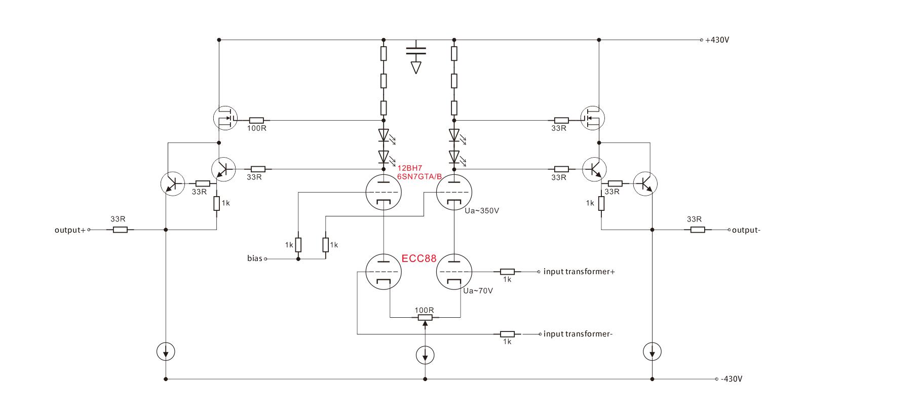
This is a detailed(relatively) schematic of the latest version. The transformer should be a 1:1 input transformer with proper insulation(1000V or more), and a Faraday shield which is connected to ground plane. the plate load resistors are 2 or 3 watt 62k resistors. The power supply ripple rejection(PSRR) of resistor load is low compared to a constant current source load, so I added an active de-coupling circuit using only one enhancement MOSFET, and a few resistors and a capacitor, which significantly reduce power supply noise seen by the 4 62k resistors. -360V and -420V voltage reference is simply generated by a series of resistors forming a voltage devider, which is not shown here. the 100R variable resistor connected to the cathodes of ECC88 is bypassed using a 1000uf bipolar capacitor paralleled by a 22uf smaller bipoalar capacitor, in order to achieve a higher gain and 'higher distortion' or you can say a more 'tuby sound' , you can cancel these bipolar caps if you prefer lower distortion and a clearer sound . the tail CCS of ECC88 is a CCS using DN3135, not DN2540 which is a common STAX mafia choice. The capacitance of DN3135 is lower than DN2540. Some of you might have noticed that, in this amplifier, the dual-unit RK27 potentiometer doesn't seem to be andequate to control the volume of balanced audio signal. In fact, the volume control circuit here in this amp is different from how we normally use potentiometers---- it's a parallel connection instead of serial connection, the audio signal flows through the 6k8 resistors, and then, directly flows into the grids of ECC88, potentiometer is connected in parallel with ECC88's grids. This volume control circuit will deliver more transparent sound as audio signal does not flow thru the dirty and noisy carbon-film RK27 potentiometer first, then into the amp. Another thing concerning safety operation is that, since the center tap of the transformer is connected to approximately -420V, the variable resistors inside an RK27 are biased to -420V too, we DO NEED TO consider if the potentiometer can withstand such high voltage between the internal components and its housing. Luckily, Alps RK27 and RK16 have an electric insulation of >500Vrms as shown on data sheets, so -420V is safe enough. The input signal impedance of a signal transformer is usually suggested to be as low as possible. I used to connect a potentiometer before signal goes into input transformer, trying to avoid high voltage insulation issues, but as a result, the bass is massively degraded due to increased distortion when the transformer is fed by a high-impedance signal. And here are pictures showing my PCB design. The components on this PCB are mostly SMT parts, except large capacitors, and tubes. Please note that the output MOSFETs and their CCS loads are TO-252 IXTY01N100D, the heat becomes an issue in this situation. I experimented 8mA current, and the heat was OK, as the MOSFETs are heavily pressed onto the bottom of an aluminum chassis through a 0.5mm or 1mm silicon rubber pad. For a better reliability, I limit the current to around 5mA(a bit more than 2 watt heat per MOSFET), which is enough current to drive(although not perfectly drive) a STAX headphone. If you want MORE current, you can try to-220 package. top layer(cyan) bottom layer(grey)

-
Sure, but I cannot upload pictures anymore, 500kB is all I can upload to this forum... Does anyone here know how to upload more stuff?
-
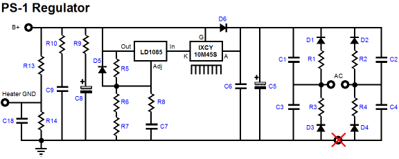
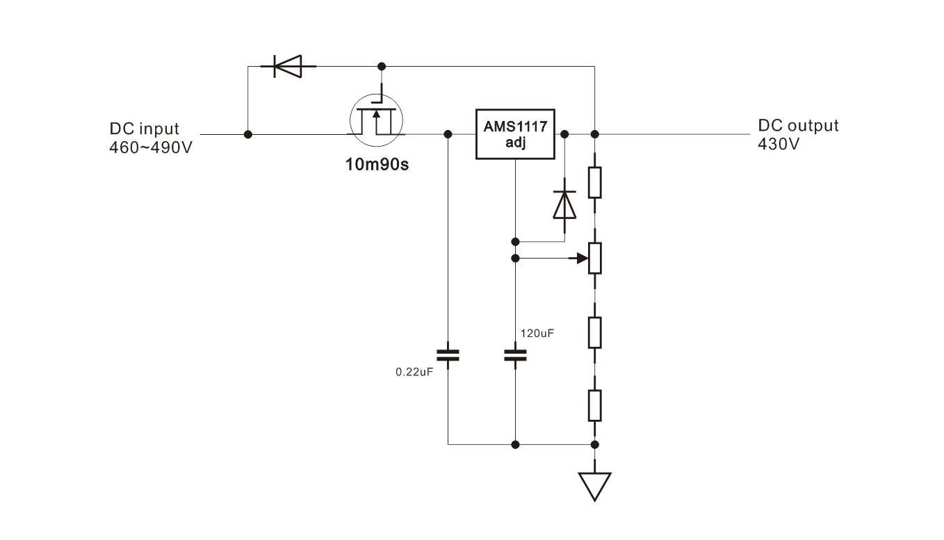
The high voltage power supply is regulated, using a HV reg derived from John Broskie's idea of using high voltage depletion mode MOSFET, together with a 3-terminal voltage regulator IC, to form a simple but high-performance HV regulator. I did some modification on John Broskie's original design I use AMS1117adj instead of LT1085. AMS117adj has lower drop-out voltage than LT1085, and the 3A output current of LT1085 is basically unnecessary.(and AMS1117adj is cheaper) The large 120uf capacitor connected to the ADJ pin of AMS1117 lowers output noise, and also act as a free soft-start circuit, this cap will be slowly charged for about 2 or 3 minutes, until the output voltage finally reaches 430V.
-
a 74kHz -3dB bandwidth is far more reasonable, the Cin of MOSFET buffer is certainly lower than 100pf.
-
Hi JimL, 1, the input capacitance of MOSFET follower is not simply the input C shown in data sheet, when functioning as a follower, the AC voltage difference between MOSFET's gate and source is quite small(Vgs of the follower is roughly a constant DC voltage, the AC component is tiny), so the equivalent Cgs will not be as large as when S is grounded. the drain of the MOSFET follower is connected to power supply, so the capacitance between gate and the drain is only 1 x Cdg, therefore the Cin=Cgd+Cgs(1-gain of the follower), the gain is very cloase to 1, as a result, the Cin is quite close to Cgd. Kung might have used some high current, high voltage MOSs which have much higher input capacitance than just 100pf. However, things will get much more complicated when the output follower is cascoded like Beta22, it is just not easy to estimate the input C in this application. I'll try to simulate the schematic by myself this weekend, hopefully, with the help of my friends(pathetically, I'm quite slow when learning a new software) 2, I tried different output resistor values, from the classical 5k1 to 33R, then I found a low output impedance will lead to a more powerful sound, since non-NFB tube designs are often less powerful than BHSEs or Carbons, and bass is often less well controlled, so personally I do prefer the amp with very high damping factor. In fact, a number of power/headphone amps claim they have damping factor of x00 to x000... what output MOSFET are you using?
-
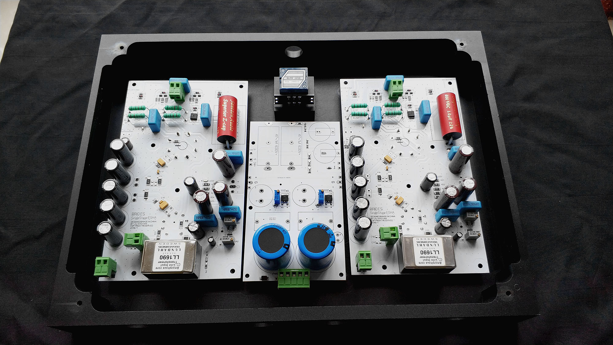
I've built 6 versions, and this is the latest one(PSU board not finished in this photo, and there is only one pair of 500V 180uf filter cap in side the main chassis, but the amp does have another pair of 180uf cap, and rectifiers and a 250W transformer in a separate PSU chassis, so altogether,360uf x2 for the HV power supply, which is perfectly enough capacitance). It sounds quite fast and transparent due to a single voltage gain stage design, when compared to other tube ES amps. And due to the low output impedance, the sound is relatively powerful sounding and the bass is tight, although it's not as powerful sounding as BHSE or KG GG. finally, it's a tube amp without global NFB, so you can hear the euphony of a non-NFB tube amp.
-
-
Hi guys,here is my hybrid e-stat amp design using only ONE cascoded voltage gain stage and a solidstate buffer which translate the high output impedance of the voltage gain stage into low impedance. The cascode voltage gain stage uses an ECC88 as input tube, for its low noise and high transconductance, and a 6SN7GTA/GTB to bear the high voltage(anode voltage is around 350V to get reasonable voltage swing). This stage will get approximately 200x, or 46dB gain. And please note that, the grids of ECC88 is biased at around -420V, so you can't really go DC-coupled, coupling capacitors or transformers have to be used. As most digital source components today have an output level of about 2V rms for single-end and 4V rms for balanced outputs, an amp with 46dB gain can output 800Vrms with a 4Vrms balanced input,which already exceeds the power supply limitation of nearly all e-stat amps of the world, so a 46dB gain is definitely enough to properly drive a typical stax headphone, although most e-stat amps' gain is 54dB or 60dB. Finally, there are many options for the output buffer, such as two or single stage high-voltage BJT buffer like SRM-717 or KGSSHV, or a simple MOSFET buffer like Cavalli's designs. But for this amp, I used a cascode output stage, which was inspired by Beta22 output buffer .
-
Enterprise is similar to T1 or KGDT, but the input stage is BJTs, not JFETs. Its high voltage power supply is classical Zener diodes plus MOSFET follower--nothing special, but the 580 bias voltage is supplied from a separate transformer winding and an independent voltage regulator while bias voltage of most electrostatic headphone amps are generated from positive HV power supply winding. Finally, Enterprise has a little OP AMP pre-amplification board, which amplifies the input signal before it goes into potentiometer. PS: I'm not the one who made Enterprise, but I know it a lot