MartinC700
-
Posts
18 -
Joined
-
Last visited
-
Days Won
1
MartinC700's Achievements
Member (2/6)
29
Reputation
-
Thanks I will give that a try.
-
Help with a KGSSHV Carbon Issue I posted information on my build in the Carbon build thread, and although I eventually believed the build worked fine, I do still have one recurring fault that I cannot trace. Hoping that someone who is more of an electronics expert than I can help with tracking down the issue. The problem only occurs when I am using a balanced input and only occurs on one channel. SE input works just fine with the amps - in grounded. With balance input one channel was distortion as well as what seems like a lower overall level. The distortion sounds like overloading and is accentuated on loud bass notes. I have checked all the input wiring and the source and it all points to something on the amp board. I have a DVM and a scope but am hesitant to poke around with the HV supplies connected. Any suggestions as to where to look for the fault? - Can troubleshooting of the input stage be done with only the +/- 15 v supply connected? Thanks for any help.
-
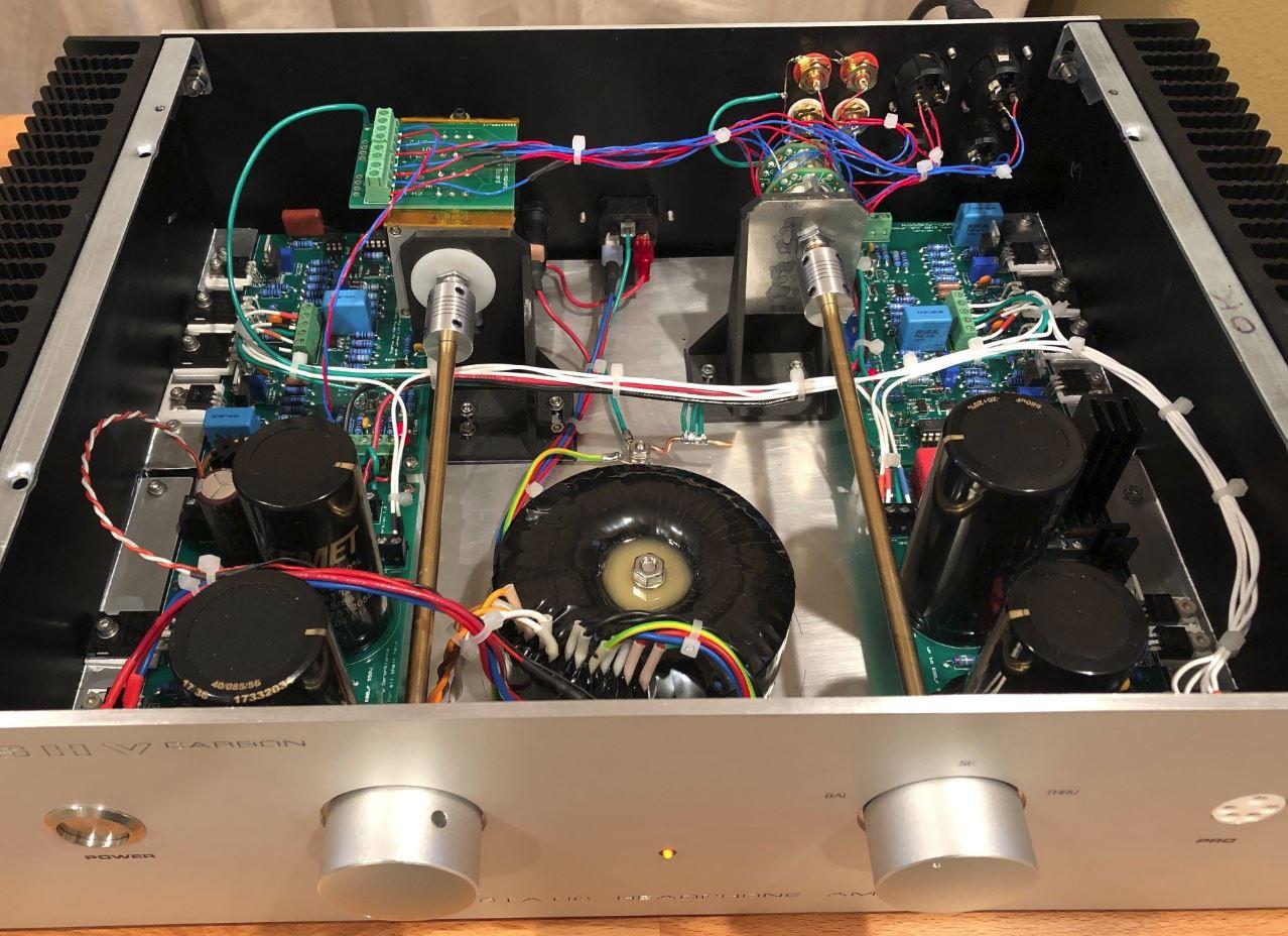
Quick Update: Fixed the issue. Not 100% sure what the issue was, tightened up all connections and changed out the XLR leads, and working fine now. Internal shot of the amp included if anyone is interested. Internal signal wiring is Teflon insulated silver (bought a bunch years ago at a surplus store). Custom PCB for the attenuator and 3D printed brackets for the switching and attenuator. Cheers

-
Thanks guys. I was a little too quick in thinking everything was working perfectly . SE input is fine, but when I hooked up via balanced, there is a noticeable distortion on one channel. It almost sounds like overloading the input, but is there regardless of the volume setting. I checked the source and that's fine when using balanced into the STAX amp. I assume that the issue must relate to the input circuity on the affected channel. Disassembling the map to get to the boards will be fun. Not too familiar with balanced circuitry so it will be a learning experience.
-
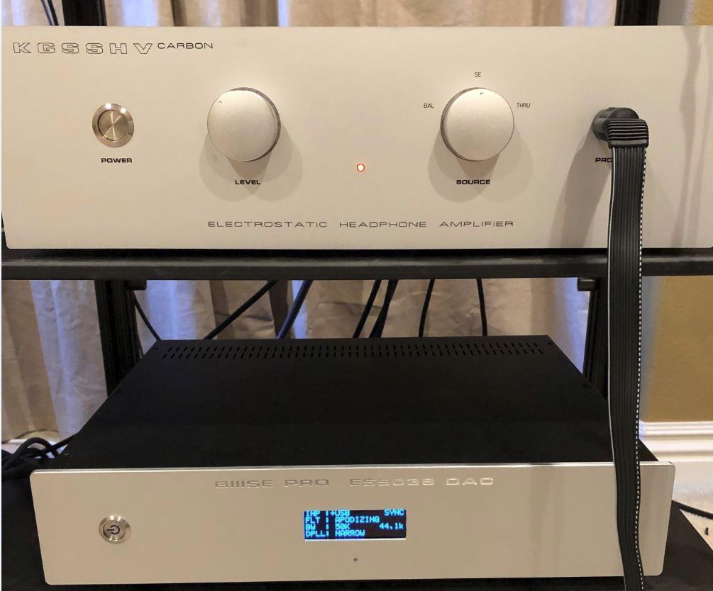
Firstly many thanks to all the contributors to this forum whos posts and direct assistance helped immensely with my amp build, there were a few issues on the way, but the amp is functioning perfectly and is a huge improvement over the STM-727II it replaces. There are many far more seasoned builders than I, but hopefully by mentioning a couple of issues I encountered it may help any future builders. 1) Check and double check your resistor values - I missed one and it resulted in quite a few replacement parts being needed. 2) If you are going to check voltages using your probe on the top of the screw terminals, tighten the screw down first (changed out the original 7815 regulator thinking it was faulty as a result) 3) You need the OP27 opamp installed even if you are using the opto servo to control offset. 4) The posted instructions mention adjusting the left channel balance and offset - you also need to perform the same operation on the right channel 5) I bought an inexpensive set of high voltage 12kv linesmans gloves from Amazon. Probably overkill but for the initial power up of the boards gave me more confidence in working with HV supplies. 6) Mentioned in another thread but Arrow Electronics offer most parts that Mouser have at lower cost and with free overnight shipping 7) If you need circuit boards, Easy EDA is pretty good at circuit layout and integrates with board manufacturer JLCPCB who are really inexpensive (read $2 for 5 small boards) Differences from what I would consider as standard build included: Replaced the 7815 and 7915 with AMB Labs Sigma 78 and Sigma 79 drop in circuits - soldering on the miniscule SM components is a challenge but aside from that they work really well. Used a ladder attenuator from Acoustic Dimensions, made a custom PCB to connect to it (I have 3 spares if anyone needs one). Installed input switching between single end and balanced, with also a feed through setting where the KGSSHV is totally bypassed. The SE input setting also connects the SE ground to the amps -ve balanced input. Picture is the KGSSHV Carbon with it's sibling a TPA Buffalo ESS9035 DAC built last year. Cheers Martin
-
Hi All, Build is near completion all seems to be working. One question regarding offset adjustment. After setting the offset to around 17v, after I engage the opto servo, what should the offset read? It reads around 15v, is that normal? I was expecting it to null but that's probably me not understanding the circuitry fully. Regards OK, stupid me! - Read through the thread and found that the OP27 needed to be installed for the Opto Servo to engage, all working now. Time for adding the attenuator and input selector and cleaning up the wiring.
-
Here's a plug for Arrow Electronics as a source for components. They don't seem to offer quite as broad a selection and Mouser, but pricing is generally better and shipping (at least to the US) is free and overnight regardless of order value. What is interesting is that parts in the same order often arrive in multiple overnight express packages from multiple locations. One order I placed had parts delivered from Las Vegas and Holland.
-
I will check when I am home but should have quite a few , I'll see if I have 16
-
Thanks for the info, but surely the pot ground must be connected to ground somewhere otherwise it is just acting as a resistor in series with the input?
-
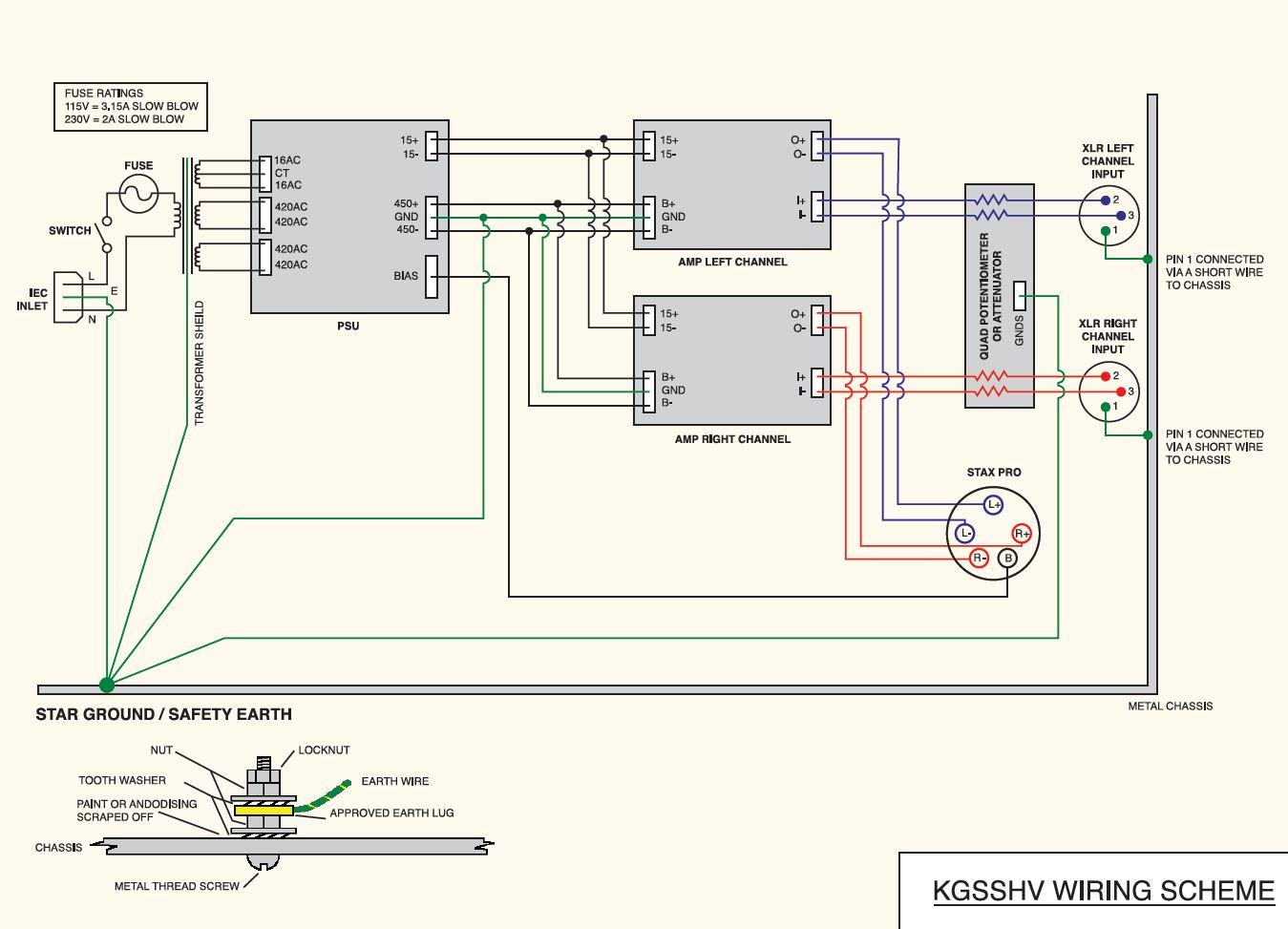
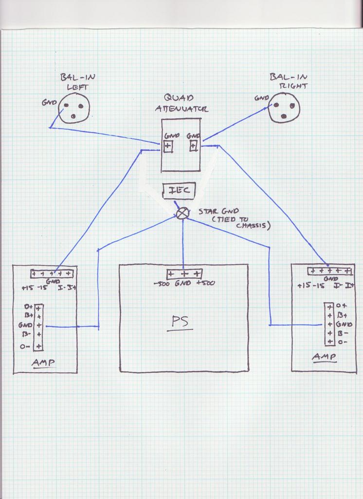
Now at a wiring up stage and one thing confuses me, and that is the grounding scheme. Numerous versions seem to be posted (two examples attached). Using the GRHV boards with the LV supply on one, there will be an additional ground to I presume the star ground. Does anyone have an opinion as the best grounding scheme? Regards
-
Sorry guys, another question. Using the LV supply to adjust the current by measuring the drain on the SIC's works, however I have an inbalance between the two devices, adjusting one for 18mA results in the other showing 16mA. Is this normal? (both boards show the same response). Did fix the HV supply by changing out all the semiconductors that could have been affected by the initial 50k resistor error. Also matched resistors for the voltage set and 408v and -407v Regards
-
Thank you mwl. Pulled the transistors and a couple do show dead shorts and quite different values from pristine versions. I am pretty sure which items are toast and will replace this week. Hopefully that will get the build back on track. Currently checking the KGCCHV Carbon boards to make certain all the resistor values are correct. Being very cautious with the board and checking that all caps are fully drained before working on them - thanks for reinforcing the warning!
-
Fired the board up again via the variac, got to around 350v this time and the 50k resistor at the same location as the original 50ohm one smoked. Checked the resistor type and its the correct 1/2W KOA Speer. I am guessing that the original failure must have taken out nearby transistors, perhaps the KSC5026 or BC557 pairs or the 10M90.
-
Some success, some failure! - One of the GRHV boards behaved, output slightly high at -408v as I hadn't matched resistors (will be swapped out once the batch of resistors arrive). The other GRHV voltage ramped up as I increased the variac to around 80v then shut down. Checked all solder joints, tried again and pop. Examination showed that I had accidentally placed a 50 ohm resistor in place of the correct 50k that is adjacent to the LT1021. Not sure what else may have blown, no visible damage, but as a precaution the plan is to put in a new LT1021 as well as replace the errant resistor, then power up again slowly using the Variac. I have spares for all the other semiconductors so those would be the next items to swap out if needed. Being very cautious as although I have but together quite a few amps, this is my first foray into HV stuff. (even using 1200v gloves).
-
Having embarked on a KGSSHV Carbon build, I have one question that I can’t find a full answer to on the forum. Because I have both balanced and unbalanced sources, I will be including input switching on the build. For the SE input the simplest option would be to merely connect the SE ground to the -ve balanced input and connect to the source with a pseudo balanced cable.Another option would be to add a couple of input transformers, which would apparently improve noise and hum rejection. The SE cables from the source are by necessity 17’ long so my guess is that the transformer option is likely the preferable option, would anyone have experience hooking up a SE input using both methods and care to comment? BTW thanks to the folks who have helped with advice and sourcing components. Regards