matthew-levi
-
Posts
31 -
Joined
-
Last visited
matthew-levi's Achievements
Advanced Member (3/6)
23
Reputation
-
I have been ripping my vinyls into digital files (96K/24bits). I found that they easily beat the CD version of those albums in terms of sound quality. You will probably need a high quality A to D converter to get the best results. I am using a Lynx Hilo with thunderbolt output which goes into my Mac. I have also used a PS Audio Nuwave Phono Converter. The PS Audio is currently collecting dust. The Lynx Hilo accepts XLR input. You can order a UBS output too if you do not want Thunderbolt. The software I use to rip the file is VinylStudio. Hope this help.
-
Hi CrowDaddy, Thank you for the encouragements. I will send you the BOM I used. I think its a personal choice on whether to use an EI or toroid transformer. It's a matter of availability for me. I have since replaced the transformer with one that can also supply the 15-0-15V and removed the smaller LV transformer.
-
After almost three and a half months, the KGST is finally in operation, and is sounding great. Thanks to all who have responded to my questions and given guidance. I am really surprised at how good the 40 year old headphone sounds with this amp. Special thanks also to Bigir and Dr. Gilmore for such wonder contributions to the community.
-
Yes, both O+ and O- behave similarly, and both channels behave similarly too. For the balance i manage to get it down to around 100mv or less. I will do more testing and run it longer to see how they go. Right now I feel better knowing its should be ok. Thanks for the guidance.
-
What should be the upper limit of the off-set ( between O+ and ground). It fluctuates from a couple of voltages to 100 mV range. This is after the amp has been running for about half an hour. When its so unstable, does it mean something is not quite right. One of my friends told me that the off-set should be in the 10s of mV range.
-
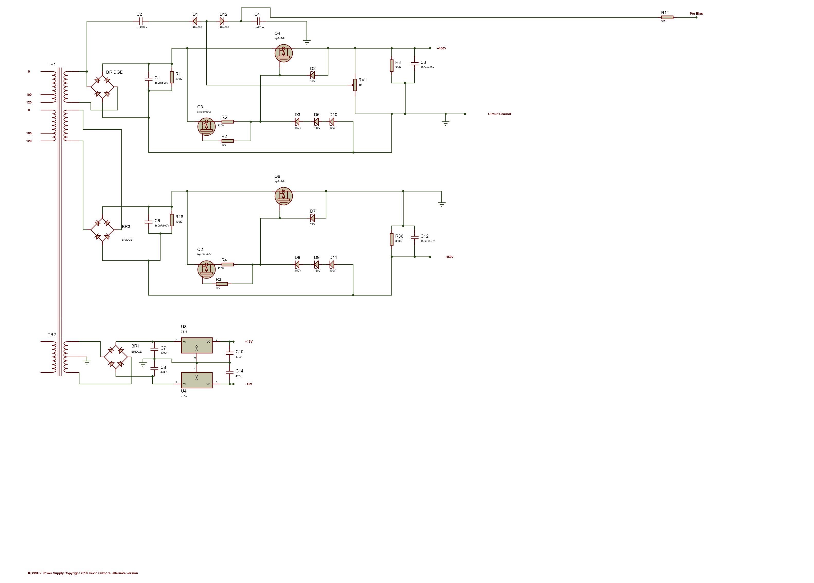
This is the schematics I downloaded from the web. On the board, I think the D12 anode is connected to the cathode of D1. So the board is correct, but the schematics may have an error (at least on this version that I managed to lay my hands on).
-
Love that warm glow of the tubes.
-
Hi JoaMat, I followed your advice and I have been able to set the bias to 230V. Thank you so much. For the balance and off-set, I have been able to set them to around 1V, but it fluctuates quite a bit. I think that should be ok.
-
I could not adjust the bias down to 230V (for my normal bias Lambda). The lowest I could adjust is 333V. How should I modify the voltage divider circuit to all the voltage to go down further.

-
Just want to report that the amp seems to be working, at least I can adjust the off-set and balance the O+/O-. I will let it run ahwile and remeasure/re-balance. The next is put together the case work and also connect the headphone connector and some music. I will report further once everything is up and running.
-
@Valve5425, thanks for the reminder about your addendum, I should have checked that first.
-
The terminal blocks on the boards are all from Mousser and they are Pheonix brand. I will check on the op amp sockets and see if I can order the ones you suggested. To all, I would still like to get an advice on no putting on the op amps to do testing. I actually could not see the op amp on the schematics that I found. Is the op amp optional in the operational of the amp assuming I can balance the DC offsets through the trimmer pots.
-
I am almost ready to test. The power supply seems to be working ok. With no load, the HT voltages are 368V and -370V. The low voltages are 15.07V and -15.09V. The terminal blocks will only be used for power to the boards, signal leads will be soldered directly to the input and output pins. I want to proceed to testing the amp boards without the servos. On the earlier posts in this forum, ppl mentioned about a jumper to connect the servo. But I dont see any jumper on this board. Can I just not install the op amp to disable the servo. I have put sockets for the op amps.
-
Thanks. That's the plan.
-
Thanks, mwl168. I just hate auto correct. Yeah, no need to appear. But I appreciate your comment(s).