


Satyrnine
-
Posts
132 -
Joined
-
Last visited
Content Type
Profiles
Forums
Events
Posts posted by Satyrnine
-
-
Any reason I can't use this with a 30v balanced CFA2 if I plan on driving small speakers with it? It's rated for 1A, 2A max, and 30w at 8ohm is right at 2A. Thoughts?
-
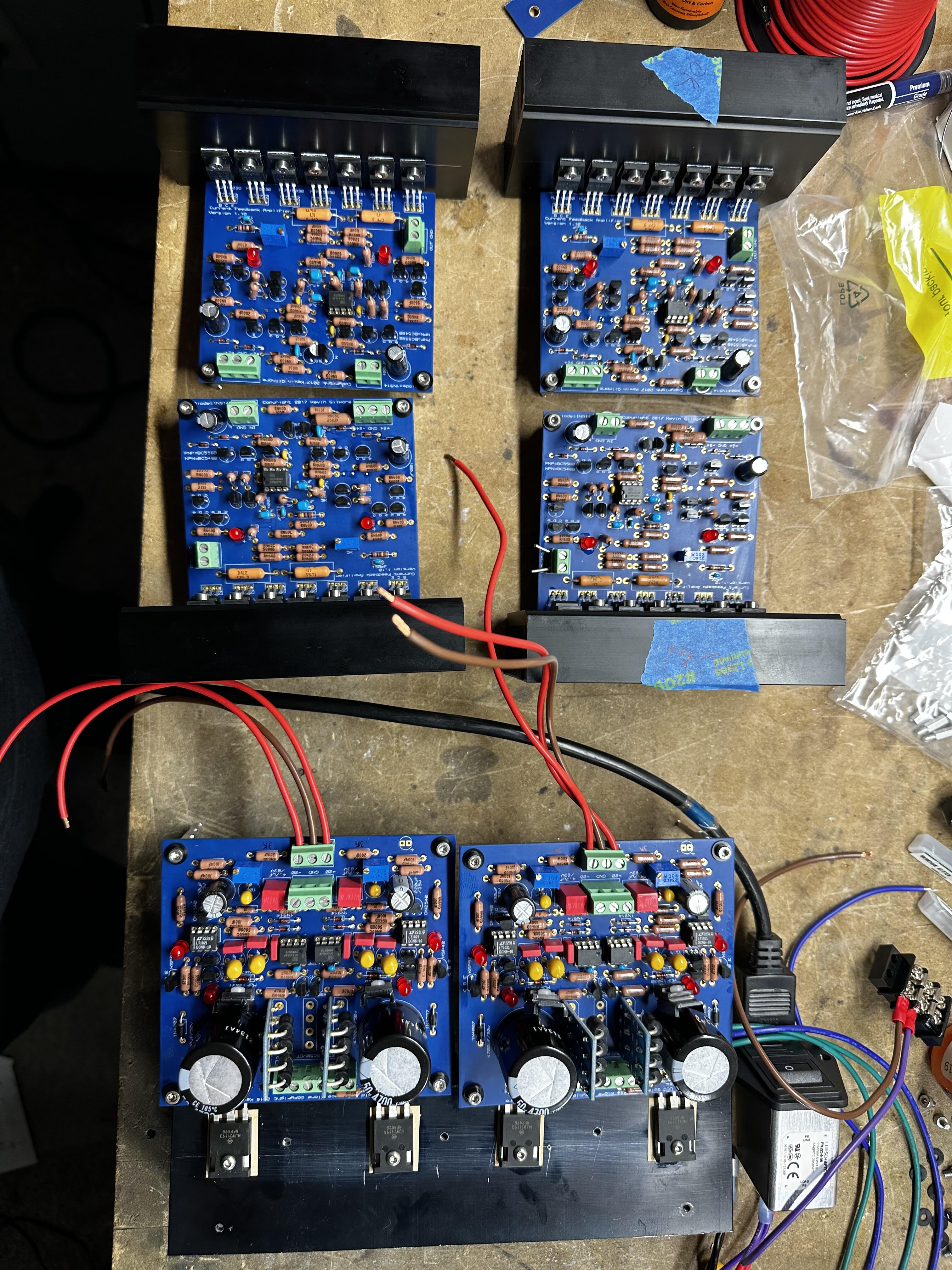
Last CFA board has spicy bias. With bias pot all the way down, I get about 150ma across the 1R's. That can't be right. The rest needed to be set around middle to get any idle current at all. Rechecked my P's and N's, and resistor values. Any thoughts? Suspect the middle (bias driver?) 15030? 🤔
Edit: replaced the middle 15030 with a slightly lower hfe version, dropped minimum bias to 120ma or so, so not the culprit. And then I shorted legs with my probe again like an idiot and popped the "last" 30/31's again. You'd think I would have learned something. I need probes designed for this clearly.

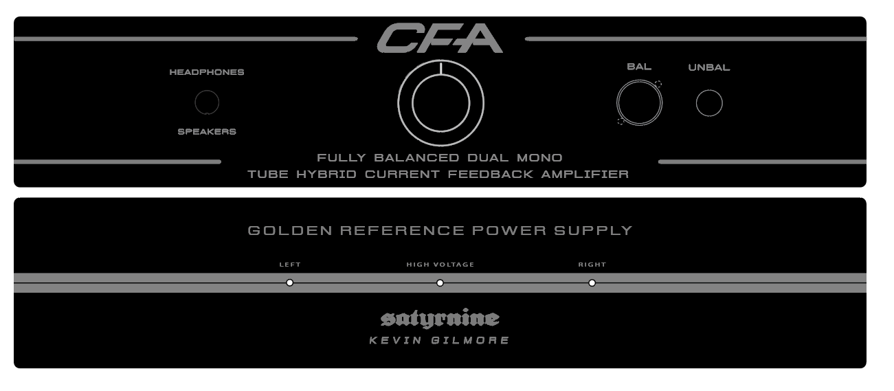
Here's latest chassis face design:
The horizontal lines would be deep machined grooves.
-
On 5/22/2023 at 11:19 AM, dip16amp said:
Just replace both 1 ohm resistors and the one bad 15030. Everything else should be fine.
Measure resistance across the 15031 and 15030 to find a shorted one.
I've only had a bad 15031.
Measure resistance across both resistors may be 1.5 ohms instead of 2 ohms.
Measure these in circuit with power off.
Thank you! This is great to hear. Was concerned it may have taken out more, I will measure everything! The one blown 1R is currently about 250ohms, haha! Will replace both though, as they both got to warm.
-
5 hours ago, Satyrnine said:
Fired up first two cfa2's last night. A couple issues:
Board 1) Without servo, I'm seeing around 400mv (!) offset on output with input shorted. If I plug in the opamp, it slowly comes down to 1-2mv over 30sec or so.
I started with bias pot all the way counter clockwise. Not seeing anything across the 1R resistors after a good 8 turns clockwise, do I just need to keep going, or should I be seeing some idle current by that point?
Board 2) LED's not lighting. It was late, and I gave up before investigating further.
Board 1) Butterfingered probing one of the 15030's trying to diagnose the high negative DC offset on this board. Shorted base to connector momentarily, 1R's went nuclear and started melting my probe tips within 1 sec. I powered down a second later, but I'm guessing I have some sand and resistors to replace now. Any suggestions on what to replace? Neat. Stupid mistake.
Board 2) Remind me not to trust mouser to always get their parts picking correct. Could have been my mess up too I suppose. There was a 10k in place of a 10R near the input (R9 or R10) which I deduce was causing the LED's not to light. Replaced that resistor w correct value, LED's light and this board is now showing around 40mv offset without opamp and zero offset with opamp, which seems about right. Biased to low around 80ma for now, just had to adjust trimpot further. This board seems to be good to go.
3 hours ago, audiostar said:400mV is around 10x too much for the offset.
8 rotations are normal for the bias pot until you start noticing the voltage increasing. The pot has around 30 turns or so. 150 to 200mV would be in range.
Indeed too much. Now that I messed this board up, may be replacing a bunch of sand anyway. I double checked my N's and P's and resistor values, and polarities before it went south, everything seemed to be in the right place.
-
Fired up first two cfa2's last night. A couple issues:
Board 1) Without servo, I'm seeing around 400mv (!) offset on output with input shorted. If I plug in the opamp, it slowly comes down to 1-2mv over 30sec or so.
I started with bias pot all the way counter clockwise. Not seeing anything across the 1R resistors after a good 8 turns clockwise, do I just need to keep going, or should I be seeing some idle current by that point?
Board 2) LED's not lighting. It was late, and I gave up before investigating further.
-
14 hours ago, audiostar said:
I would stick to 10k
10 minutes ago, Pars said:I haven't had any issues with the 25K, but I'm using JFET input on the DynaFET (only option). If you use the THAT BJT quads on an SS input stage, that would probably be a problem as those require low input impedance. CFA3 with JFETs is probably not a problem, though Kevin could clarify.
Thanks for the input guys. As a testament to their great customer service, Goldpoint is letting me exchange my (unused) 25k quad for a 10k quad, for cost of shipping only. Their shipping is prompt too. I haven't used one of their pots yet, but so far so great. My config will be just 4x cfa2 at first, and then the tube ubaltobal input once I get boards/bom/iron ordered up and together. Since it's a free exchange for the 10k, might as well take advantage I figure.
As mentioned earlier my legit dealer sourced 15031's range from 70 to 120hfe, approx evenly distributed. If it even matters, what would be the best way to distribute this range across my 4x cfa2 boards? If I recall correctly, one of the 7 sinked devices on each board doesn't get as hot as the main 3/3 set, should I put outliers in that position, or...???
-
On 11/24/2017 at 6:37 PM, Pars said:
What would the sonic effect be of running a 25K pot with this? It is what I have (TKD) in my DynaHi/DynaFET and I was planning on running these boards in that. I know you usually spec a 10K.
Thanks!
On 11/25/2017 at 5:47 AM, kevin gilmore said:Slight DC offset unless you match input parts. So a whoosh as you turn the knob
Just rereading some of this thread. So uh... lets say someone ordered a Goldpoint in 25k. How much of a problem is that. Asking for a friend. 😑
-
18 hours ago, JoaMat said:
Inspired by Satyrnine's project and an attempt to recover from my Tube input CFA3smd failure some time ago I’ve been busy with this today.
I call it Cascode Tube Input Something - intended for my CFA3smd something. +220/+15/-15V and filament needed. Based on ubaltoblatubeschem2, thank you Kevin.
So is this still the balanced/current mirror design of kevins but cascoded 6922's? I love it. Cascoded 6SN7's is one of my fav recipes. I have a SE pre setup that way, and it sounds great. I'm shooting for balanced all the way through for this build though. 6SN7's ideally should get more B+ vs 6922 obv, not sure how far down a that rabbit hole I want to go. Tempting as heck.
-
Here's one of Dukei's he sent me. Primo work as usual:
-
 5
5
-
-
1 hour ago, audiostar said:
Think about keeping it modular and separate the tube pre from the power amp. Same as you separated the PSU already and not stuff everything into a single like 6U 800mm deep chassis
")
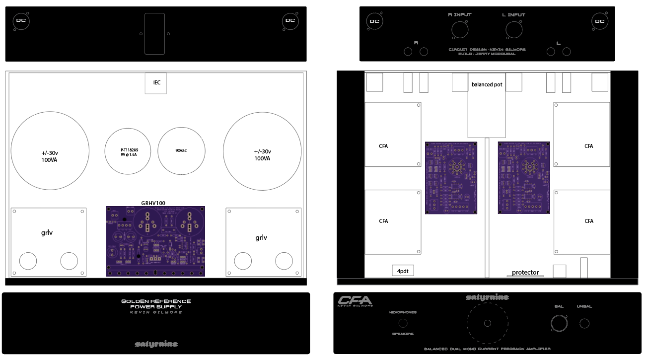
So you you suggest three different enclosures? Even with the tube pre in the power amp chassis, it would be only DC coming into the power amp chassis. Would put the tube pre powersupply in the PSU chassis. Are you concerned more about the 6v and 100v or some sort of other interference/issue I'm overlooking? So far, everything should fit in two 2U chassis, (one a pessante, one a dissipante) with plenty of room. Thank you!
-
1 hour ago, kevin gilmore said:
there are a few units with the tube front end that have been built. less than 5 i think.
boosting the front end high voltage will increase the power in the current mirror that follows the tube. so you might have to change some of those parts.
Sounds like something I don't want to mess with.
Thanks Kevin.
1 hour ago, Pars said:If it were me, I'd source 2 quads of Toshiba 2SK170/2SJ74 from punkydawgs on ebay, and just do the SS bal/ubal board with JFET input. But that's me. It seems like someone on HF has a tube input CFA3, but I didn't see any pics or direct posts by the person who supposedly has it. I know dukei has been talking about it. Kevin would probably know. A lot of the HF crowd seems to run a tube preamp into the CFA3 and use that to get their "tube" sound. I guess you could do that if you wanted.
I used to have a tube pre, a Counterpoint SA5.1, which used 6922s and sounded good. It had a slight hum to it which took me about 6-7 years to find (PSU board layout error), and I sold it right after that and never listened to it after I fixed it, other than to verify it was now dead quiet.
I feel like I need a shower now after being on HF for a few minutes

Just chatted with Miroslav/Dukei, and he had great things to say about the sound/performance of the tube bal/ubal input. I think I'm going to go for it. This will likely be my endgame amp, so why not go all the way.
-
14 hours ago, Pars said:
I don't know about going that high. Assuming this is a full wave bridge, you would have around 161 Vdc on the first filter caps. That is quite a bit of voltage to burn off. You could actually drop down to 80Vac and still get about 113Vdc, which would be plenty.
I wonder how easy it would be to adjust the reg output above 100v on the grhv100. I definitely don't understand all of what's going on there with the hv regulation. I was playing with the idea of using 6sn7's vs 6922's, which can handle quite a bit more voltage, and imo, sound a bit better. I don't want to make too much extra work for myself though.
-
10 hours ago, Helium said:
Any specific reason why you would put tube unbal-bal converter in front of CFA? Just to make it as complicated as possible? There will be ~100 more parts in signal path, hardly they will make amplifier sound better.
To make a CFA3. bal/unbal + CFA2 = CFA3 right? ignoring that I'm going w the tube version, Not much more components in path than a base CFA3 I figure? It seems people really enjoy the added ss/zf (zf only in the tube version of course) part of the CFA3, and if I'm going through all this trouble I figure why not go the full distance. Plus, having a little tube flavor on the input is always appreciated, since I typically prefer tube amps/designs. A balanced tube pre isn't common, so when I saw a tube bal/unbal, that seemed like a perfect match vs a standalone tube pre. Last, seems like not many people have built the tube bal/unbal, so figure I can be of some use by guinea pigging it. I figure this is the best of both worlds. Am I off? If yall think there's nothing to be gained, I'll consider skipping it. Thanks!
-
Was looking at this. 115v. Nice size, and toroid. https://www.mouser.com/ProductDetail/Triad-Magnetics/VPT230-110?qs=wkKrz7WmEgNNNgyT8w4YqA%3D%3D
-
6 minutes ago, Pars said:
Not sure if the Hammond has enough current capacity. Hammond 229B88. It's only 88V, 130mA.
The only issue with using 100V or so is a bit more heat on the pass device(s).
I was planning on sinking directly to the 10mm 2U front plate (along with 2x 30v grlvs) with good thermal compound. Think that'd cut it? Obviously "try it and find out" is the best answer.
-
1 hour ago, Pars said:
Also, I might have a couple of GRHV 100 PCBs here, though they aren't mine. I would have to ask the owner if he wanted to sell one of them.
That looks like the one! I would definitely be interested in buying one. I'm in Madison, WI USA. Thanks for suggestions on connectors.
1 hour ago, luvdunhill said:I also have run those voltages through Switchcraft EN3 series which I like a lot.
Excellent! I like switchcraft. I'll check all the options out. Many thanks! Since you ran those voltage, you don't happen to have a recommendation for a 90vac trafo around .5A or so? Seems to be a uncommon range. That is, unless I can use higher voltage ac than 90vac, 100-115 or so would be easy to source. Edit: nvmd on trafo rec. found some good options.
-
On 5/14/2023 at 7:39 AM, kevin gilmore said:
would need a higher voltage opamp. otherwise should work.
Excellent! What about the 90vac, and 8vac are they flexible too? 100vac seems a bit more prevalent in a reasonable VA. Or a 1:1 115v trafo would be great too. Will it reg down to 100v ok still? Same with the 8vac heater supply, I find a lot of 9vac trafos in a good size.
Here's a very preliminary mockup of what I was thinking. To anyone: Will bundling all these DC rails (6vdc, +/-30dc, and 100dc) together in a single multi-conductor connection work? Best connector for that? A bit new to external power like this.
-
Can anyone confirm if I can use a 100V secondary trafo for the grhv100? Will it still regulate down to 100vdc without issue? Having a hard time finding a suitable 90V unit that isn't 1A+/huge.
-
1 hour ago, kevin gilmore said:
grhv100 for the tube input stage.
Kevin, is there any way the ubaltobaltubeschem2 can be made to take +/-30 vs the +/-15? Otherwise I'd need a third grlv I think. Would be running 4x cfa2 from 2x grlv30. That is, unless a separate supply is recommended for the ubaltobaltube +/-15v requirement regardless. Also, suggestion for VA on the 90vac and 8vac transformers? I'd like to have 1.2A min available for heaters and 40ma plate current available if possible, to try 2x 6sn7's. (pinout is dif, but compatible)
-
Welp after all that work trying to stuff a quad cfa into a 3U, I think I'm going to add a ubaltobaltubeschem2 and grhv100, and go split chassis. Anyone have any ubaltobaltube or grhv100 boards?
-
Excellent, thanks everyone. Wow, The man himself responded to one of my questions.
-
Reading EL_Ken's post about grounding, (even though I know the incorrect grounding didn't cause a device failure in the end) I assume plastic shoulder washers are best to make sure boards don't ground to chassis through standoffs. Are brass or alum standoffs the best move, or would a nylon standoff/screw be a better option? I know it "depends" but does anyone have a suggestion for best size/height/etc for those?
-
56 minutes ago, swt61 said:
So, you haven't been here long enough to meet Brent?
Haha, I guess not.
-
A bit off topic, but I just have to say that this is the most knowledgeable, helpful, and BS free forum I've ever been a part of. Bravo everyone!


and now for something completely different part 3
in Do It Yourself
Posted
Oh! Excellent, love both options! My main work is with instrument tube amps which often have a bit more real estate, so my probes are not so small. I think part of my issue is there was no good place to rest my arm/hand to stabilize as I probed, since this is all out on the table in spaghetti form currently.