


Satyrnine
-
Posts
132 -
Joined
-
Last visited
Content Type
Profiles
Forums
Events
Posts posted by Satyrnine
-
-
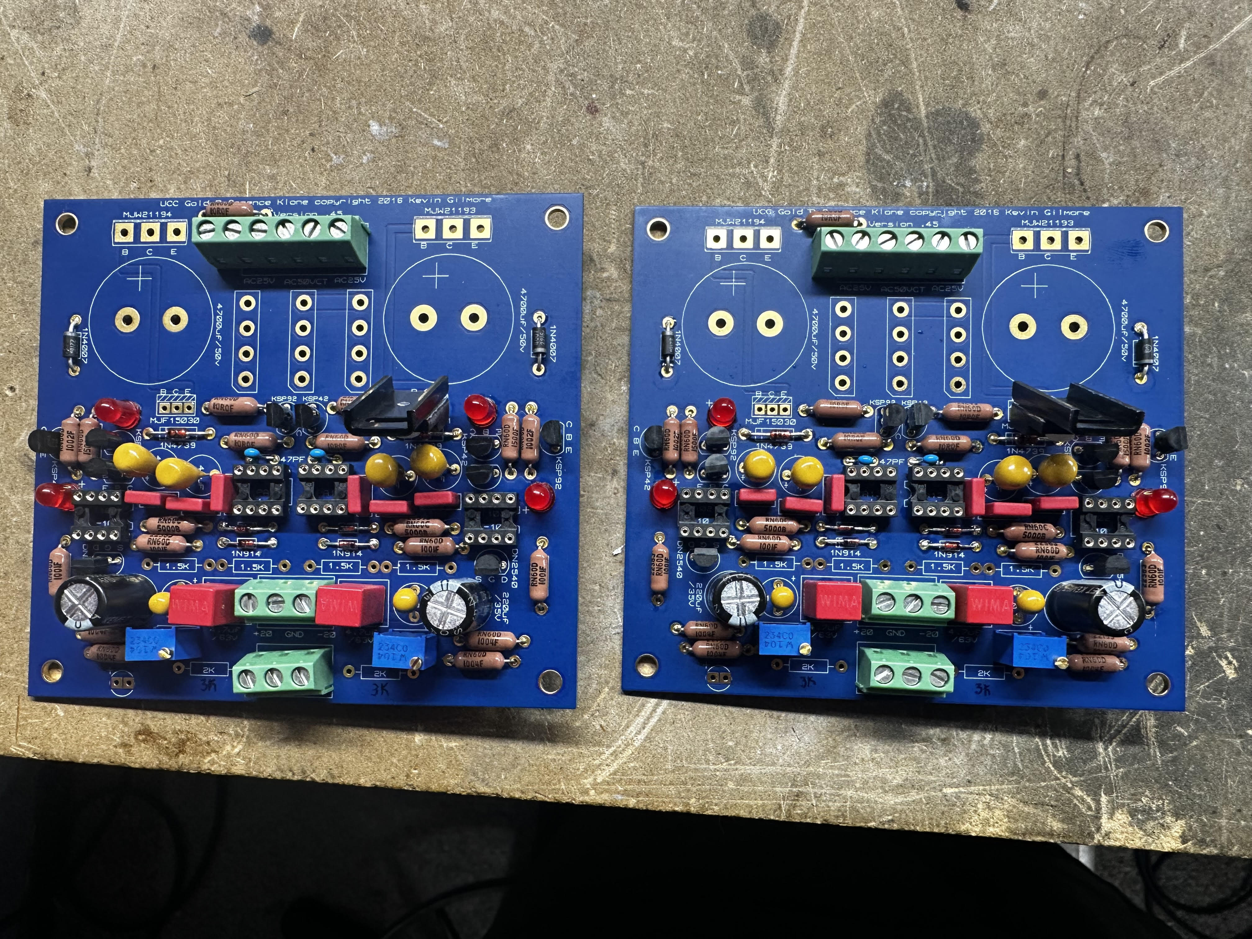
I started populating my grlv's tonight. I tested my MJF15030 and 31's and they vary quite a bit. I recall it said that matching isn't too terribly important, but want to double check. I know I'll get scolded, but I DID source the 30's from a seemingly legit and well reviewed ebay seller, since they are out of stock everywhere. I'm wondering if I got a batch of rejects. Here's what I found:
MJF15031 from mouser: All around 280hfe +/- 5.
MJF15030 from THIS ebay seller: 80-150hfe. Oof.
Visually they look identical, even with a loupe. I know that doesn't nec. mean much. Is this normal? If these are questionable, anyone have a source for 30's?
Also, the larger tantalums are 36v, not sure if they see full 30v or not, that's a bit too close to 30v if so. I ordered from an existing bom, and didn't catch this.

-
2 hours ago, audiostar said:
Well, reading the threads always helps. There is a ton of information in there.
Oh I did mostly, or I definitely wouldn't have made it this far, haha! I must have missed this one or overlooked thinking I needed to heatsink mount them with 30v.
-
 1
1
-
-
8 hours ago, johnwmclean said:
FWIW with 2 X 100VA the GRLVs are not going to run hot, you can mount them to the base plate.
2 hours ago, audiostar said:Not really going to work as there are caps on the GRLV boards. Maybe, with a 5U case 😎
The pass transistors you better mount directly to the bottom plate, like John has shown above. Oriented to center, straight below the Goldpoint stepper.
Well hell, wish I would have come across that photo earlier, haha! That sounds like a great solution. I'll set it up just like that. Thanks Guys!
-
Here's another idea. Mount the grlv sand offboard, and flip is on its side.
Mounting grlvs on top of trafo covers and remote mounting sand to sink.
-
1
-
-
12 hours ago, audiostar said:
I would not stack anything, at least not horizontally. In addition to what John already said, the upper board will always run hotter and also its transistor will be on the upper part of the heatsink already heated up by the lower row of transistors.
Stacking boards vertically on the heatsinks is much better, thus the reason for the CFA split boards.
Make sure you mount transistors to the lower on the sinks as heat moves from bottom to top.
I'm confused, aren't the split boards long and narrow, and designed to be stacked horizontally? Wouldn't vertical mount exacerbate the heat issue?
Was thinking a single 3/8" copper plate as an interface between devices and sink would act as a great heat spreader, reducing the heat soak effect of the stack configuration.
-
49 minutes ago, luvdunhill said:
Where the wires go into the toroid is probably the place to tweak a bit. Rotate them both towards the shaft if possible. The only other issue might be getting the wires safely to the 4PDT switch.
Yes, I was thinking mains in the center, and out on each side towards each grlv. As far as the 4pdt, it'd come from the protect board to the 4pdt, and then I was thinking speaker wires tucked along top or bottom edge all the way back to the speaker outs on the same side as the 4pdt. The back panel shows speaker outs on right, but it has to be rotated obv vs the drawing so they'd actually be on the same side of chassis as the 4pdt. I was planning on braid shielding pretty much every wire to chassis as well, unless that's excessive.
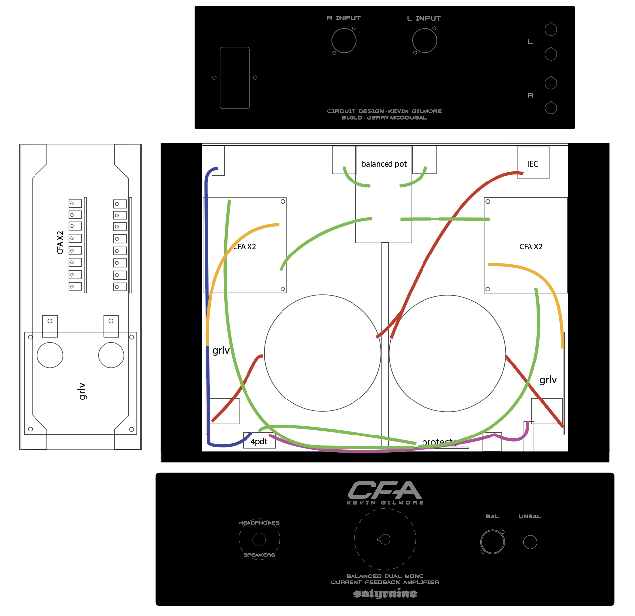
Edit: Here's the wiring mockup. Anything look problematic? Also, best solution for rear mounting a pot? First time doing so.
-
Alright, here's what I came up with. Any issue with proximity of IEC to CFA board on right, or the grlv to the bal/unbal outputs on front?
-
5 hours ago, johnwmclean said:
having the amps boards stacked like that you won't be able to bias the lower board if needed. Just ensure there’s adequate space, maybe longer standoffs.
I was thinking I could either use a horizontal adjust trimpot or a remote trimpot, but others suggestions might mean a reconfig anyway. Thanks!
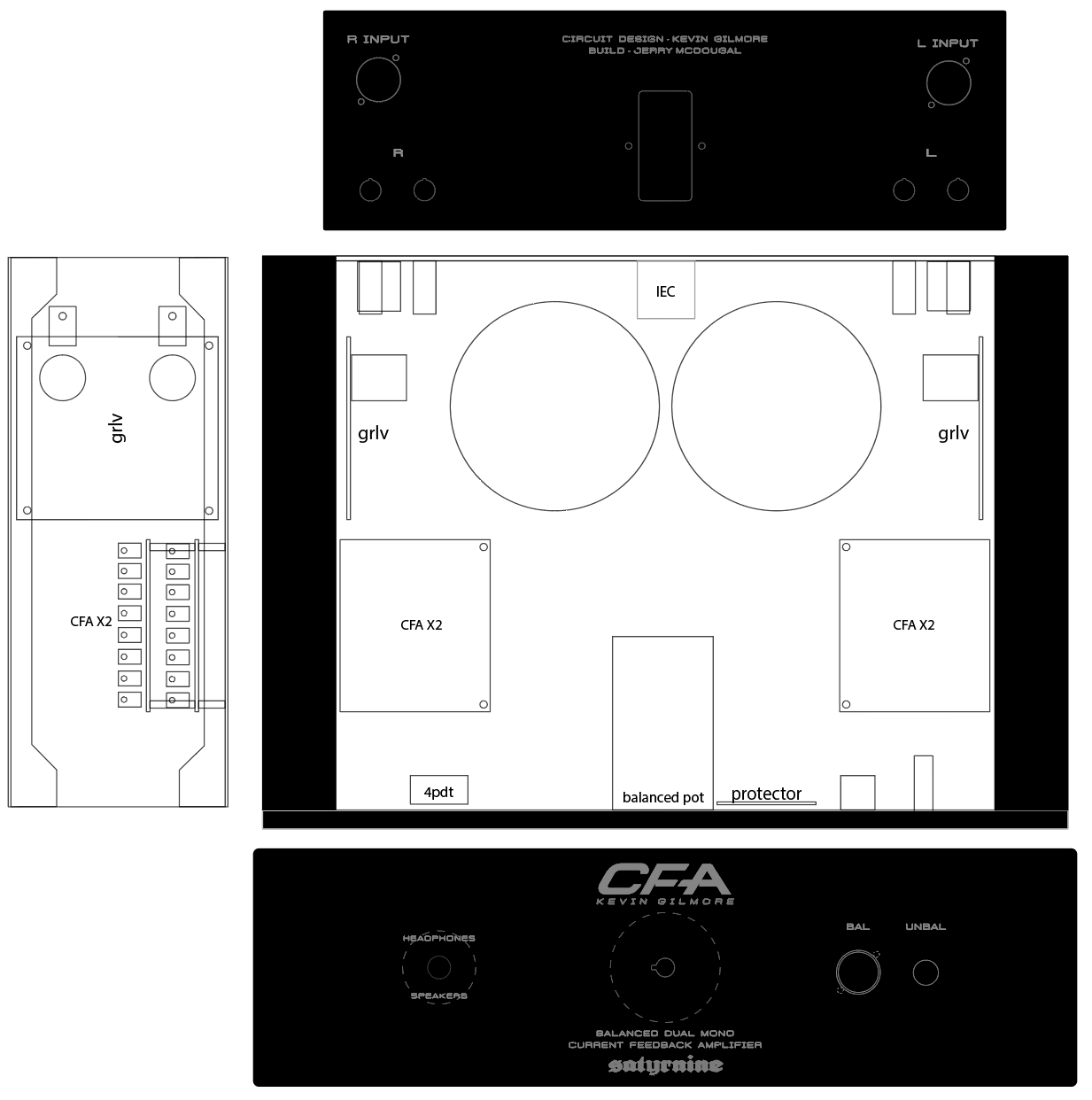
4 hours ago, Helium said:I would use different layout.
Move transformers and grlvs to the front. Move cfa to the rear. Keep DC protection board where it is at the front. Use extension shaft to mount volume pot at the rear close to inputs.
Side notes: move ac inlet to the left or right, it doesn't have to be on the center, it gives nothing. Stack the upper cfa higher so that transistors are distributed more evenly over heatsinks area. Move inputs closer to center (and to the pot) and move speaker terminals to outer edge of the chassis. Cause your speakers will be placed to the left and right and maybe quite far away from the amp.
Consider stacking transformers on top of each other, you have 120mm clearance if you don't use steel chassis.
That way you will have space to mount grlvs horizontally.
After all I don't think that amp with bjt output transistors is good to drive speakers. I would consider omitting speaker terminals completely.
This sounds like a good idea, I'm going to draw it up as you suggest.
I laid it out as is just to minimize distance from IEC to trafos mostly, since I don't have a front power switch, it'd keep it all the mains lines nice and isolated. Unnecessary? The rear mounted pot near inputs also sounds great though, so that probably trumps the mains being isolated/short.
I would only be driving small efficient nearfield desk monitors with this. I recall seeing others review it well for such use, am I off there?
2 hours ago, audiostar said:I would not stack anything, at least not horizontally. In addition to what John already said, the upper board will always run hotter and also its transistor will be on the upper part of the heatsink already heated up by the lower row of transistors.
Stacking boards vertically on the heatsinks is much better, thus the reason for the CFA split boards.
Make sure you mount transistors to the lower on the sinks as heat moves from bottom to top.
Thanks, will consider all this in new layout. In the last drawing I tried to keep them as close to bottom of sink as possible, but then as you say they are too close. Was hoping that direct-mounting the sand with a thick copper bar would help with the heat soak. I'll see what I can come up with. Thank you!
-
9 hours ago, Pars said:
Yeah, that could work, though I'm not sure why everyone breaks taps? Are you tapping by hand or using a drill? By hand, do a couple of turns, back out 1/2 turn or so, continue, rinse and repeat. I've never broken a tap, even on blind holes with a bottoming tap.
I haven’t either, just going by other peoples warnings I guess. I have a drill press I can use as a guide too. Maybe I’ll just mount direct if its not such a problem.
-
I'm hoping to mount output transistors flat to heatsink, although I realize this makes tapping mounting holes a rather arduous adventure. If I snap/jam a tap off in the heatsink, I'll have to move where I'm mounting boards, which would suck. I was considering a 1/4" thick by 2" bar of copper that I'd use as an interface. I'd lap both the bar and possibly the heatsink for a good joint and use some CPU thermal grease for a good thermal connection. A few big bolts to secure. Would use forming taps vs cutting taps since it's copper. Thoughts?
-
3 hours ago, audiostar said:
You might want to consider having only balanced inputs and *if* you need to connect a single ended cable to it, then use external Neutrik NA2 MPMF to convert a chinch cable. Will make things simpler.
The mount-from-inside version for the 3-pin XLR connectors for the inputs on the back would be the Neutrik NC3FBH2-B or the NC3FBV2-B with vertical pins.
For the speaker terminals, personally I would use the Neutrik SpeakOn. Would keep your back plate clean and can be mounted from inside as well into a round hole and are the best speaker wire connectors anyway. NL2MP or NL4MP-ST depending on what kind of connection from the inside you want and bi-wiring (4-pole) or not.
This will clean up your back panel with only 2 holes on the left and 2 on the right side. In the middle you can have the IEC inlet. Just a thought...
You're full of good ideas! Thank You! I love the adapter idea, will go that route. For rear panel XLR's, since it's less visible and I already have the jacks, I'm going to stick with they type I have. Will use the new style in the future for sure. For speaker terminals, I may keep the posts, as most of my speaker cables already have them. They aren't exposed metal at least, fully insulated, so less chance of shorting. Thanks again!
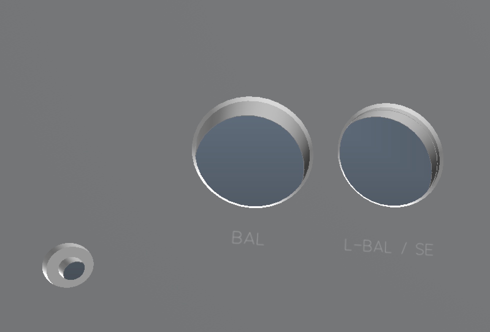
One other question. I assume I want to isolate the unbal out jack ground from the chassis, right? The jack I have is a switchcraft metal barrel type. Should be able to isolate it without too much trouble with some kapton tape and fiber washers.
-
Alright, here it is updated with the recessed jack with hidden tapped holes, and the inputs and speaker outs spaced better to fill the space opened up by moving the grlvs.
-
4 hours ago, audiostar said:
So, you will be running single ended wiring from the back panel's RCA connectors alongside the transformers all the way to the bal/unbal board located at the front panel?
I should clarify, because it's not clear, the stacked holes labeled just R and L are speaker jacks, not RCA jack holes. I didn't want them too close to either the inputs or the mains. Thoughts? RCA's would be the labeled SE input further to the sides. I do need to move the inputs further to the sides now that there's room to do so. Good call.
I'm forgoing the bal/unbal board for now. (Had a hard time finding good input jfets, and Dukei suggested I try it without first) But yes, I'd run them around each side to the vol pot first, then off to CFA boards. Was planning well shielded Ag/ptfe for the runs fwiw.
The SE inputs would be parallel to bal inputs. Flipping the switch grounds the neg boards inputs, and then you get SE output only. For the outputs, a 4pdt. Planned on running the speaker leads centered near the top of the chassis, or possibly back around each side of the trafos. Any input welcome!
4 hours ago, audiostar said:Here an idea for further builds: I am using the Neutrik NC4FAH-0 connector and mount it behind the front panel using blind taped holes, same as with the teflon Stax sockets. The hole is 22mm in diameter and for any panel thicker than 2.7mm a beveled edge on the front is a nice addition. Here the panel cut out and dimensions for the NC4FAH-0. If you do not PCB mount the connector, the NC4FAV-0 would be the vertical pin version where the contacts might be easier to solder wires to. Front design and dimensions are the same. These connectors don't have a locking tab, which is nice as well.
Wow, I think I'm going to convert to this actually, that's a far better look. Thank You!
I wish they made a female version of this.
-
Alright, here's the new idea.
-
2 hours ago, audiostar said:
With this 19" 3U case the amp will look like a 100w class-A power amp.
A better idea would be to separate the PSU from the amp.
Also, 100VA toroids aren't giant, I wouldn't be concerned about mounting them with 4 or more bolts.
Depends on how thick the plate is. Dissipante panels are only 1.5mm I think, so this makes sense. Wouldn't be concerned though mounting the 100VA to 3-4mm thick panels. But don't use countersink bolts, only buttheads so you do not weaken the hole. Will be on the underside anyway.
I'm going with aluminum panels, so they are 3mm aluminum. The steel are thinner though, obviously. I figure a 3U chassis isn't much bigger than two separate chassis though, no? The extra heatsink on the 3U for speaker use was my thoughts.
The toroid cans are a single bolt, but the edge of the can is flush with the chassis, so any lateral force would be more distributed and less likely to bend the mounting plate, vs a "roundish" toroid without a can/cover.
2 hours ago, Helium said:Here they are.
Consider 2-storey layout, where CFA boards are mounted on top with each other and to L-brackets on heatsinks.
This is what I have in mind for my CFA3 project.
This is fantastic, thank you! I'll mock up the layout and see if it's feasible. If not, I'll change up the design. Many thanks for this! Edit: Yep, not going to work as I had it drawn. Thanks for saving me a lot of headache!
-
This is great, thanks Helium! You don't happen to have dimensions of the bracket do you? Edit: I may be able to determine dimensions from that top view by measuring off it and scaling. I may be able to make it work, considering I'll be cutting off the parts of the CFA boards where the transistors would typically lie, would give me some extra room. As Dukei said "it will be a tight fit, patience will be key" haha!
I mainly wanted a better thermal connection from transistors to heatsink since I'll be driving speakers as well. Coming from IT, thermals are always on my mind, although maybe unneccessary in this situation.
As far as the trafo mounting goes, I might add a plate under them for a bit of stiffening. Maybe drill a few more mounting holes in the bottom plate/brackets to connect it more securely. Only 4 bolts is indeed concerning. I just personally don't care for the looks of the steel bottom plate, although it would be very convenient that's for sure.
Thanks for your help here!
-
5 hours ago, Helium said:
I used modushop dissipante quite a few times. I doubt that you will be able to mount boards on side heatsinks this way. Have you accounted for steel support brackets that take up significant area of the heatsinks, and use of steel chassis on the floor? Since you are mounting transformers on the floor it's good practice to use steel chassis (sold separately) to get extra rigidity.
I haven’t, thanks for the heads up, definitely the reason I posted here before finalizing/ordering. Thank You! That said, Dukei is the one who suggested it, sounding like it was possible. I’ll touch base with him on those concerns and either redesign or report back with a possible solution.
As far as the steel floor chassis add on, this is good to know too. The trafo covers i ordered through antek are nice and beefy and support/clamp to the bottom plate around the edge of the cover as well as via the thicker/wider center support which maybe would prevent/reduce any rigidity related issues vs bare toroid? Def open to the add on support, but prefer not to if possible, if only for aesthetics. Since I’ll be assembling myself I don’t have to worry about shipping with trafos installed at least.
-
One side question: My understanding is that Nichicon MUSE/Fine Gold, or SIlmic/etc caps are inferior to power-supply specific caps for rails usage, no? Always thought they were for audio path/coupling use when needed, where an ultra low ESR, high mtbf hrs, and high temp (105c) cap is best for rails. I have just seen MUSE/FG/etc in places I'd usually choose a psu cap for. Am I off here?
-
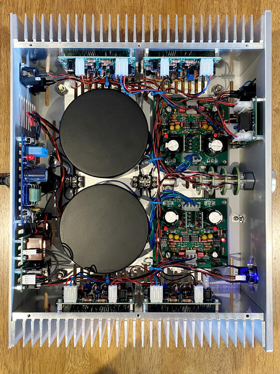
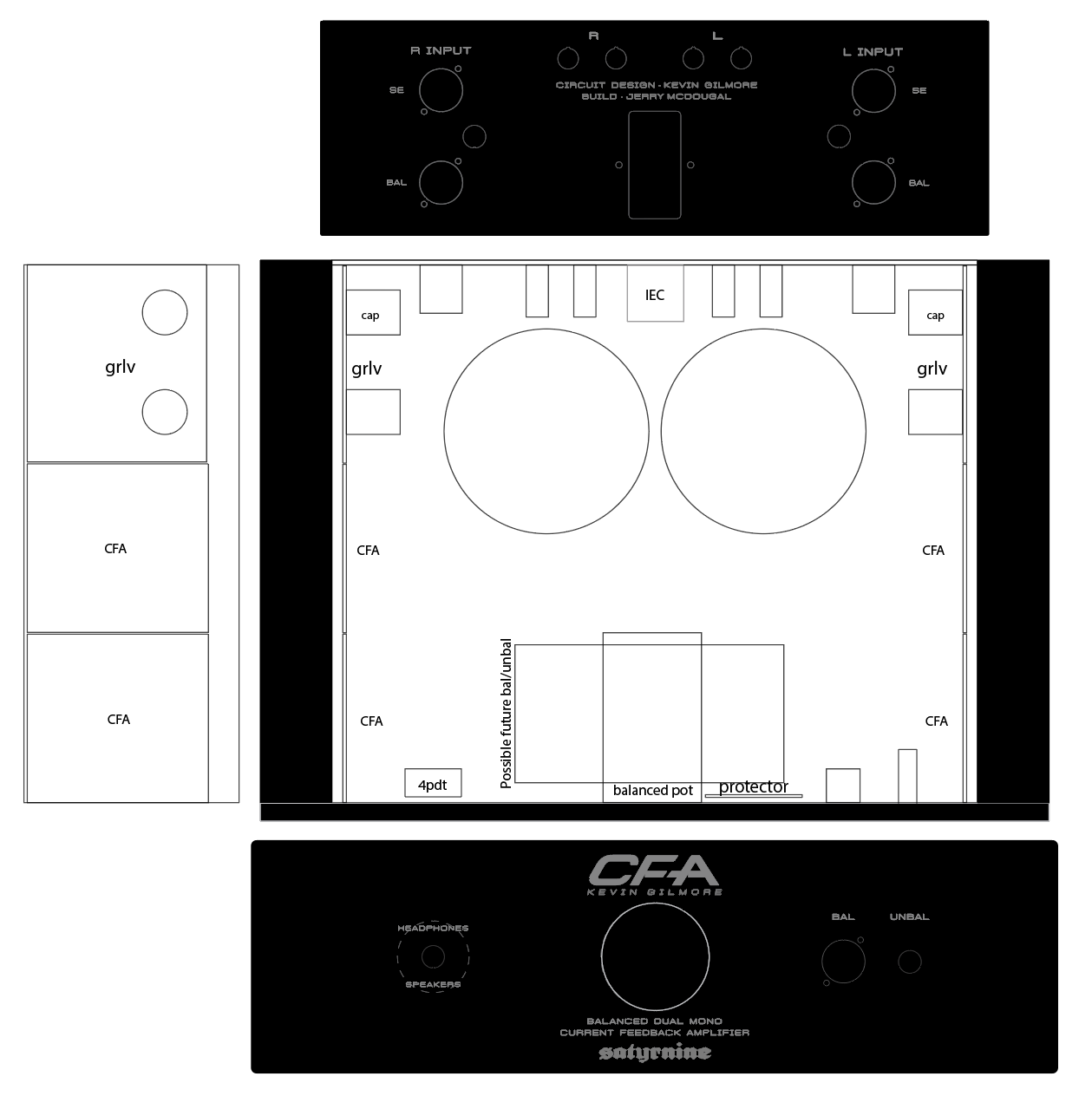
Almost ready to start building my CFA2/3!
- Dual Mono, 2x GRLV, 4x CFA2 boards, and maybe a bal/unbal down the road. I plan to use this with my LCD-2's (orig), and my desk monitors via added speaker outs. I have all the components on hand but the chassis so far.
- Details: Dissipante 3U chassis. Mounting boards directly to heatsink.
- 2x Antek 100VA 30V trafos with steel covers
- MUR820 Ultra Fast diodes on daughterboards vs standard GBU4 package rectifiers for GRLV boards
- Goldpoint quad/balanced stepped attenuator
- KG Headphone Protector Board (just had a set made at Oshpark)
- Options for Bal and SE in
- Bal and Unbal outs (unbal out only works with se ins in CFA2 mode obv)
- Dale RN60 resistors throughout, Used Pars's BOM
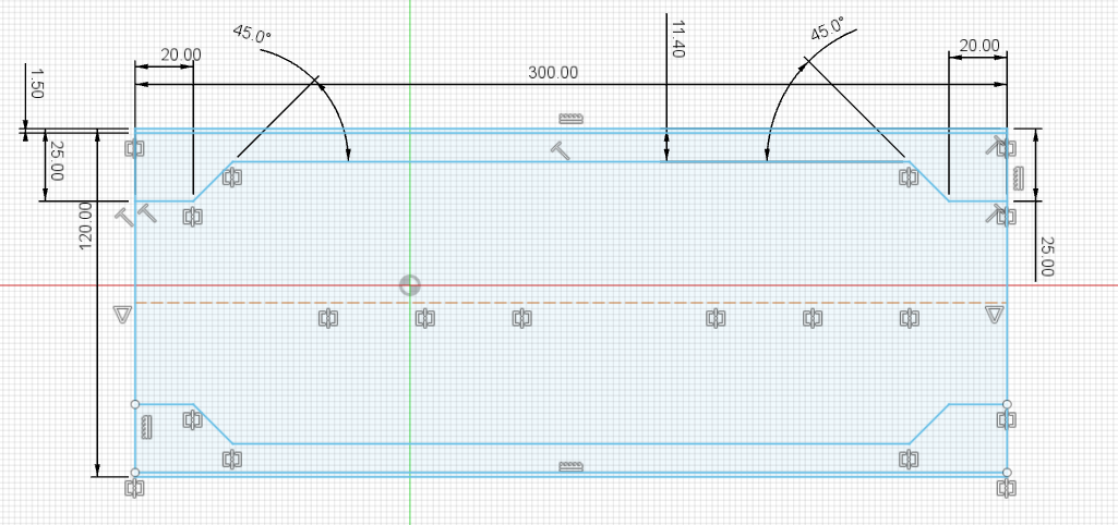
Here's what I have drawn up so far for Front/Rear panels I'm having made at Modushop, as well as internal layout plan thus far. Getting panels engraved/machined, with the "CFA" cut deeply at a bevel. Large circle where vol knob is is just a placeholder for the largest possible size knob. Dotted line around headphone/speaker switch is a rear recess since front panel is 10mm thick.
Many Thanks to the infamous Dukei/Miroslav and Pars for guidance, as well as arteom from diyaudio for generously supplying boards, and of course the man himself for this awesome design.
-
1
-
On 4/22/2023 at 10:18 PM, arcanaking said:
Hi all, sorry for requiring the pdf/gerber. I am trying to build my CFA3 with the balanced audio protection board. Yet, it seems hard to find the gerber or pdf of the protection board in other threads. Can anyone tell me if it is a must to use the protection board? If yes, where can I find the document?
https://drive.google.com/file/d/1wsVGv82qhTbcngFUPGC_LqT3Po8_XJVX/view?usp=share_link
This is the headphone protect gerber you're looking for.
")
-
Anyone have CFA3, GRLV, or headphone protector boards available for sale? Thanks!
-
5 hours ago, Pars said:
I would check octopart.com and see if you can find any of the semis from a distributor. For the DN2540N3s the other part would be fine if it is the TO92 package you need, not TO220. For the MJW21194, I would look for the 21196 as well (higher rated).
If you are in the US, I would use Antek transformers. Something like this: https://www.antekinc.com/as-1230-100va-30v-transformer/
Dual primaries, shielded. These work very well. They also have 28V or 24V if you want to drop that a bit. If you are in Europe, not sure what shipping would look like for these. Otherwise there are probably better options in Europe than buying transformers from Mouser.
Is it OK to mix PNP with a higher rated NPN? Or do I need to stick with exact complimentary?
Is it frowned upon to make a separate post asking if anyone has any here, or should it be kept to this thread?
-
29 minutes ago, Pars said:
I would check octopart.com and see if you can find any of the semis from a distributor. For the DN2540N3s the other part would be fine if it is the TO92 package you need, not TO220. For the MJW21194, I would look for the 21196 as well (higher rated).
If you are in the US, I would use Antek transformers. Something like this: https://www.antekinc.com/as-1230-100va-30v-transformer/
Dual primaries, shielded. These work very well. They also have 28V or 24V if you want to drop that a bit. If you are in Europe, not sure what shipping would look like for these. Otherwise there are probably better options in Europe than buying transformers from Mouser.
Fantastic, thanks Pars!
-
I'm looking to build a Gilmore CFA3 and GRLV, anyone have boards available?
Also, some sand is out of stock. Does anyone have the following, or know if the following subs will be OK:
CFA3:
MJF15030G: Can I sub MJE15028G? It has 120v C-E voltage vs 150v of the orig, and I'd need shoulder washers/isolation washers.
PZTA56 Can I sub DPLS4140E-13 ?
GRLV:
MJW21194G Can't find a decent sub here. Thoughts?
DN2540N3-G Can I sub DN2540N3-G-P003 Seems the same.ConfirmedOPA134, I assume I can sub the SMD version with an adapter board, but the SMD version is out of stock too... Other good subs? OPA228?opa228 ConfirmedTransformers:These three were recommended. Any reason to pick one over the other? The 30v 1.67A one is considerably smaller, still "enough"? 30V vs 24V practical differences?
https://www.mouser.com/ProductDetail/553-VPT24-4170https://www.mouser.com/ProductDetail/553-VPT30-3330https://www.mouser.com/ProductDetail/553-VPT30-1670Many thanks!


and now for something completely different part 3
in Do It Yourself
Posted
Oh wow, that must have been recent stocking! I just ordered from Farnell/Newark. Thanks! Definitely not something to risk.