Satyrnine
-
Posts
132 -
Joined
-
Last visited
Content Type
Profiles
Forums
Events
Everything posted by Satyrnine
-
and now for something completely different part 3
Satyrnine replied to kevin gilmore's topic in Do It Yourself
Been running my CFA3T at 150ma bias current per CFA2 board for quite some time. Just cranked it up to 200ma. I'm mounting the transistors direct to heatsink without an intermediary L bracket or such. After a few hours of on-time, I'm seeing about 55C on the cases of the hottest output transistors, so well within safe range once the junction>case temp math is done. Heatsink around 40-45C. Some of the bc555/6 are getting a bit warmer than I'd like though, so going to throw heatsinks on the hot ones as well. Sound wise, I think I hear more "speediness", highs/mids that are a bit more pleasing/engaging, and some increased weight and definition in the low end. Could just be my brain though. I've had been driving my Ascend Sierra Luna V2 monitors directly from the CFA3T to great effect. I added a sub line out via voltage dividers from each + terminal, and ground taken from PS ground to feed a small sub for this desk setup. And it's been bliss. -
and now for something completely different part 3
Satyrnine replied to kevin gilmore's topic in Do It Yourself
If that were the case though, I'd get thump on headphones too, no? No thump with headphones or speakers, just the sub. Common denominator is the sub out is only thing that has a reference to PS Gnd. Voltage divider for the sub out is: +out > 10k > 1k to PS Gnd. Sub out taken from junction of 10k and 1k. -
and now for something completely different part 3
Satyrnine replied to kevin gilmore's topic in Do It Yourself
I’m getting thump upon turning the amp power switch on though, not upon the relays connecting. I have already set the delay to be about 30sec or more. When the relays do connect, I don’t get any thump/noise through speakers. I’m going to crack it open and monitor the speaker jacks for any DC upon amp turn-on. Shouldn’t be possible with the relays off still but, I’m not sure what else could cause this. Maybe the protect board is momentarily closing relays upon startup for some reason or something. Also going to tidy my grounds finally and possibly shield the mains power that wraps around the left side of pow supply chassis. With IEM’s (i know i know) i can hear a tiny bit of 60hz on the right channel, which is the side the mains go past. -
and now for something completely different part 3
Satyrnine replied to kevin gilmore's topic in Do It Yourself
That’s why I thought it was strange, definitely taking signal from after relay. Relay outs go to selector switch, then to headphone jack and speaker terminals. Voltage divider pigtails with flying rca jack connected to speaker terminals +’s and neg to chassis, as well as actual speakers connected to the speaker terminals. 🤷🏻♂️ -
and now for something completely different part 3
Satyrnine replied to kevin gilmore's topic in Do It Yourself
I've got a question about turn on thump with the CFA3T/Protector boards when running a subwoofer: Path is balanced/4x CFA3(T) > Protector Board > 4PDT switch (headphones or speakers). To send signal to the sub, I have two simple voltage dividers between the + of each channel and power supply ground that then go to an RCA that feeds the sub. My confusion is; why am I getting a turn-on thump when I turn the amp on when the switch is set to speakers? (No thump with balanced headphones) The protector board with it's turn on delay means the +'s aren't even connected to the speaker outputs/sub yet. Is the turn on inrush just enough to cause a big transient on the power supply ground, which is making it to the sub?
-
unbalanced/balanced to balanced tube input
Satyrnine replied to kevin gilmore's topic in Do It Yourself
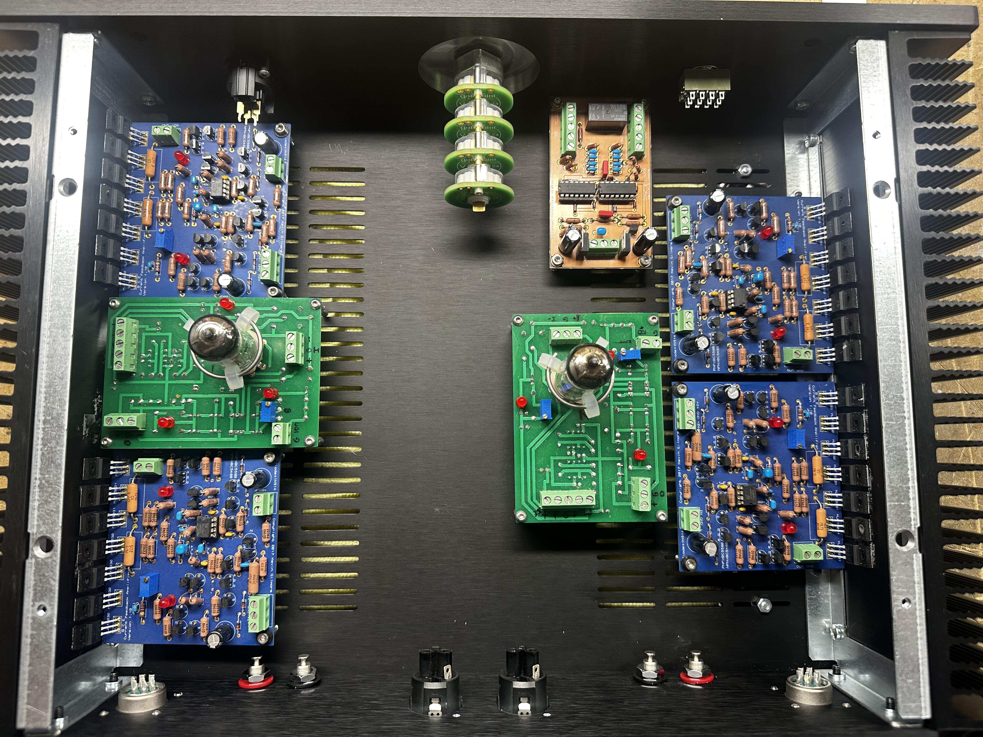
For reference, this design can take the E288CC (uber 6922 basically) with just minimal or no modifications. (Note they are 1/2" taller than a 6922) I had to slightly adjust the fixed cathode resistor value to get enough range out of the cathode trimpot, but that's about it. Dialed in to effectively zero offset/balance. A couple of the mirror transistors may get a bit warmer, but I found nothing alarmingly warm after many hours of use. It's controversial, and I'm quite a skeptic usually, but I found a significant improvement going from very nice but "normal" Amperex A-frame 6DJ8/ECC88 (essentially a 6922) to the Siemens E288CC. Got mine from Brent Jessee in Chicago. Detail, width, "3D". Tighter less boomy, but still very strong/punchy low end. My .02c
-
and now for something completely different part 3
Satyrnine replied to kevin gilmore's topic in Do It Yourself
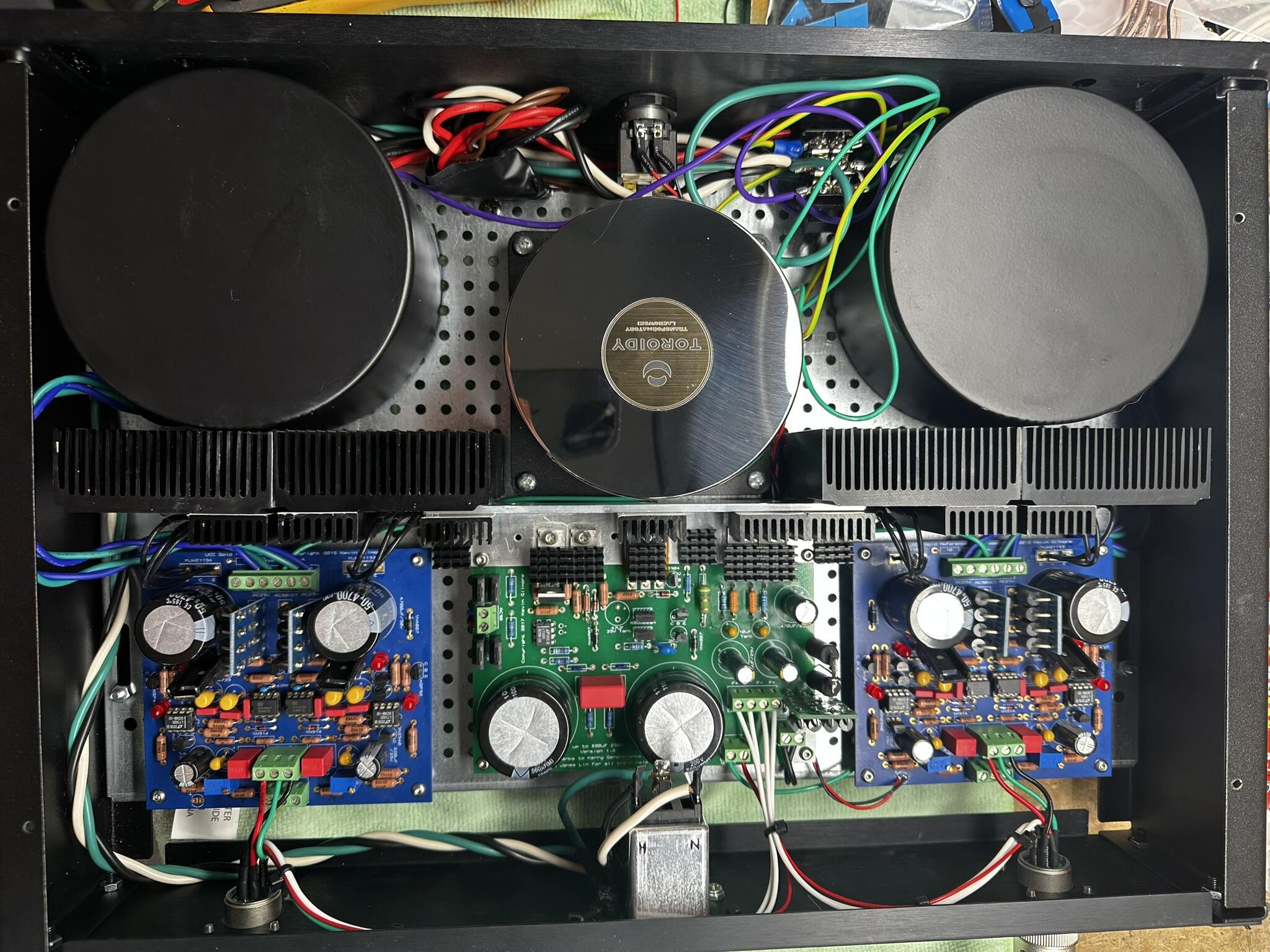
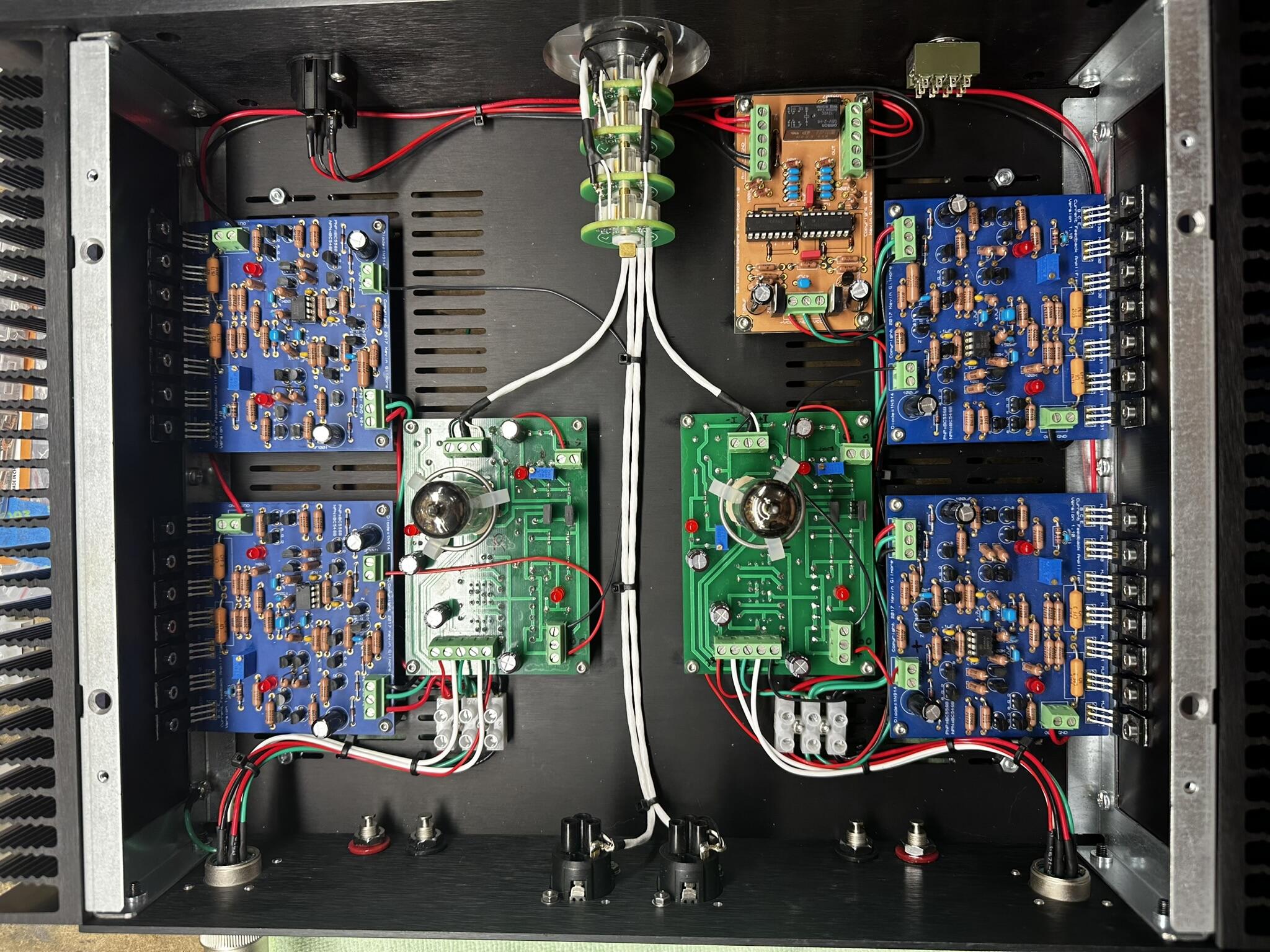
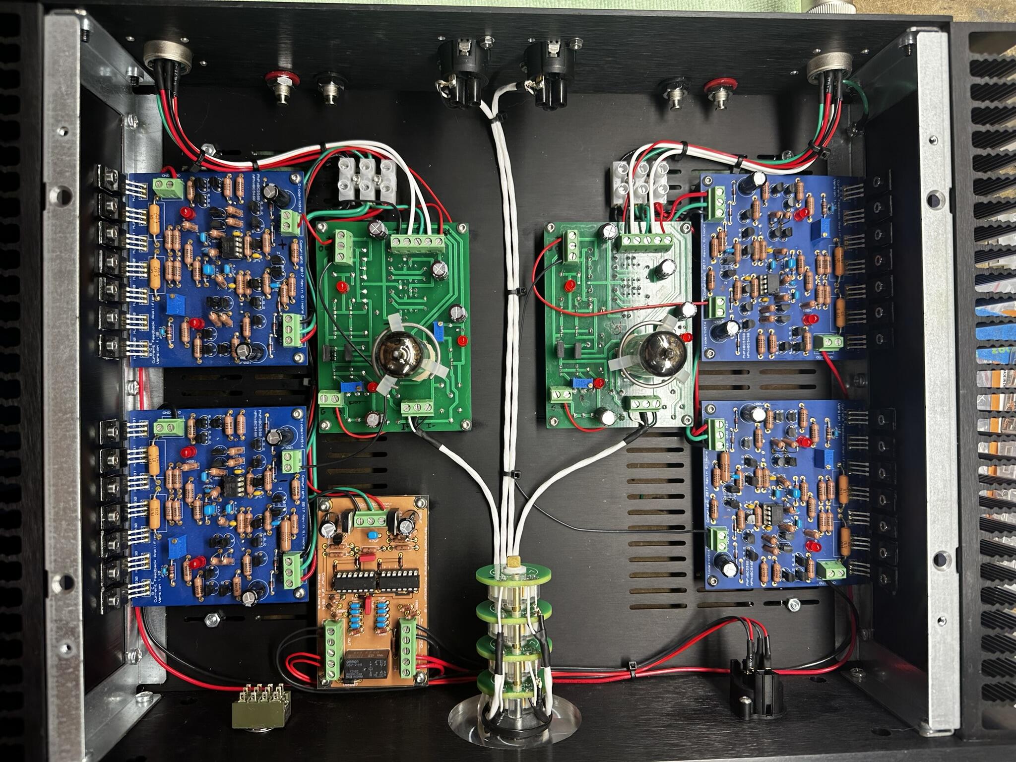
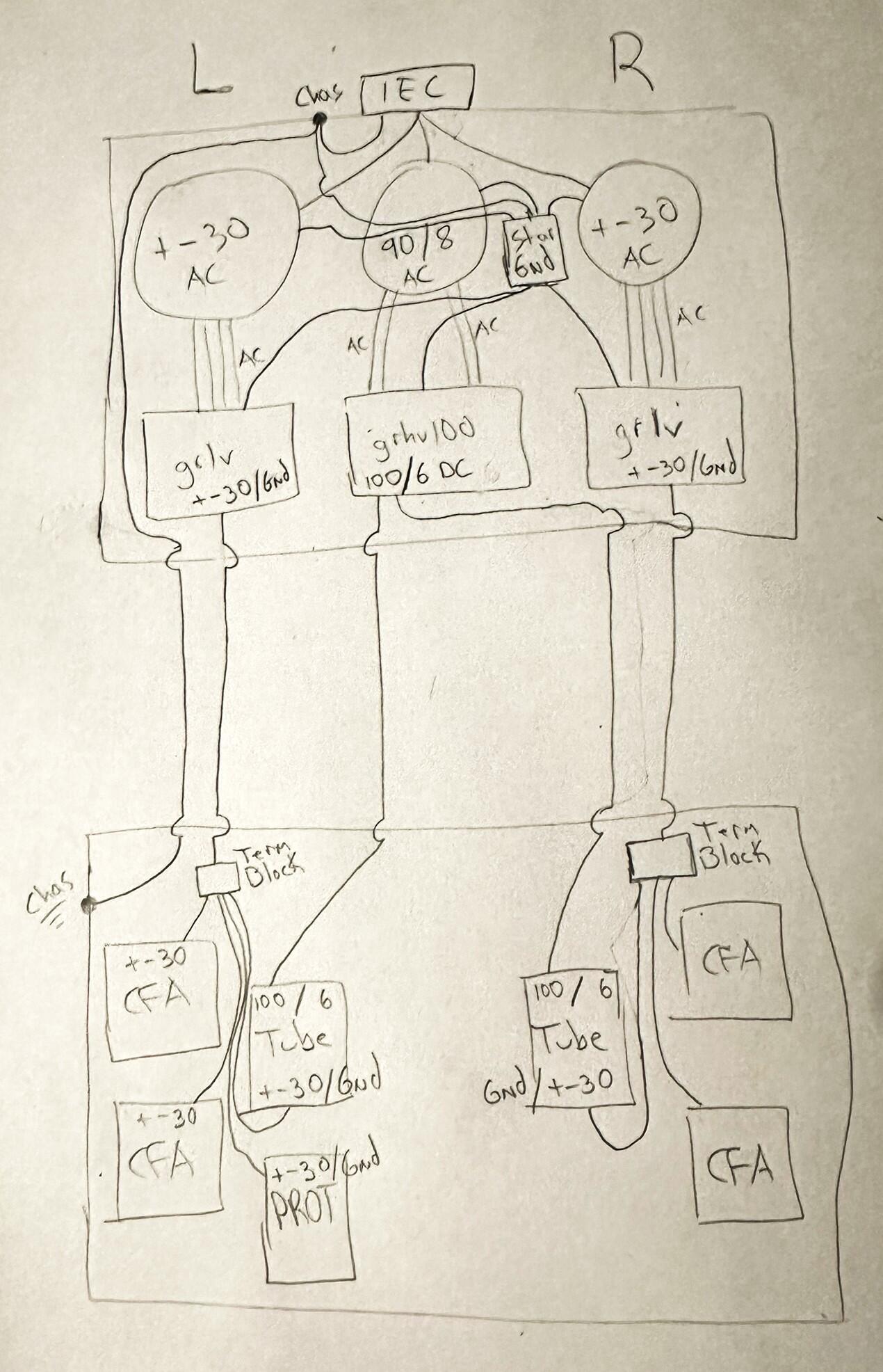
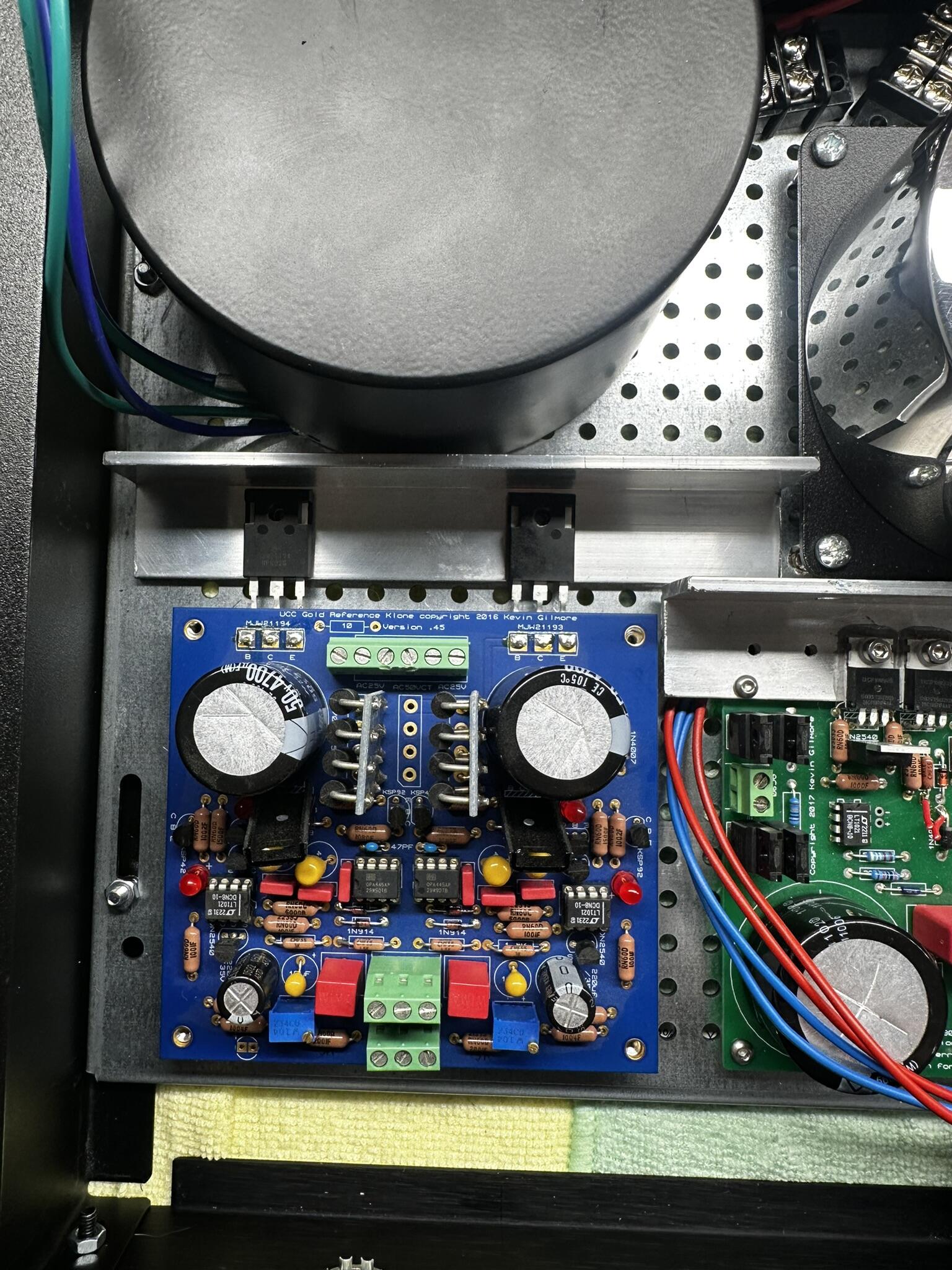
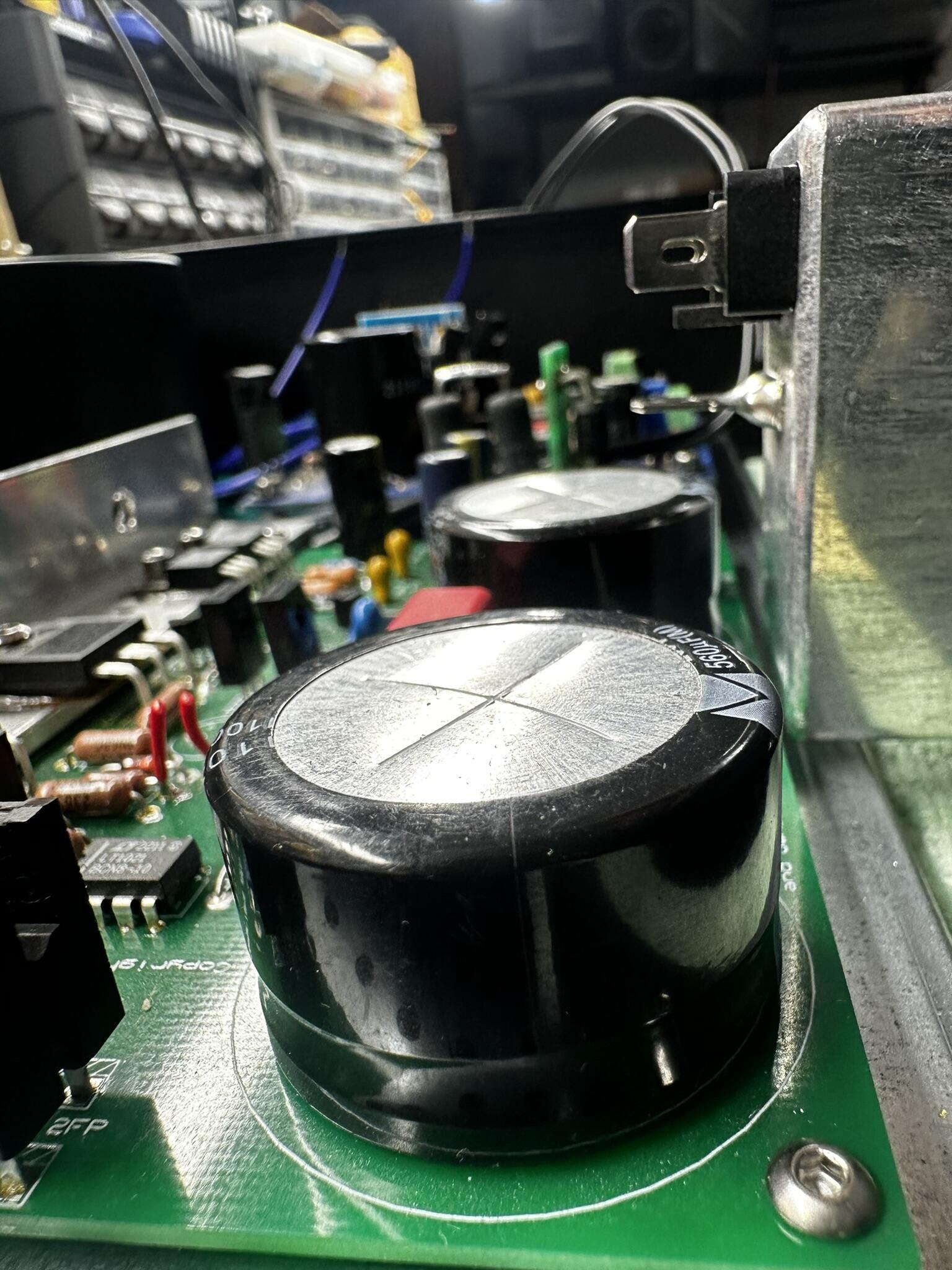
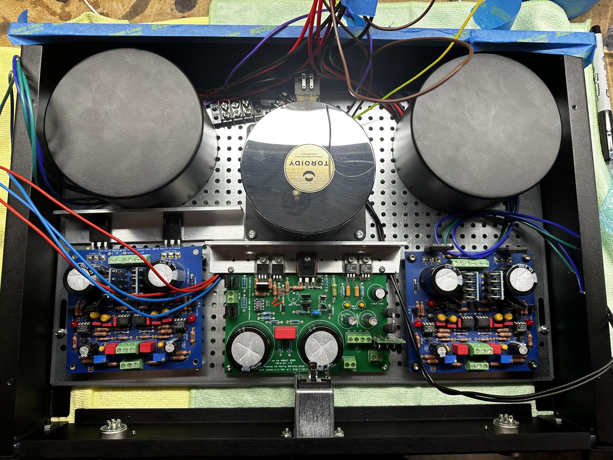
Protector board noise... I still have noise on whichever "side" (dual mono) I connect the protector board power to. If I use low sensitivity cans, like my HE6SE, I can't hear anything, but high sensitivity cans, like my LCD-X, there is still a persistent and annoying very high frequency noise. I'm more and more sure the protector board is causing it. I'm currently running no shield at all from outputs to headphones, just 4 wires. I've tried connecting the protector board ground to the star ground as well as "chassis". No change. At this point I think I need a separate supply all together, or possibly a RC filter between the grlv and protector board, to both filter and drop the 30v down closer to 12v a bit. Bad idea? EDIT: I added 1k resistors on the +30v and -30v inputs. Noise is gone! Getting about 13v on the + input after the added 1k, before the regulator, and about 25v on the - input. Everything seems to be functioning properly, looks like that did it, unless anyone can think of a reason this is a bad idea? Here's the wiring scheme and pics. Messy wiring at top by transformers is temporary, waiting on a proper dist block. And no, my speaker jacks are wired yet, my headphone/speakers switch is just a smidge too short to allow a nut on the inside, so I can't tighten it down. Prob going to 3d print a bracket of some sort to hold it. All wire is silver plated copper/teflon, not that it prob makes any difference.
-
Alright, the vast majority of my noise issue is resolved, but I still have noise on whichever "side" I connect the protector board power to. If I use low sensitivity cans, like my HE6SE, I can't hear anything, but high sensitivity cans, like my LCD-X, there is still a persistent and annoying very high frequency noise. I'm more and more sure the protector board is causing it. I'm currently running no shield at all from outputs to headphones, just 4 wires. I've tried connecting the protector board ground to the star ground as well as "chassis". No change. At this point I think I need a separate supply all together, or possibly a RC filter between the grlv and protector board, to both filter and drop the 30v down closer to 12v a bit. Bad idea? EDIT: I added 1k resistors on the +30v and -30v inputs. Noise is gone! Getting about 13v on the + input after the added 1k, before the regulator, and about 25v on the - input. Probably only needed the resistor on the + side that drives the relay, but can't hurt I guess. Everything seems to be functioning properly, looks like that did it, unless anyone can think of a reason this is a bad idea? If anyone else has this problem with 30v rails, give it a shot! Here's the wiring scheme and pics.
-
and now for something completely different part 3
Satyrnine replied to kevin gilmore's topic in Do It Yourself
Nice cans! I just nabbed a pair of HE6SEs, but also have LCD-2 and LCD-X. I surely won't be driving anything large with the CFA, just some small, efficient near field monitors on my desk, supported with a powered sub. Dukei said that his customers had good things to say about it with small nearfield speakers. We'll see I guess. I def have other amps if it doesn't work out. (various modded adcoms, GFA-535, 545, and 555) This build is taking it's toll, sooooo much work, although I'm admittedly chose hard mode with the dual mono, dual chassis, tube input version. -
and now for something completely different part 3
Satyrnine replied to kevin gilmore's topic in Do It Yourself
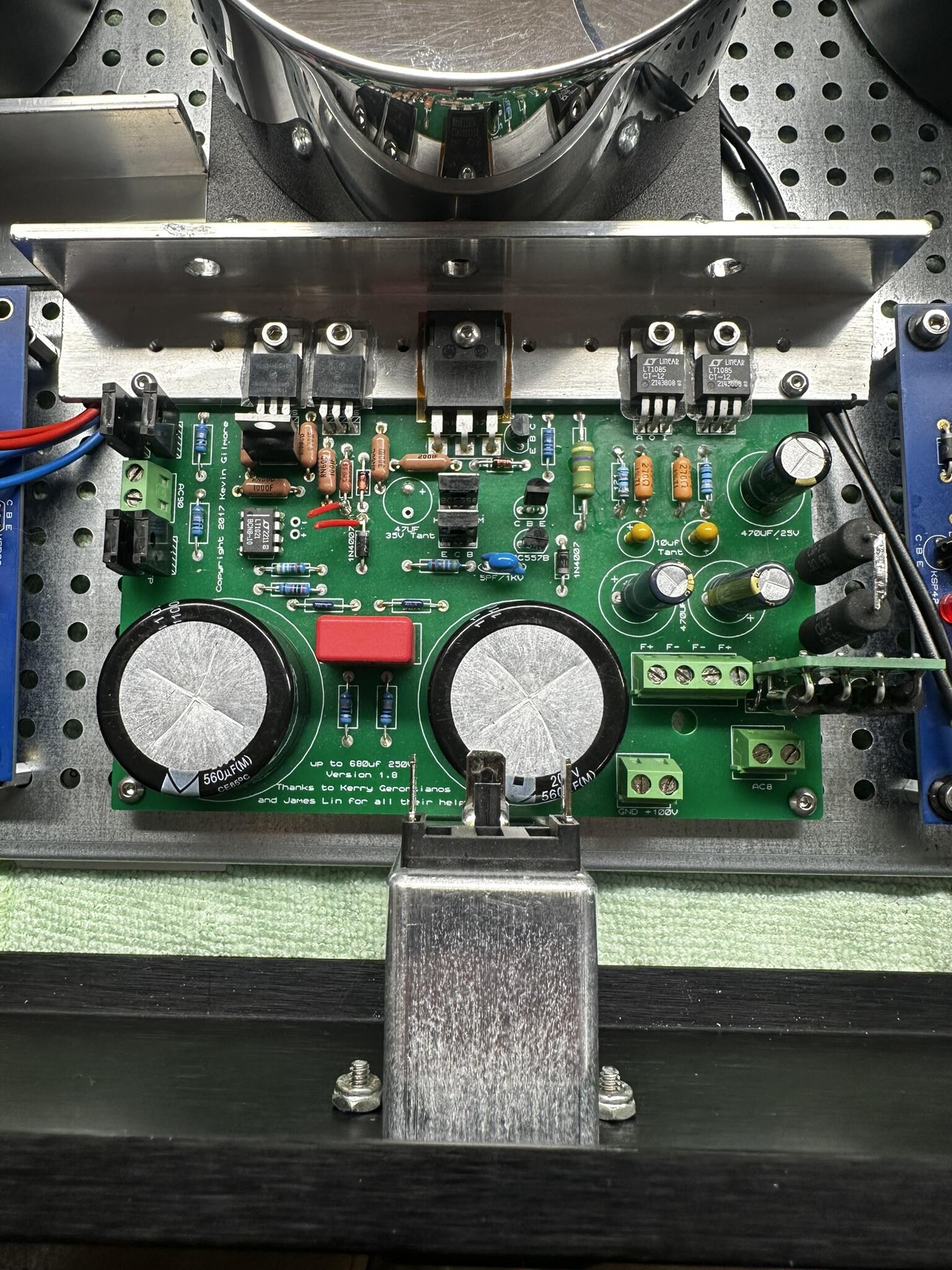
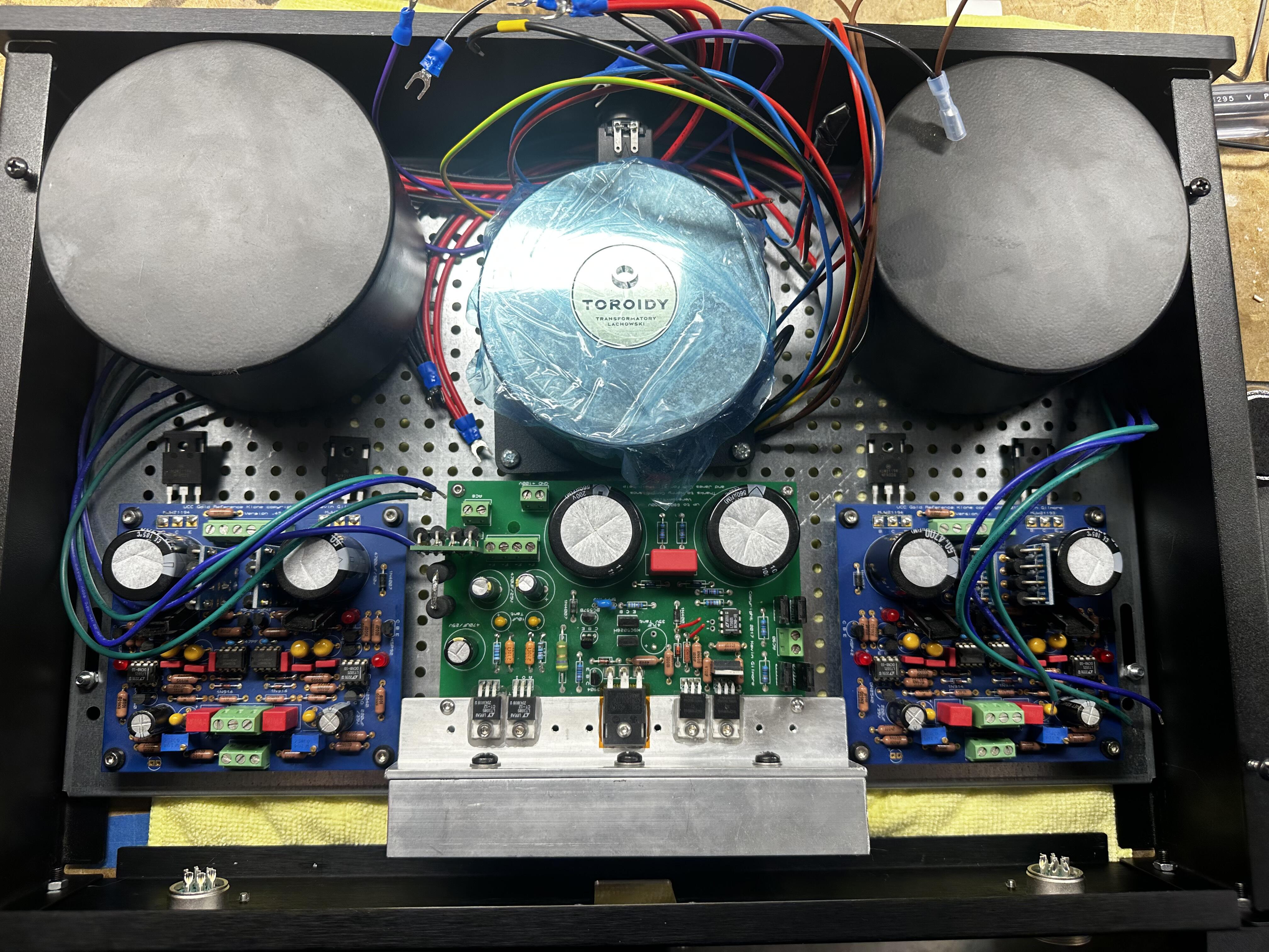
Thanks Pars! I’ll give that configuration a look! Are you driving speakers or just headphones with the dynafet? Weird that mine were running so cool, even with a susvara. As for the bridge boards, It must be because we have different bridge boards, as these have running great for quite a while, just finally stuffing it all into the chassis. Early on I actually put my bridge boards in like yours and got no output on one side because of it, so must be a board difference. Good eye! Side question: what value are you using for main filter caps on your grlv’s? They look large. I was contemplating if I could benefit from bigger caps on mine, I have plenty of vertical space. I also see some putting larger local filter caps on each cfa board. Thank You! Happy Holidays! -
and now for something completely different part 3
Satyrnine replied to kevin gilmore's topic in Do It Yourself
Hi Pars, could you (or anyone!) elaborate on the extra heatsinking for the grlvs? I admittedly have only tested with 50-600ohm headphone loads, but the small sinks I had on the grlv's then barely got warm at all. Maybe 105*F max. I have 100VA 30v transformers. I seem to recall someone mentioning that big transformers (and the 30vac secondaries) mean less reg heat from the grlvs? Below is what I was thinking of doing. I could also rotate them 90* left, bolting the L bracket to the side plate but that's even thinner steel than the bottom plate, and would move the DC outputs closer to the 90vac input on the grhv to it's right. I could also rotate the grlv 180* and remote mount the regs to the ~1.5mm aluminum back plate, but that would bring the grlv 30vac inputs closer to the DC jacks as well. Second, here's what I can get away with for IEC - grhv proximity. Think it will be a problem? It would give me enough room for the power switch at the top, plus room for distribution blocks for mains/grounds. Big thanks to anyone willing to share their wisdom.
-
and now for something completely different part 3
Satyrnine replied to kevin gilmore's topic in Do It Yourself
Hi Pars, Maybe I need to find a new power switch. This one sticks out about 1.5”. That’d let me shift everything back. I could also remote-mount the grlv regs to side panels with an added alum/copper bar. The lv transformers are 100VA Antek About the phoenix blocks, I think I may agree with you. The amount of times these became loose on me makes one question their reliability. -
and now for something completely different part 3
Satyrnine replied to kevin gilmore's topic in Do It Yourself
Can anyone offer their input on my layout before I start drilling? Amp: Left or right layout? Input comes in the middle, so figured I'd go right down the middle to the vol pot. DC comes in on each side. Which layout is best? Power Supply: The center transformer will interfere with the rather deep power switch if I push it back any further. Too close to the GRHV100 board? Is the GRHV too close to IEC input at the rear/bottom? Note the heatsink on the GRHV won't be there, sand will be sinked to bottom plate via a block I think. Flip position of GRHV? Thanks!
-
and now for something completely different part 3
Satyrnine replied to kevin gilmore's topic in Do It Yourself
I surely am using balanced headphones and balanced speaker outs. The issue just lies in that the speaker level inputs on most subs have negative terminals that are common, which would pop the cfa3 -outs if wired traditionally. Maybe that question was more aimed towards Pars' comment on how Kerry wires SE headphones to a differential amp, and not me specifically, but thought I'd clarify. Thanks! -
and now for something completely different part 3
Satyrnine replied to kevin gilmore's topic in Do It Yourself
Thanks Guys! I’ll give it a shot! -
and now for something completely different part 3
Satyrnine replied to kevin gilmore's topic in Do It Yourself
Sorry if I mis-wrote. The sub is a powered sub, the speaker level inputs are just a way to get signal to it. Said speaker level inputs have an opamp buffer/mixer to combine the L and R signals and feed it to the built-in plate amp of the sub. So the CFA should see no load from the speaker level inputs on the sub. This method is how REL tells customers to connect their powered subs to a differential amp. According to them the only necessary connections are the L+ and R+. They suggest the cfa chassis to sub high level - connection “if there is hum”. https://rel.net/blog/2015-07-23/how-to/how-to-connect-a-rel-to-a-balanced-amp/ -
and now for something completely different part 3
Satyrnine replied to kevin gilmore's topic in Do It Yourself
Can anyone verify this is the proper way to connect a subwoofer with speaker level inputs to a differential amp like the CFA3: CFA3 > SUB R+ > R+ SPK LVL IN L+ > L+ SPK LVL IN Chassis > R- and L- SPK LVL IN I'm excited to use the CFA3 with high efficiency monitors, but with "only" 15W/chan will definitely want a small sub. Sub is a small velodyne. -
and now for something completely different part 3
Satyrnine replied to kevin gilmore's topic in Do It Yourself
Good idea! I was planning on using a nibbler to just cut a notch in the lips, which should look decent, but a spacer would definitely work too. -
and now for something completely different part 3
Satyrnine replied to kevin gilmore's topic in Do It Yourself
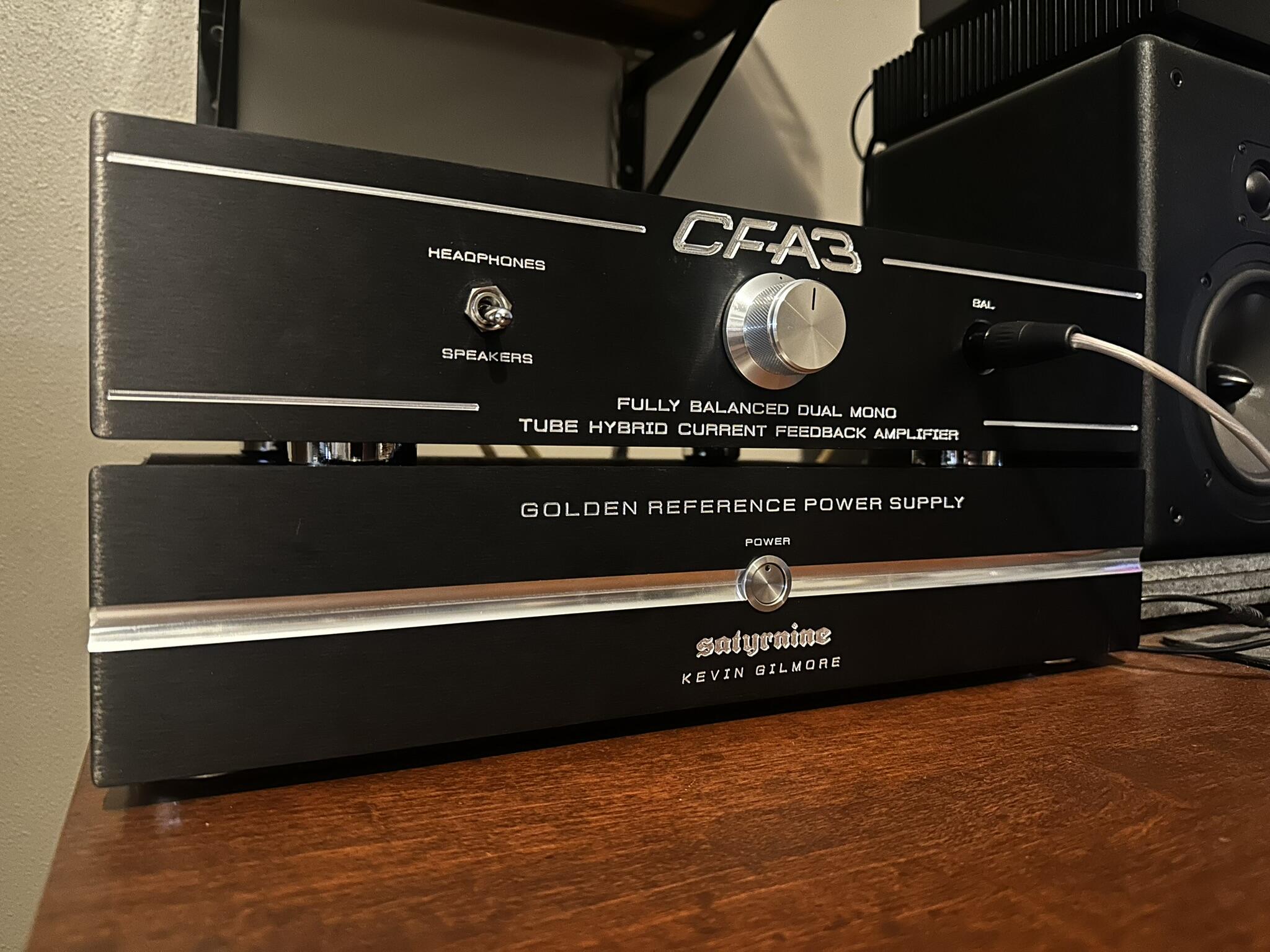
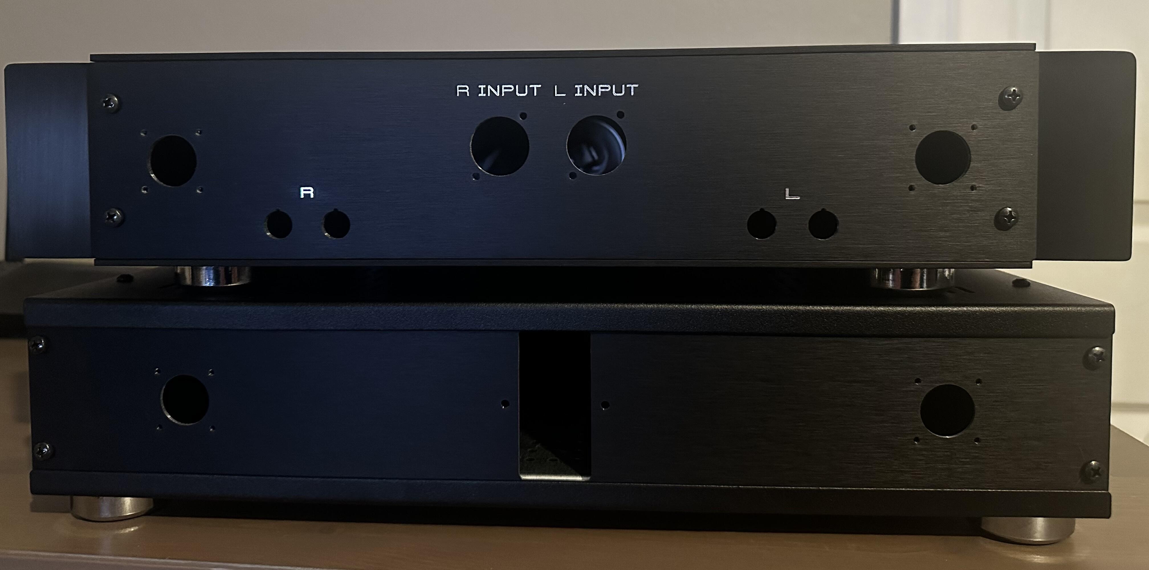
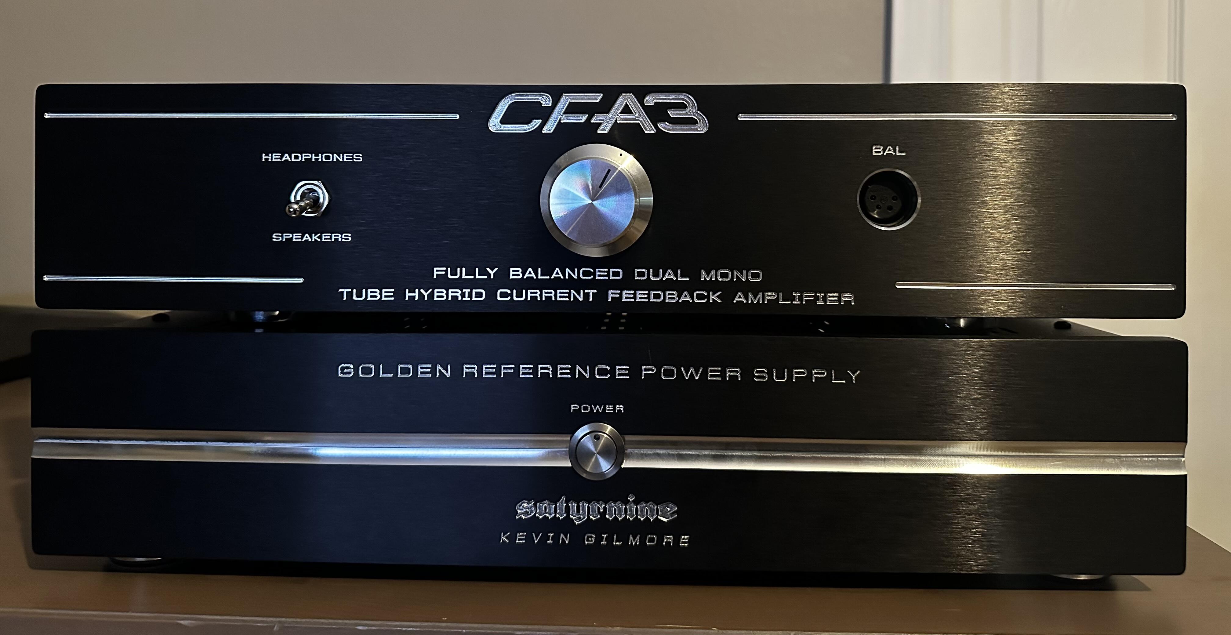
Chassis Mocked up. Still mostly empty. Definitely will need to trim the lips of the top and bottom plates of the PSU chassis to fit the IEC block's trim, but otherwise extremely happy. Not sure if I've mentioned but this is just a one-off for personal use. Definitely a huge setup, and doesn't come close to the refinement of many of your amazing builds, but for the first headphone amp I've built from scratch, (RIGHT to the deep end, haha!) I'm pretty content so far. haha! Not pictured, JAE DC connectors, Neutrik XLR inputs, CMC Rhodium 5-ways.
-
Could anyone offer a starting point to lengthen delay? First 100k to 200k too big of a jump?
-
Yep, apparently. Didn't think just a floating shield could do that... Thank you for all of your help here and elsewhere, I seriously appreciate it!
-
Well, right as I was about to give up and buy a pre-made board I figured my issue out. 4P XLR shield shouldn't be connected to protector board gnd apparently? If I disconnect the ground between 4pin XLR jack shield and the protector board, no noise. Also no noise if I ground the 4P XLR connector shield to star ground. Protector board itself is also connected to star ground of course. So, ground loop/shared ground return current issue? Sure was a high pitched noise... What gave me the idea to try this was when I touched the barrel of the XLR jack, the noise lessened and then slowly went completely away. Let go, noise came back. That told me "ground issue" and here we are. Fixed.
-
and now for something completely different part 3
Satyrnine replied to kevin gilmore's topic in Do It Yourself
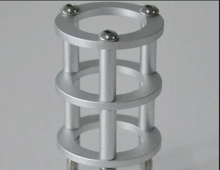
I got lucky with them, usually they charge if you don't supply CNC files directly. I made vector drawings to-scale, but don't know solidworks or such, so they definitely had to do some conversion and recreation to some degree, but I didn't get charged for the additional file creation fee. Gianluca and I went back and forth probably 50+ times over a number of months. Definitely great to work with, and like you mentioned, easily cheaper than sourcing locally or taking a risk with aliexpress/etc. If anyone with a CFA hasn't tried the ubal2baltube boards, they add just the right amount of "tube" flavor, and still keeps the CFA detail/slam. I splurged on nice Siemens E288CC tubes (not quite the same as a 6922, double heater and plate current) which meant some additional tweaking of the tube boards, but I think it was worth it. Compared to basic EH 6922 they are a clear improvement. They ARE a bit taller than a 6922 though, so they may end up sticking out the top of the chassis, we'll see, ha! Could look pretty neat with some tube cages, and make swapping easier. Like this:
-
and now for something completely different part 3
Satyrnine replied to kevin gilmore's topic in Do It Yourself
About $650 shipped, with all the customizations and upgraded alum top/rear panels and 10mm front panels. Rear panels are machined and labeled as well. Pricey, but fair I think, I wanted to go all-out. The tube input boards are fantastic sounding. -
and now for something completely different part 3
Satyrnine replied to kevin gilmore's topic in Do It Yourself
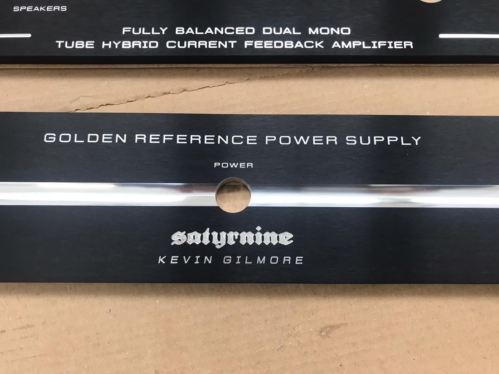
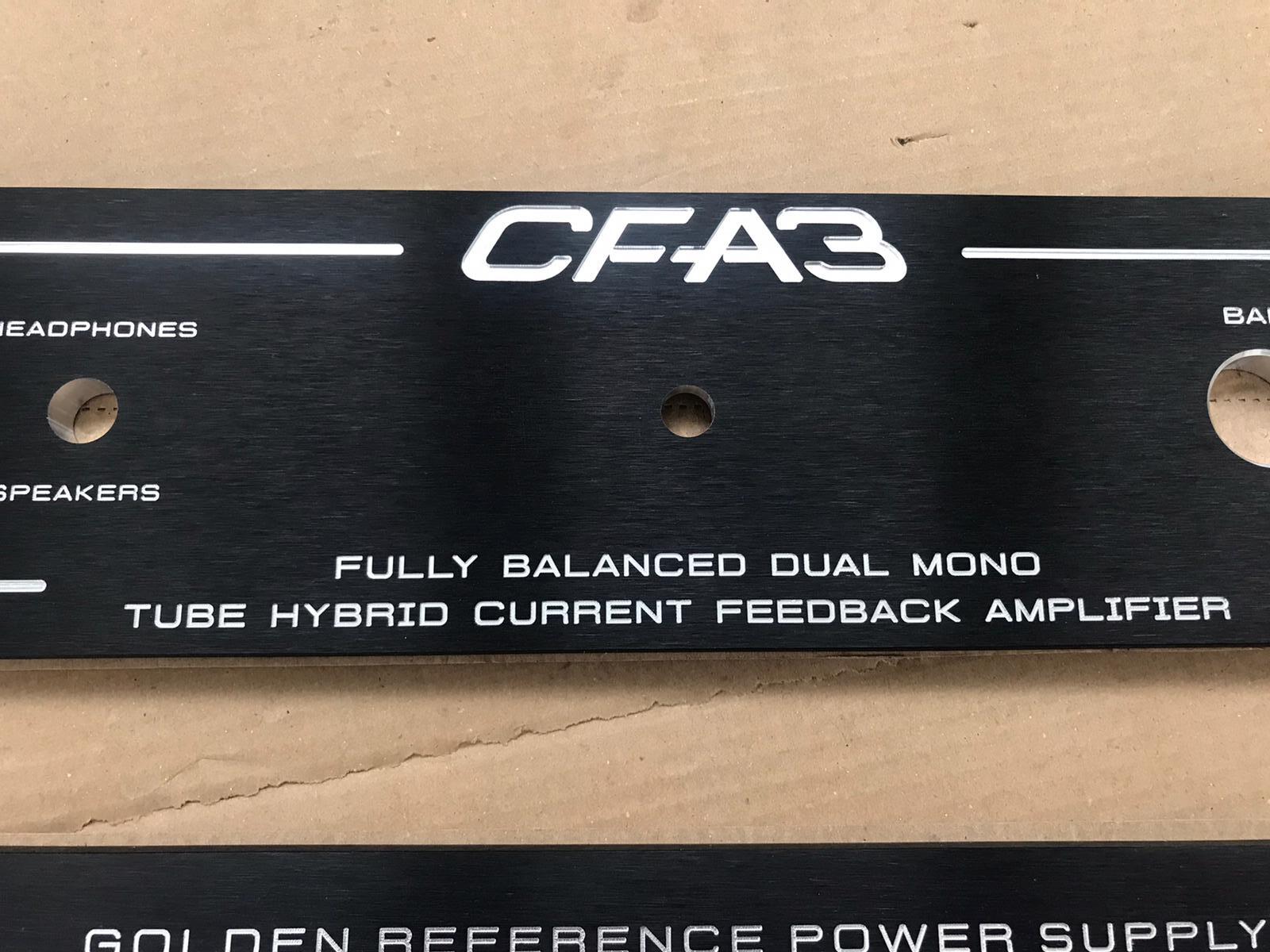
Just wanted to share a sneak peak of the machined panels for my split chassis tube input CFA3. Just got pics from modushop. 10mm thick. Very pleased with how they turned out! Will be 1x 2U Dissipante and 1x 2U Pessante. Gianluca was amazing to work with, top notch customer service.