


bobkatz
-
Posts
87 -
Joined
-
Last visited
Content Type
Profiles
Forums
Events
Posts posted by bobkatz
-
-
Thanks Kevin. Your contributions to the headphone and audio community are legendary! Your quote below, my reply above.
The reason why I felt the gain was too much was a combination of using a professional level source (which I can adjust, however) and a 1 dB/step attenuator that has to be optimized as it only has 24 steps. This amp has the two 500 K resistors to ground installed on the input side but it is not the HV model. The 500K resistors are included on your schematic at http://gilmore2.chem.northwestern.edu/projects/showfile.php?file=gilmore2_prj.htm.
Who knows how I got it to oscillate (it was painful but I had my hands on the pot, so it was momentary) and it was only with an open input and only the unbalanced input. I don't think I have any ground loops, but the unshielded twisted pair input cables are not that far from the outputs. Let's leave it, the additional input resistors have removed the oscillation (or, simply, plugging in any source) and it's not my concern.
As for the freq. response, it would be educational to see data. What do you think of my suggestion of removing the feedback and measuring the response at each stage in the currently-made unit (Justin says the only changes have been a couple of transistors)?
Thanks again,
Bob
The kgss was designed to european inputs which is .6 vrms input which makes 600 vrms output.
A gain of 60db. Or a voltage gain of 1000.
3 people in all of the last 10 years said that the gain was too low, and i told them how
to get an extra 6db by swapping resistors. One person said the gain was too high as he
listens very quietly and i told him how to change the input fet source resistors to
reduce the gain 10db.
Sounds like your professional source is way high in output voltage, something like 10vrms
and even with resistor changes, this would clip the input stage. So an input attenuator
is required.
With a shunt attenuator, and the attenuation at minimum, and no input load resistors
(depends on which of the many versions of circuit board you have) i'm sure its going
to oscillate. The 500k resistors on the new kgsshv board take care of that issue.
Not sure about the frequency response, i'm going to have to look up my data, i did not
have time to do that last night. If the lack of frequency response bothers you, you
certainly could build a T2 which is way flat to well over 100khz.
-
I can't imagine a situation where I'd want to have a max attenuation of only 24dB on any amp.
I've been running an optimized 1 dB/step monitor gain control in various rooms and studios around the house for about 8-10 years now. By optimized I mean that the monitor gain has been calibrated to produce 83 dB SPL with -20 dBFS RMS pink noise per channel. After optimizing the power amp gain this way, the control typically runs in a range of 4 to 6 dB around a -9 center, for the majority of music that's ever been recorded, and as high as 0 dB in rare cases (certain audiophile recordings) and as low as -16 dB in rare cases (certain egregiously-distorted and overmodulated hypercompressed recordings). The music can be made as loud as the most insensitive ears can take and as soft as anyone would wish. 24 steps are definitely enough if you optimize the gain structure versus SPL. This includes a range including surround reproduction of wide-range theatrical films (which can be made to sound annoyingly "too loud" at the top of the pot), stereo reproduction of audiophile material, stereo reproduction of well-recorded music, and stereo reproduction of hypercompressed material as hot as "Black Eyed Peas", or "Green Day", for example. Once the gain range has been optimized to this SPL, even the most sensitive listener on the planet will play Green Day at perhaps -18, which still leaves 6 dB at the bottom for extreme circumstances.
I once ran a TKD 1 dB/step attenuator with as many as 48 steps if I recall correctly, and never went below about -16 and found the rest of the steps to be unnecessary, once the gains were optimized. If they're not optimized, then you find the attenuator just runs in a different average position but still within a range of about 6 dB or less on an average day, or 16 dB on the extremes. If after this optimization, anyone who finds they need more than 24 dB max attenuation for normal music listening, AND can find music that they can tolerate near 0 dB on the same attenuator, then I swear they must be deaf.
I also have installed a dim switch on my KGSS to take care of phone calls or in-room conversation if you want the amp to be quiet. That's the only legitimate need for an extra low step below -24
 ). You could also make the last step be -40 instead of -24, but a dim switch is much faster, more convenient and more ergonomic. Conclusion: 24 1 dB steps are enough, when the system is optimized.
BK
-
forgot about that, KG's ancient pictures are too fuzzy to see if he snuck in any compensation caps
also, the 2SA1156 was changed to 2SA1486 because the 1156 was running too close to its 400V limit, though that was really more of an issue on the Blue Hawaii.
Hmmmm, we may be getting somewhere. Can KG take a measurement of the original circuit for reference (or, I assume, your original specs on the Headamp site referred to the original circuit). But you don't have any compensation caps, do you? We could spice this to the end of days, but if you want to measure first, and find which stage is the source of the rolloff, one way would be to remove the negative feedback and (very carefully) measure frequency response at each stage---with a DC isolated, battery-operated voltmeter with adequate bandwidth. Not being very familiar with the fancy current mode topology, I'm not sure 100% if this is the correct procedure. It may be over my head.
BK
-
I would say the HF roll-off is a combination of the two, and frankly I'm pretty sure the O2MK2 rolls off faster than ~1.5dB at 20kHZ.(I'm in the O2-is-dark camp) Nice job on the (thankfully) single pole filter though, I'm sure it helped.
Perhaps check the Stax thread for the bass port mod on the O2Mk2, it should help the boomy bass and clean up the midrange a tad.
Based on the exact EQ that I applied, and careful listening/comparing with my reference speakers, I would say the O2MK2 (on its own) is no more than -2.5 at 20 kHz, subject to personal taste. Combine that with my measured response of my KGSS before EQ, I'd say that's a deadly combination. I'm not currently tempted to boost my amp beyond its current flat state, it sounds good. However, bright recordings are not excessively bright, and I could see another listener tilting it up another 1/2 to 1 dB at 20K depending on personal taste. This will also change if I do the port mod.
BK
-
Bob,
Did you measure the FR after lowering the gain? i would guess variations in the FR from KG's original amp, which was built at least a decade ago, would be due to changes in open loop gain from use of slightly different transistors, or slightly different voltages of the LEDs
Yes, I did.
Makes sense. Justin, can you measure the frequency response of the next amp you build (be sure to test at various potentiometer settings to see if it's affected by the pot). It would be useful for Kevin to step in and talk about this. No one (least of all me) is upset about this turn of events. To repeat, I'm happy with this amplifier! I found a problem, made a solution and perhaps an even better solution can be found.
Here's the exact order of events:
1) I listened and found the amp to have excessive gain, especially for use with 24-step 1 dB/step pots. I was running too close to the bottom of the steppers. At this point I did not listen too carefully to the sound as I did not have good range on the pots.
2) I did NOT measure the response of the amp at this time. I immediately installed the 15 dB attenuator circuit, consisting of two 20K and 1 10 K resistor in a balanced U pad attached directly to the input terminals at the PC board. (Justin, this replaced the 200 Ohm resistors you had installed).
3) I listened, and detected a loss in the high end while listening.
4) I attributed the problems to the reknowned issue with the Stax O2 Mk2. It seemed logical.
5) I designed a circuit to boost the high end to compensate for the perceived loss.
6) Before installing the EQ circuit, I took a baseline frequency response measurement of the amp. It was rolled off 1.6 dB at 20 kHz compared to 1 kHz. Solution: I should attack the amp problem first, before the phones! I redesigned the EQ to exactly compensate for the measured loss.
7) I installed the EQ circuit and remeasured was happy to discover it made the amp flat to within 0.1 dB from 20 Hz to 20 kHz.
 I listened! I'm a happy camper. (Well, would be nice to tame the below 60 Hz resonance of the Stax, but it's a pleasant sound nevertheless, will investigate the port mod).
 -
I am pretty sure that the OP's "excessive gain" comment comes from the fact that he is using a stepper with 1db steps=24db of range. Nobody notices that they have too much gain when their volume controls are set to -39db 24db+15db=39db
 Considering that he only needed to knock off another 15db id say the gain is pretty well set.
 Why not change the gain with the feedback resistors?
I am curious which inputs were used to test. I mean SE or balanced? I have seen the frequency response described in SIMULATIONS of the BH using SE inputs. I know, I know, its a weak comparison but the topology of the input stage and how feedback is applied are similar.
I used the balanced inputs for my listening and measurements. The way I have it set, the unbalanced inputs simply ground the low side of the line going to the selector switch which then goes into the balanced Goldpoint attenuator.
As for the feedback resistor, I'd rather leave Kevin's judgment of how much negative feedback he wants. Good description of what's going on with the stepper pot. To emphasize, holding your attenuators at -39 dB for normal playback seems to me to be a dangerous condition. You could easily blow your ears out by accident! I've got sufficient output level from the DAC to need to hold the attenuator anywhere from about -16 through -3 dB for an extremely wide range of playback sources and music, with the average of good sources falling at about -9 dB on the attenuator. That's an optimum but not excessive setting for me.
-
I've never heard about any issues with excessive gain on the KGSS. It is in the same ballpark as the Stax amps and the pot is always in the 11 to 1 o'clock position for me.
As for the FR response of the amp, you are really starting on the wrong end since the SR-007Mk2 is the culprit here. They are very non linear but read the last few pages of the Stax thread about how you can fix that.
Let's face it, Spritzer, you like to listen loud. ;-). We could get into measurements of input level versus SPL, etc., but it's not important. I strongly feel the KGSS has excessive gain with U.S. or Professional level outputs. Either way we can agree to disagree on that. And clearly, for those who wish to try the Katz "eq mod", you have to attenuate to create the RC network. As for whether the problem with the Stax is due to the Stax or the KGSS (or the particular KGSS that I have) why not say that it can be due to both! If the amp does not measure flat, that is a problem and as far as I'm concerned the first place to tackle any perception of HF loss. We all need one or two of you to please carefully measure and either confirm or refute my measurements before I/we do further investigation. As an experienced audio engineer I know how to measure frequency response and I would not have posted if I was not 100% sure of my measurements. The only thing I did not do was measure frequency response at the input terminals to see if there is a loss in the cabling or a capacitive rolloff due to the input impedances involved.
The bass issue intrigues me! I did read about the port mod but concluded that people were saying the port was to fix the "Stax Fart" and it looked to me that sealing the port was not to alleviate any sonic disorders. I'll certainly investigate and try the port mod when I get a chance. I'm quite worried about the procedure to put the earpads back due to that spring, never having tried opening these phones. Does anyone have a link to the instructions for earpad takeapart? Will Mortite work to seal this port? http://www.amazon.com/Frost-B2-Mortite-Caulking-19-ounce/dp/B000LNODSQ
Thanks, all,
Bob
-
isn't this the part when you complain that Justin's specs of 5Hz-45KHz +/-0.1dB aren't accurate and demand your money back? I guess that's more HF, but if you post it over there be sure to update us with the ensuing reaction.
Post it over "there"? Where's "there"? I did alert Justin to this post by email. I'm very happy with this amp, and basically I'm curious what mechanism is causing the non-flat response. It would be a perfect complement to Lambas, for example. But I know that Kevin designed it for use with O2s. Can some of you who are capable please measure the frequency response of your units? I've not seen a frequency response or distortion spec anywhere, to be honest. But again, this is not an issue. It's an immaculately-designed PC board and circuit, and who knows, maybe the "Katz mod" will become a standard
).BK
-
Schematics and photos attached!
I got my belated Christmas present from Justin the other day, a lovely KGSS amp. Finally I got to hear my new Stax 007 Mk2 (Omega 2) in all their glory. Knowing that I was going to install my own Goldpoint 1 dB/step attenuators, and a Left to mono switch (to check headphone balance), I asked Justin to agree to construct a KGSS without wiring the input connections to the back panel or installing a volume control (yes, he did test and burn in the board). Leaving me with some fun to do on my own! The first thing I discovered is that the KGSS is extremely sensitive. I judged it has at least 15 dB too much extra gain, even with consumer (nominal -10 dBu) sources. Without an additional attenuator, I even found it easy to incite HF oscillation by opening my Goldpoints fully, with an open unbalanced input. This is not a good idea! So I designed an additional 15 dB attenuator circuit, installed it at the KGSS input. Then I proceeded to listen to a wide variety of reference material through my Benchmark DAC-1. This includes much of my own material which I have mastered and which I know intimately monitored through the Revel loudspeakers in my mastering room. To be honest, I was disappointed with the high end, it was just not open enough nor did the "air" frequencies come close to that of my Revels. Others have reported the Omega 2's to be a little "dark" or closed in and I was prepared for that. This is partly due to the extended bass response of these wonderful headphones, which may be as much as 1 dB too much below about 60 Hz.
So, I decided to design a simple passive equalizer to compensate for the Stax response. This took advantage of the 15 dB pad I had already installed. I figured I might need between 1/2 and 1 dB rise from 10K to 20K, and in Spice I designed the filter. Then I went to the bench, and proceeded to make a baseline frequency response measurement before installing the EQ (which consists of two added capacitors per channel, one on each phase of the balanced line). Much to my dismay, I discovered that this KGSS is rolled off. Flat at 1 kHz, it was -.13 dB down at 5k, -.48 dB down at 10k, -1.1 dB down at 16K, and -1.61 dB down at 20kHz!!! This was the explanation for the loss of air and high end, not the Stax phones at all. I measured this rolloff at the headphone outputs, the same rolloff whether balanced or single ended (relative to ground). I made measurements at various gains and pot positions, and nothing significant changed. Left and right channel measured identically (the same rolloff) within 0.1 dB. I conclude that some internal capacitive losses are occurring, despite Kevin's current-mode circuit. Or some unknown. Clearly, whatever is causing the rolloff is fully symmetrical as the plus and minus outputs of both channels measure identically. It sure sounds like the rollof is within the amp itself. I think that Spritzer has been working on a new version of the KGSS, and I'd like to ask him to perform frequency response measurements on a stock unit and a new or modified unit and report here. I leave the possibility of capacitive losses in my input wiring, but it's doubtful, considering the cable lengths and positions of the resistors. I should have measured the response at the input terminals before I installed the amp in the mastering room, but that is not possible without too much effort on my part. I will do that measurement if someone else reports flat response with his KGSS.
There was full agreement in response between my high-end Fluke meter, my Audio Toolbox, and a classic Ballantine TVM, so it's not my measurement equipment, and I DID measure the test oscillator in the Audio Toolbox with the same tools, and I compensated for the generator's own slight irregularity (it has to be turned down +0.5 dB at 20kHz, but not at 16 kHz and below, strangely).
I am pleased to report that after the installation of the EQ mod, the amp is flat to less than 0.1 dB from 20 through 20 kHz, and it sounds marvelous now! So, what gives? Bottom line: I highly recommend this mod; the one-pole curve of the eq exactly mirrors the losses in the amp, and I no longer sense a loss of air or presence. I'm a happy camper now! I can give anyone who wishes a spreadsheet or fixed calculations for the 1 dB/step attenuator if you wish. Note that the Goldpoint wafer is normally designed for a ladder attenuator, but I didn't like the idea of sending the signal through all those resistors in series, so I designed it as a fixed series resistor with a switched single variable resistor. It's a fully-balanced variable U pad.


-
Justin at Headamp. Anyone had any recent successful dealings with Justin these past few months?
-
Yup. I had to add the 120V wires to the transformer and clear out some excess solder but it is pretty easy, at least on the unit I had
Spritzer, you didn't actually add new coils to the transformer, right? You just found the stubs of the coils which are intended for 120 volt use that they cut off in Japan, and hooked into them, right?
-
Nope, the OII (SR-007) construction is sturdier.
You make me feel much better!
Bob
-
Spritzer, does this apply to the Omega II as well?
BK
That's enough about those inferior dynamics!!!
So I've been working on this SR-Omega that needed some TLC. I don't think I've ever posted pics of an empty SR-Omega shell to show why I sometimes call them the tin cans...

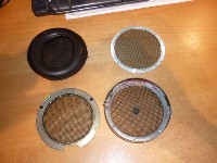
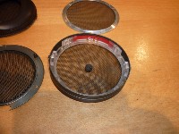
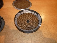

As you can see the cups are very thin and it is mostly just plastic in there. Couple that to the huge driver and no wonder they get a bit ill tempered at higher volume levels. Far cry from the SR-007 design where the drivers are securely mounted in a large slab of metal. Another insteresting bit is that Stax grounded the metal enclosure through large resistors to the + and - terminals.
-
Hello bobkatz,
Yes, we are talking about the same part of the schematic.
But... after the resistor R403 (4.7M) you find the capacitor C417 (0.1uF). After that there is is direct line to the bias-pins on the headphone connectors.
So in effect: no series resistor. Just an additional RC-filter stage in the bias supply.
The schematic prior to s/n 1000 does not have this capacitor. And thus does indeed have a series resistor in the bias line.
Things can easily be corrected for s/n over 1000 by just adding a 4.7M (or an other large value that you happen to have lying around) between the bias wire and the connectors.
Best regards,
Jac
I see. I think that we are not exactly arguing about the concept of there being no ballast resistor, but rather there being an extra filter cap after the 4.7M ballast resistor. So let's say, for purposes of discussion, all the Stax amps contain this resistor, but not all of them have the extra cap. And so the discussion begins. What would be the SONIC EFFECTS of this capacitor being there or not being there? It does "regulate" the bias voltage, but it also makes for a VERY slow charge up of the bias to the phones.
-
Hello, Quad. EDIT:
Pity I can no longer edit my post with the links to the manuals. Because the manuals are complete. Pages 13 and 14 are the pages which cover the modified schematics which include the protection diodes. I just didn't tape them together to make a large picture like I did with pages 11 and 12 (the original schematic version for older serial numbers).
Anyway, I see that in the newer schematic, I do see that R403 4.7 Meg is installed. Are we talking about different things? Perhaps someone rubbed this R out of your copy of the schematic
( -
Hello, Quad. I see that I did have enough of a portion of page 13 and did scan it to the service manual. In page 13, the "modified" Stax schematic for serial numbers that have the protection diodes, I do see that R403 4.7 Meg is installed. Are we talking about different things?
-
Hello bobkatz,
First of all: thank you for the manuals.
The notes on old manuals are always worthy of being read. Why invent the wheel twice?
You're welcome. It's fun looking at history, especially your own scribbled history in the margins of schematics.
So in fact you did implement a kind of balance control after all. Are they sonically of the same quality as the volume control or does that not make a difference?
Unfortunately they are not as good quality as the stepped volume control I built. Anything that has a wiper running against a resistive element will introduce more potential distortion than a wiper on a gold-contact switch. Maybe someday I'll build some switched rebalance attenuators for the SRA, but for now the SRA project is finished. Also, predicting attenuation to an exact portion of a decibel requires knowing the impedances and since the controls are in a passive part of the circuit and the balance control would be in series with the volume control, I cannot work out how I would be able to add an accurate stepped balance control in series with the stepped volume control without adding a buffer amp, which I do not want to do.
However, for the KGSS I already constructed two individual 1 dB/step volume controls which I hope solves both the volume and balance issue. But if 1 dB proves not to be enough I'll construct another Goldpoint-switch resistive balance control with 1/4 dB steps up to + or - 3 dB, IF I can work out the impedance issue and not add a buffer amp.
Sonically, it's all very subliminal and cumulative. Once I started listening to and building the best line-amp circuits for my various audio systems I became more of a purist than ever. Would I pass a blind test between a cermet trimmer and a gold-plated Vishay-loaded switch? Doubtful. But do I feel better having nice clean connections between input and output? Absolutely.I tend to feel that the sonic differences between volume controls are minimal. One of the main issues to me is very good tracking.
I also think that a good direct-connect DC servo amp sounds better than any capacitor, so I'm looking forward to my new KGSS when Justin gets it done. In a line driver amp, I have done the shootout between a superb DC servo amp and a superb audiophile grade coupling cap and the DC servo ate the cap for breakfast. So I'm a fan of direct coupling wherever possible.The output coupling caps: the listed voltage rating is probably just what Stax had at hand. Which indeed by no means implies a necessary value.
I expect that your output caps will sound similar to mine.
There is a school of thought that is against too high value capacitors. You could argue by using a largish value, you put a lot of (unnecessary?) dielectric material in the signal path. Which might have its own contribution to sound due to charge being kept in it.
Difficult to choose one way of thought of the other. I guess that the proof of the pudding is in the eating anyway.
I can't blame you. Take a look at Spritzer's enlightening post in this thread which covers both the cap issues and the diaphragm bias issues. It led me to believe that 300 volts is a reasonable value for normal bias phones as long as I don't play too loud (which I do not):About the 300V diaphragm bias: I am just too chicken to bias all my phones to a value which is much higher than recommended.
http://www.head-case.org/forums/headphones/785-headcase-stax-thread-342.html#post379470
That's very surprising. I've lost that part of the page of my service manual and it's not in my PDF which I just posted. But it shocks me (literally) to think of building a headphone amp without a large series resistor, at least as shock protection (current limiting) for the user. If I were Stax, I'd hate to be the focus of a wrongful death suit. You don't want lethal current-capable voltages coming out of a headphone socket. Anyway, it seems that all standardized electrostatic headphone biasing circuits I've seen include that series resistor as a standard.The bias series resistor is definitely not part of all Stax amps. F.e. see the service manual of the SRA-12S for s/n over1001.
Just shocks me! Can you point me to a copy of that schematic, please?C417 is directly across the bias output, and they did not put a series resistor in that line.
And as you described, the potential solution where you can solve both problems (for balanced circuits) include using a very small bypass capacitor between pin 1 and chassis. I believe there is a Neutrik 3 pin connector with an integral capacitor for this purposes. The RF rejection though, becomes nill at extreme frequencies unless you integrate this capacitor expertly.Concerning EMI and RFI: for high frequencies the current idea (in contrast to early thoughts) is indeed to groud as much as possible. Connect all connectors and screenings directly to ground.
For LF however, induction of flux from the mains or a nearby mains transformer quite easily induces a 50/60/100/120 Hz hum component in a ground circuit.
I hate debugging hum problems!
-
Hello, Quad and fellows. How do I get to be a high roller
).Anyway, first things first, my assistant carefully scanned the SRA-12S operating and service manuals and I have put them publicly on my dropbox as PDFs!
So, here they are the links:
http://dl.dropbox.com/u/9188783/Stax%20SRA-12S%20Operating%20Manual.pdf
http://dl.dropbox.com/u/9188783/Stax%20SRA-12S%20Service%20Manual.pdf
If you've never usd dropbox before, it's a great way to share files and also to keep the latest synchronized version on your computer(s).
My apologies for also scanning 40 years worth of notes on these schematics. I'm sure you'll be able to navigate your way through them. The version which has the protection diodes and a few gimcracks I lost some of the pages, but there are VERY few if any changes in the updated versions and I'm sure you'll be able to figure them out. Plus there are board layouts of all the versions. And now for a complete round robin of Quad's post:
Hello bobkatz,(SNIP)
Personally I feel that a balance control is indispensable.
By implementing two individual 10k ohm cermet input trim pots I was able to have my cake and eat it, too, and maintain increased channel separation, so I agree, a form of balance control is indispensable, just not Stax's version
). At this point in my SRA's life I don't care if it's original or just at its highest performance, I picked the latter. No one's going to be buying an old SRA, so its resale value is nill.
It may very well be, but the proper value of the time constant is R x C x S, where S is the Spritzer constant, which is at least 10,000 times what any normal human woud use ;-). I just followed Spritzer's comment that most later Stax amps used 2 uF. I'm sure your caps are fine, too.I think that the 2 uF is way over the top.
Since I was only able to find a 400 v pair of MKP caps in this value I struggled through this choice. The original caps (as per the schematic you can download) are listed as 500 volt. Where does this 500 volt come from? Neither from the 650 volt B+ nor from the 200 volt bias, so I suppose Stax just found a number from thin air. I think that 650 volts can only happen if the transistor shorts and could blow up the phones. It is a possibility. Comments...I also feel that 400 VDC is on the low side. At most, 650 V could be across the capacitor.
Thanks.... Let's see what Spritzer says about the 2 uF. Is it possible to measure frequency response accurately in situ? I guess with the load engaged. But you know, it was quite a pain to put these caps in, I'm not inclined to pull them out unless someone can confirm to me that we're in the danger zone with these 400 volters.If you are in need of them, I can always mail you 4 pcs.
Right you are! I clearly was not thinking this through. I'll do your maximum voltage test with a scope soon and tweak the bias back down!If you set up for a higher collector voltage, the collector current actually drops. Because the collector current is (supply voltage minus collector voltage) divided by collector resistor. Or to put it simple: Just the voltage over the collector resistor divided by that resistor. So setting a higher collector voltage actually drops the voltage over the resistor, hence lower current.
Again, the church of Spritzer prevails and a 300 volt compromise seems very good to me for the normal and pro bias phones when used with this amp. Maybe I'll wire the second jack as Pro Bias if I get inclined. But soon I will be the proud owner of a KGSS so it will become academic.The diaphragm biasing voltage for the phones was originally 200 VDC, and 230 VDC for later types.
In fact it was 200 VDC at the time of the SRA-12S.
But most normal-bias phones, if not all, could stand a higher voltage.
You are 100% correct that increased loudness causes the illusion of higher quality. But incorrect from my point of view that higher sensitivity means higher efficiency and more headroom in the amplifier for the same sound pressure level. And more headroom and running a lower drive voltage in these old SRA amplifiers translates to better sound to my ears. The farther from the clip point they run (within reason) the better they sound to my ears. Perhaps if we had a better supply regulation, etc. etc. etc. it would not be as much of an issue, but until then, I like to run higher sensistivity (higher output) phones, which means higher bias voltage.The bias voltage is just there to put, via a large series resistor, charge on the diaphragm. The more charge, the more sensitive.
All that to a certain upper limit of course.
The (very audible) higher output (with the same input voltage) gives the impression of higher quality, but in reality it makes very little (if any) difference, if you carefully adjust (reduce) the sound output to the original level.
It just gives mote "total" amplification, but that has no relation with quality per se.
Agreed, but if you are speaking of the 4.7 M ohm buildout resistor, it's part of every Stax schematic.Just do add a high value series resistor to the headphone connector, if it is not yet in your version. It is suppose to supply current, not voltage.
If your personal opinion is that you like EMI and RFI, who am I to argue -The do or don't of grounding stays an interesting subject. If it induces a hum component, it obviously is not the right way to do it.
If it doesn't, it is to your personal opinion whether you want to ground it or not.

The latest opinions on paralleling supply capacitors from my friends at Prodigy are that they are not necessarily the be-all end-all. Especially considering ESR: Print Page - fun with paralleling film caps in a Mackie consoleThe +/- 15V supply is fine at +15.2 and -14.7. There really is no need to replace the circuitry. I just took care of good electrolytic capacitors and added a polypropylene across each supply.
Theres more on this parallel cap controversy in other threads at Prodigy Pro. It made me take all the parallel caps that I had added years ago out of my SRA. And just use very low ESR Electrolytics in place of the old Electrolytic coupling caps. I certainly can agree that where a polyprop can be used to substitute there could be lower distortion in a coupling cap situation. Alone in a filtering cap situation I suppose it's better if it's a well-made cap. But parallel caps may not give you the results you think. At least do the research at Prodigy...those guys are smart.
Enjoy!
-
You have a 15 minute edit window to edit posts in the future also so you don't have to write a new post each time.
I tried to edit some of my posts and it closed on me. I'd love to have the moderators increase that limit to a day.... By the way, will you sort my FETs for a bag of Raisinets? What's a CSS?
-
By the way, Quad, if you still need an original owners manual and service manual I have both and can scan them if anyone wants. Let us here know....
-
When I said that "Gilmore" may believe in floating the input RCAs it may actually be Justin, as that's how HeadAmp currently wires up its RCA input jacks on the KGSS. Anyway, I switched to grounding all input connectors directly to chassis, which includes XLRs, always ground pin 1 to chassis. This avoids the famous "pin 1 problem" outlined in a famous article from the JAES by Neil Muncy, reprinted in their grounding issue, which has sold out about 10 times. It's available as a reprint, highly recommended. Years ago I built an A/D converter with RCA inputs which I had floated from chassis. Without changing a single circuit, I removed the teflon washers, grounded the jacks to chassis, and the noise floor went down about 10 dB! Lots of RFI floating around in there!
-
Oh I meant to ask about the +/- 15 volt supply. Mine measures about +15.2 on one side and -14.7 on the other. How important is that matching? Noise is about 1 or 2 mv AC RMS. I'm thinking about replacing the entire board with an LM-317/337 style regulation, but this regulator board has so many discrete components it has to be better than an integrated circuit, right?
I'm sorry to have revived this thread, but hope that the participants are still enjoying themselves!
-
This is my fist posting for this forum. I hope it
-
I just replaced the .0047 uF silver mica coupling caps in my SRA-12S with 2 uF Polys and also goosed the bias on the diaphragms to 300 volts. The bass response significantly improved so I highly recommend this mod for those using old Stax amplifiers. CAUTION: There is very little room inside the cabinet to fit these larger caps. I found it easier to put one cap on each daughter board and put the other caps underneath the chassis and add a 10 Meg bleeder resistor to the extra caps under the chassis.
The other thing I notice is that with the increased diaphragm bias (so I can gain some benefit from pro phones plugged into this amp) the high frequency response actually becomes smoother, perhaps too much rolloff now, darn. Perhaps it was not the bias, simply the psychological effect of the increased bass, but now the phones are bit too warm. I can live with it.... sounds fantastic, I wouldn't give up the increased bass.
With condensor microphones I am familiar with this effect, where the tension of the diaphragm is affected by the polarizing voltage on the diaphragm and affects the peak of the frequency response. I wonder if this has a similar effect on electrostatic headphones.
 ). You could also make the last step be -40 instead of -24, but a dim switch is much faster, more convenient and more ergonomic. Conclusion: 24 1 dB steps are enough, when the system is optimized.
 I listened! I'm a happy camper. (Well, would be nice to tame the below 60 Hz resonance of the Stax, but it's a pleasant sound nevertheless, will investigate the port mod).
 Considering that he only needed to knock off another 15db id say the gain is pretty well set.


KGSS Mod(s)
in Do It Yourself
Posted
Let's just say you're right, that's more convenient, but making your own 1 dB/step attenuator out of a 24-step switch is more rewarding. You sing your mantra as you work through the weekend sorting and installing Dale resistors. I generally wouldn't change the gain structure or feedback on the amp, but either attenuating the source (with a control on the DAC) or adding an attenuator at the input terminals is legitimate. ).
).
BK