bobkatz
High Rollers
-
Joined
-
Last visited
Everything posted by bobkatz
-
Great news on the possibility of the transformer, Kevin. It would be wonderful to exercise your talents in a lower supply voltage circuit! Yeah, the low frequency performance of the Topping is abysmal, among other issues.
-
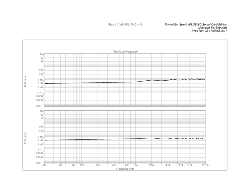
IN this series, THD+N versus frequency, 20 Hz - 20 kHz. At the equivalent of 100 dB SPL (100 V RMS). THD Is Very very even all the way from 20-20k. at about 0.2% THD. In this series, the THD+N at 110 dB SPL is actually LESS than at 100 equivalent dB SPL, telling us that the measurement mostly consists of noise, not THD. That's all the Carbon measurements I have on hand.

-
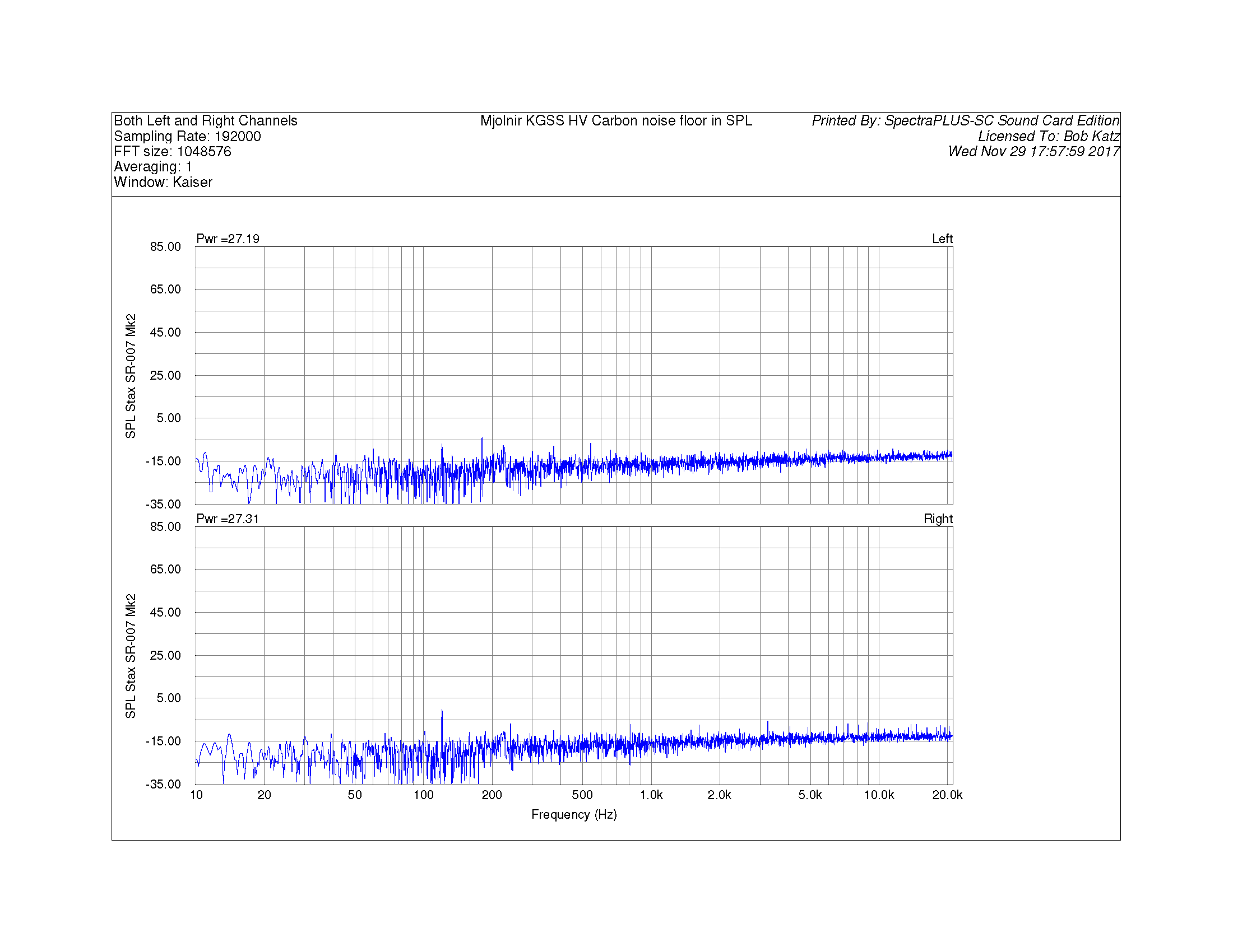
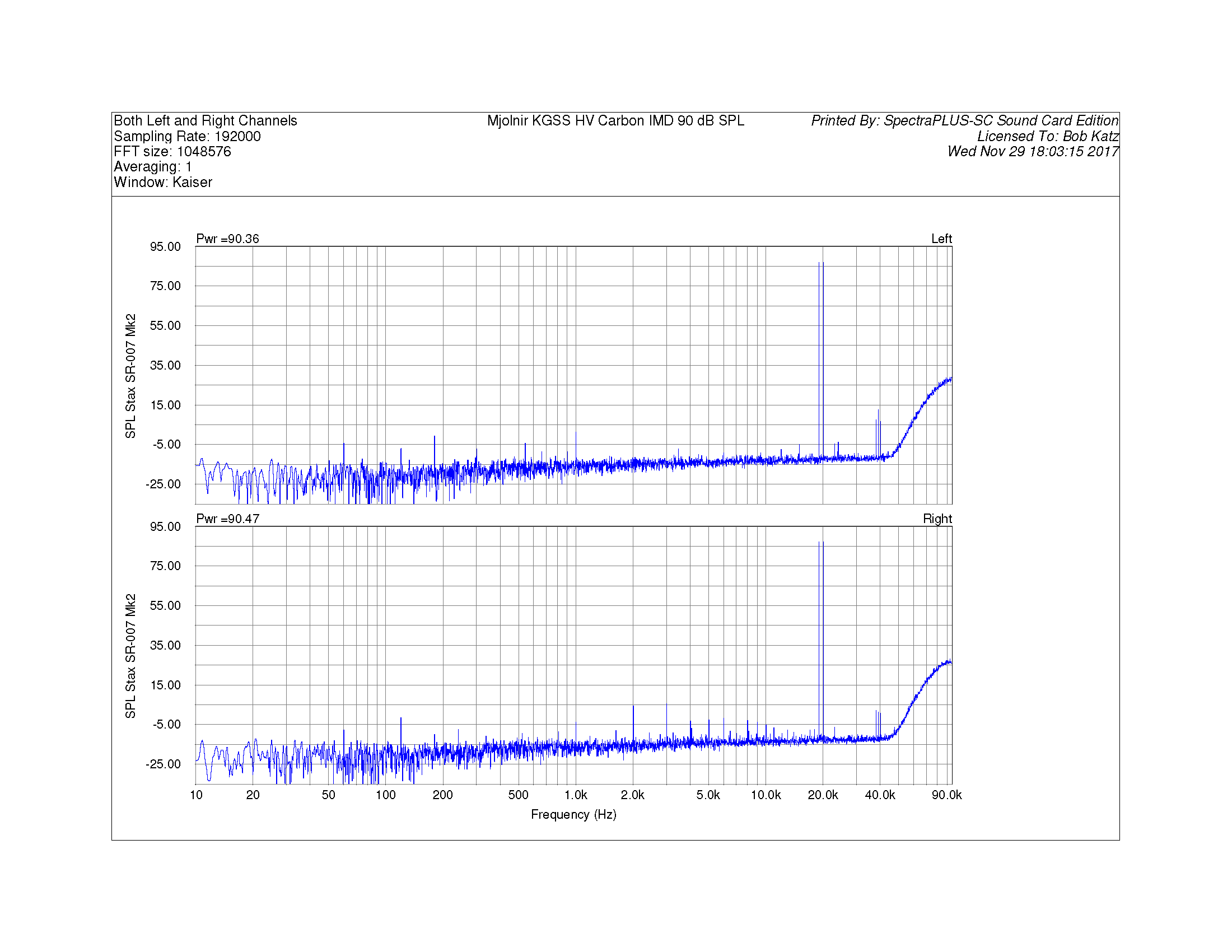
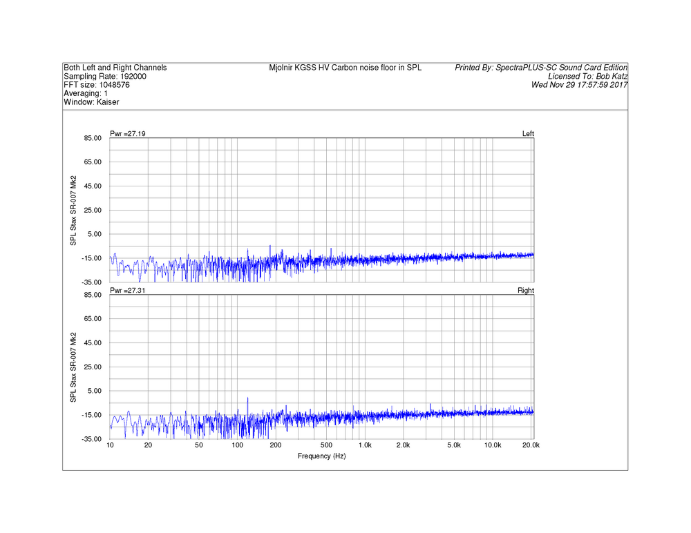
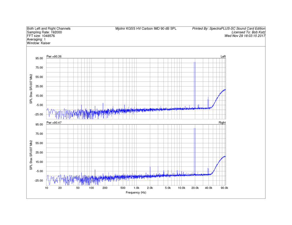
In this series, Mjolnir KGSS HV Carbon noise floor in equivalent SPL is around or below -15 dB SPL. That's MINUS 15 dB SPL, folks. Aha! In this series, I took the IMD with an SPL scale. So at the equivalent of 90 dB SPL for the Stax 007 Mk 2, here's the IMD. It's much lower than the previous IMD measurement, which must have been taken near clipping. Of course there is no meaning to equivalent SPL for a 19-20 kHz signal! But the scale is calibrated for SPL at 1 kHz so you get the idea of the amplitude of the test signal. Here, not so overloaded you can see VERY little 1 kHz difference product at the equivalent SPL of about -2 dB SPL! And no trace of 18 kHz or 21 kHz IMD. So at these already extreme levels, at extreme high frequency levels that would not be found in normal music, the Carbon HV performs exemplararily (if that's a word).
-
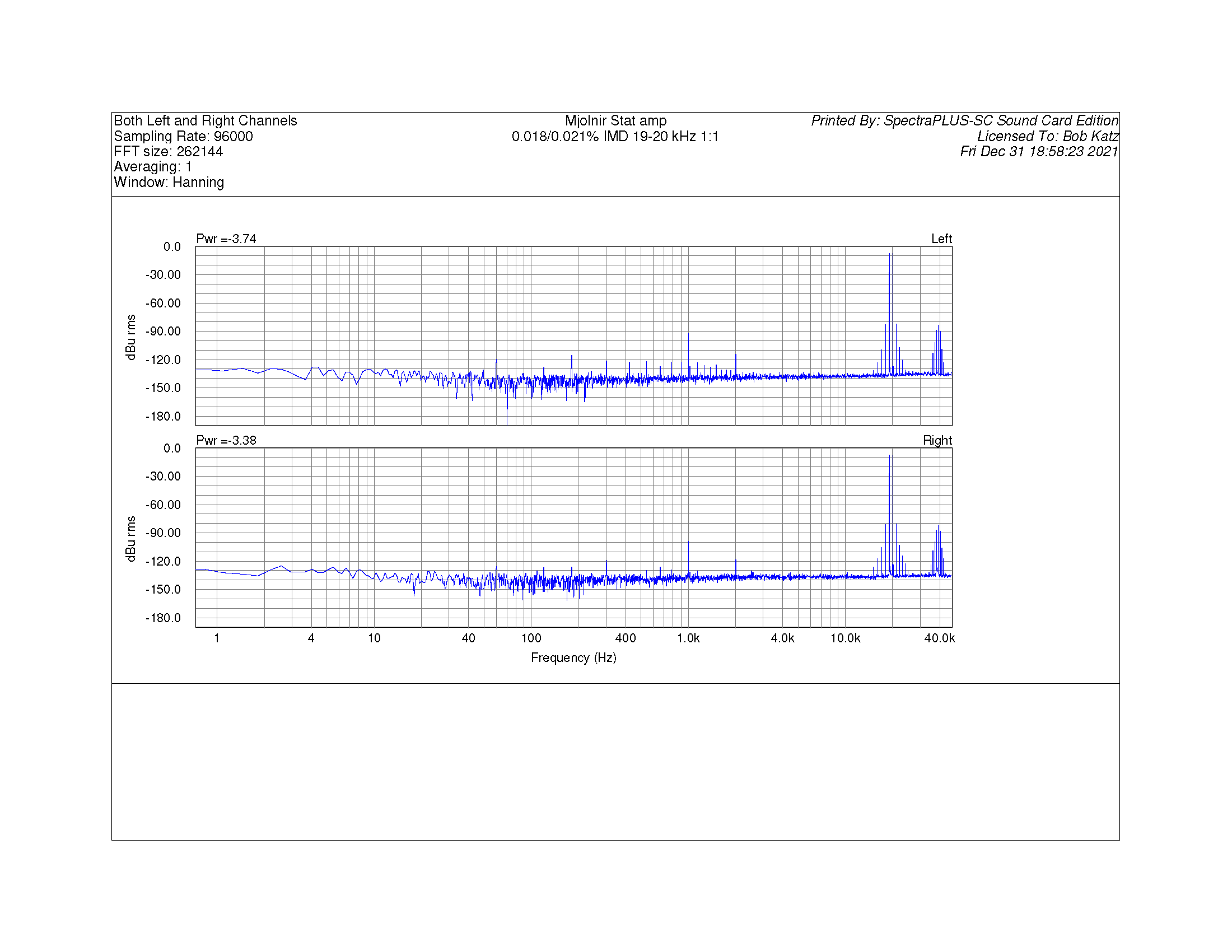
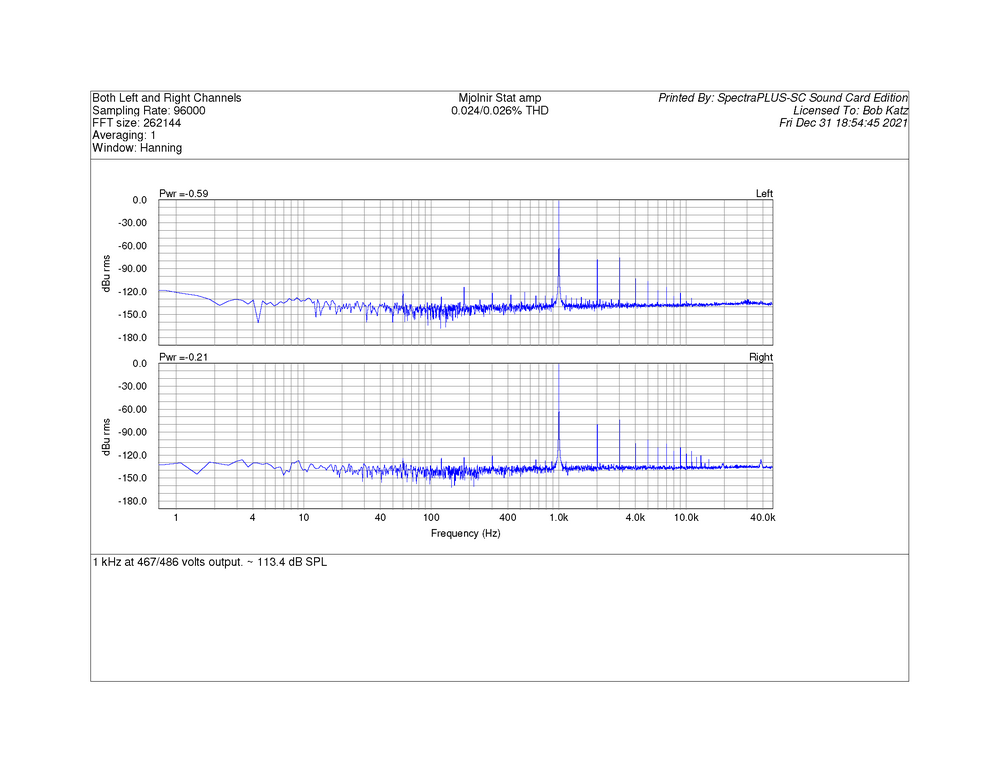
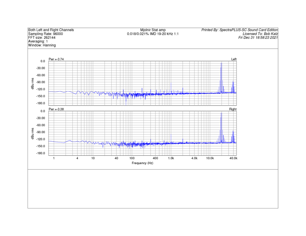
In this series, the right channel freq response is nearly identical so not worth displaying here. Just below clipping, equivalent SPL of 113.4 dB SPL at 1 kHz, produces 0.025% THD. I have an attenuator and by accident, apologize for the inconsistency, the scale is dBu, but my notes say 113.4 dB SPL equivalent. That is a remarkable 467 V RMS. THD is 0.024/0.026% THD at that point. In this series, Mjolnir 19-20 khz IMD. The amplitude of the 18 and 21 kHz products is not exceptional, but to my ears this is still one of the the nicest, most natural and warmest Stat amp I have ever heard. IMD measures 0.018/0.021%. Amplitude is not specified, but I suspect given my scales, it's near 100 V for either one of the partials.
-
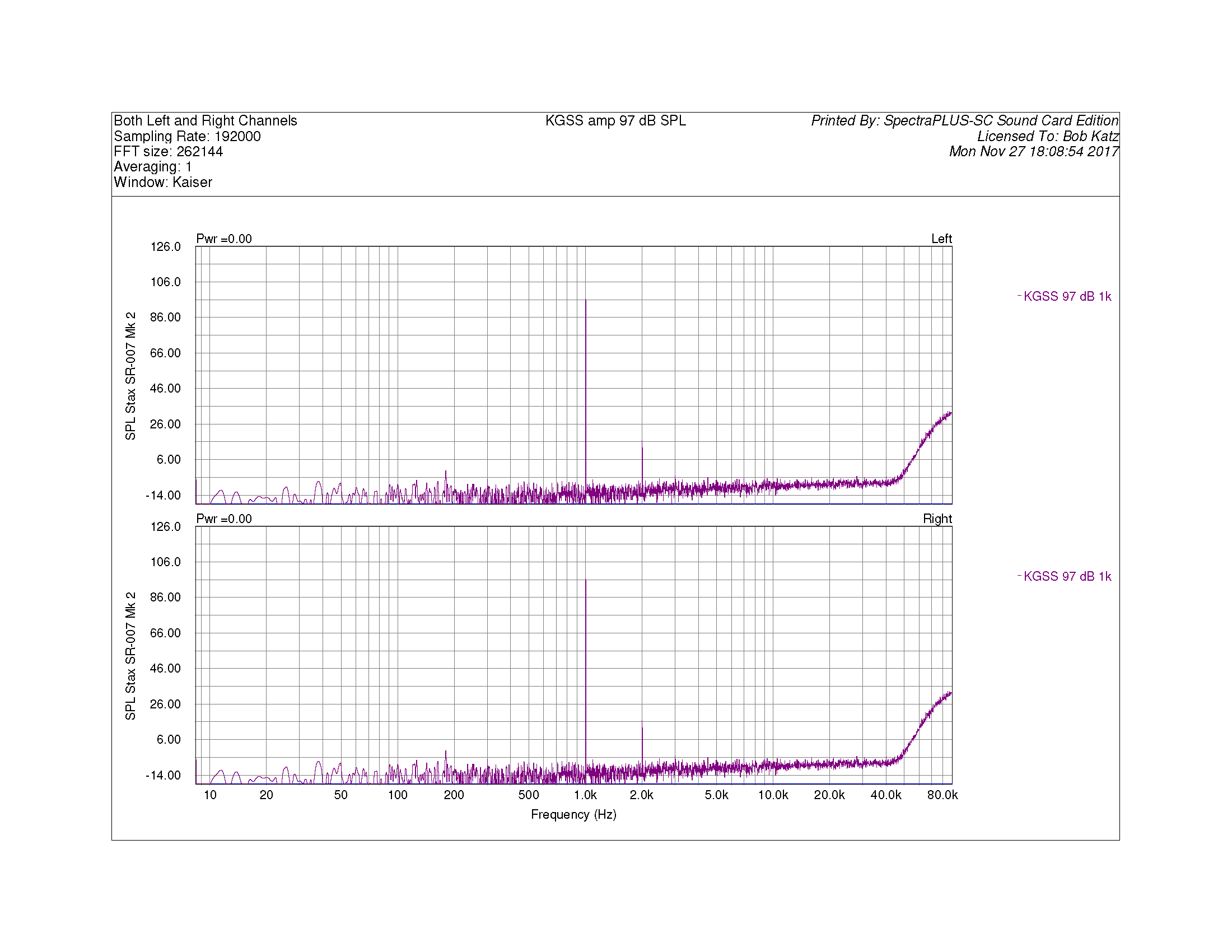
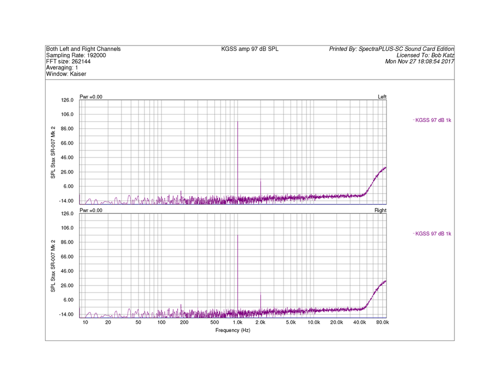
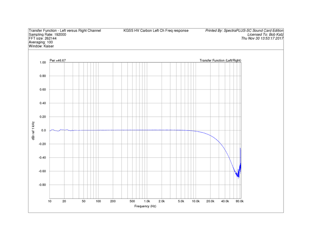
In this series. I like to mark levels in equivalent SPL. Based on the 100 volt RMS rating of the CRBN headphones. So this is close to 100 Volts RMS. Mjolnir spectrum at 97 dB equivalent SPL at 1 kHz. As you can see, it's pure second harmonic with no other trace of harmonic distortion. Second harmonic is at the equivalent of about 10 dB SPL! In this series, KGSS Carbon HV left channel frequency response. I'm using a transfer function with white noise, so for whatever reason at above 60 kHz, the transfer function goes funky and is unreliable. The amp is flat from 10 Hz and only -0.6 dB at 60 kHz!
-
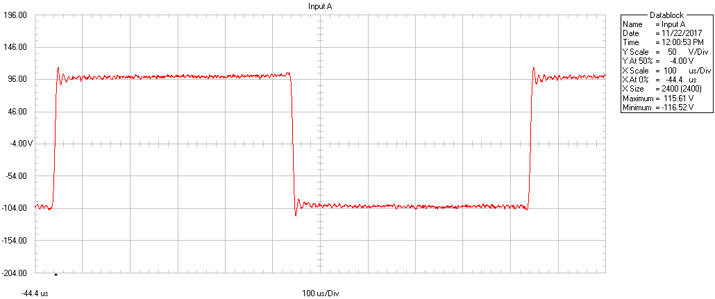
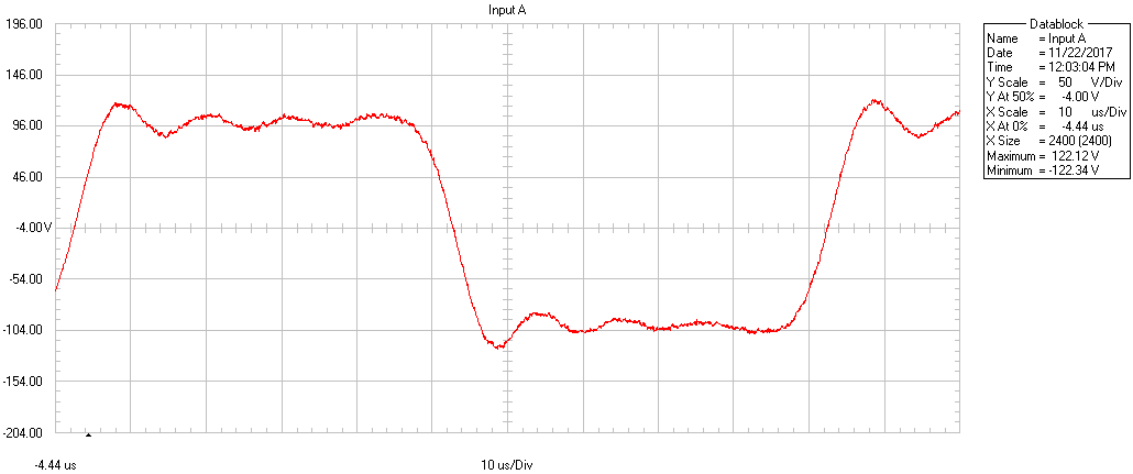
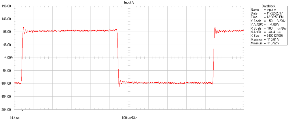
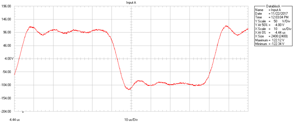
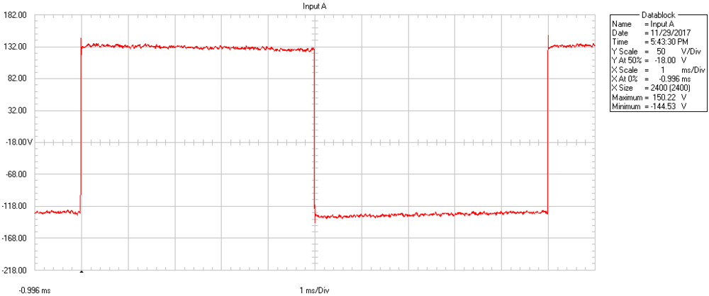
Someone asked me for my equivalent measurements of the Mjolnir KGSS Carbon HV. OK, I have a bunch of measurments. To keep them separate as it seems that image files don't automatically get labels in this forum, I'm going to post them one at at a time. Forgive me if I'm mistaken, the easiest thing for me to do is make one post at a time. Where you see the rising high frequency response at the high end, that's the noise shaping of my Prism ADC/DAC which I use for analysis in conjunction with Spectraplus. Note that at the time I made these measurements I was not aware that it would be advantageous to add a 100 pf capacitor on the load. So these are open loads, and perhaps some of the tiny ringing you see would go away. The first is a digital scope photo of a 1 kHz Square wave at 200 volts p-p from my Fluke Scope. Attached here. In this series Mjolnir KGSS Carbon 100 Hz Square wave 250 V p-p
-
I think I did put up a Carbon measurement in this thread. If it's not here I'll have to dig up the measurements and show you all.
-
Thanks very much! Well, for sure I won't do that!
-
Here's a question on the Bias voltage. I "accidentally" got a Bertan negative-going high voltage supply from Ebay. That means that it has a GROUND which is positive with respect to the 580 volt bias. @kevin gilmoresaid to make sure it's the "positive" model, so, my mistake. HOWEVER, it seems to me that the only difference between negative 580 volts and positive 580 volts is that the absolute polarity of the acoustic outpuf of the headphone will be inverted. Ironically, I proved that Stax AND Audeze CRBN produce inverted acoustic polarity than the + and - markings on the Stax 5 pin plug! I also have not been able to hear any difference between normal or inverted polarity. Consider that the device is 100% bilaterally symmetrical*. And that's my point. For what reason would Kevin have insisted on getting a +580 volt bias voltage? Personally I can't think of anything that a negative bias would produce other than to invert the acoustic signal from the headphones. And that's easily corrected by inverting the audio wires from the transformer secondary or the active amplifier. Besides, as I mentioned, Stax and Audeze CRBNs have been acoustically inverting from the get go, and no one, no where, no how, has ever noticed that! * which explains why, conceivably, moving coil and planar magnetic devices might sound different when inverting absolute polarity, as they are not, typically, bilaterally symmetrical in design.
-
Why so many transistors? anyway, It’s real ironic. Seeking a good, economical way to help “stat-o-philes” to get into our hobby and with an amp that has more drive capability than a typical Stax amp. I already own an expensive KGSS, and it sounds fantastic. Thank you Kevin and Spritzer I thought it would be “simpler” to build a lower voltage amp driving a great transformer than to build a direct drive high voltage amp. But the step up transformer way has its own challenges more than the obvious problems of the non-linearity of the transformer. The problem is an extremely low impedance primary that’s very difficult to drive. I know, I just measured impedance and phase shift of a great toroid. Holy shit that’s tough to drive! There’s no such thing as a free lunch 😞 We shall see if I can come up with anything. And still keep the power supply to +- 24 volts. That’s my intentional design constraint best wishes to all Bob
-
@spritzer I fully agree that if it sounds bad it is bad, regardless of how it measures. And, for example, plain THD is very deceiving at best. I have an expert friend who knows how to interpret differences in the thousandths of a percent. But that’s beside my point. Given the sensitivity of modern test gear that is able to measure noise floors below our perception, there ought to be a test signal that exercises the demon that we audibly perceive. And we should not cease to seek those test signals, because they can lend objective support to our subjectivity.
-
There has to be some measurement that reveals why this sounds so bad. I have Jim Johnston’s Buzz signal as a multitone wav file. You look at the spectrum between 200 and 500 and if there’s distortion product there you know it’s a bad thing. If you can play a wav file in your spectrum analyzer I’ll be happy to send you the wav for testing this module.
-
Thanks for that advice. Crossing fingers
-
I'm not prepared to take an educated guess. But I am prepared to tell you that a very smart consultant I know very well suggested getting negative feedback from the secondary of the transformer to linearize its performance. And that's the implementation I am going to try. I have two transformers, one is an excellent toroid that I found and the other is an unexpected transformer that is very available. If it works, then it will revolutionize this portion of the Stat market. We shall see 🙂
-
Thanks. Dear @simmconnResponding to your Last response first: I honestly thought this was the best single place to have this discussion, to continue a discussion started by @JimL. If I'm going to be way off base not using vector quantities, then I'm definitely not qualified to proceed because vector algegra is not in my skill set. Anyway, thanks, I forgot that reflected impedance is RL x (Np/Ns) squared, oops, sorry. Also, the difference between "apparent power" and "real power" is over my head, so if I mess up below, just tell me I'm full of it and I'll shut up. I'd like to stick to simple scaler algebra as a first approximation if it's not too annoying. Anyway, I'm trying to use JimL's calculations of output stage current to judge the actual load, as opposed to the simple answer of the impedance of a pure capacitor. So, if the secondary has a nominal 3 ma., with a nominal power of 1 watt (per Gilmore) at 106 dB SPL, then 109 dB would be 2 watts, etc. I'll pick 8 watts at 115 dB max level as a worst case. Next, if it was 3 ma at 1 watt, then isn't it it 8.5 ma at 8 watts? Because of i squared R. OK, now can we calculate the rough, approximate reflected impedance load on the source amplifier knowing these quantities: secondary current, power and turns ratio of 33:1? I just want to have a rough idea of what kind of load the power amplifier is expected to drive. When I get to building this box I will measure the actual quantities and actual impedance loads. I guess we'd call it Practical versus theoretical physics. Just like in the Oppenheimer movie 🙂
-
Here's a crazy thought. If the reflected impedance on the primary side actually is 12 k ohms, and the peak power is even as low as 1 watt, then the peak voltage on the primary would be 109 volts. That's crazy. So hopefully I'm way off base on my reflected impedance calculation.
-
@kevin gilmore @JimL Dear JimL, please forgive me for reviving your excellent 8 year old thread! I was definitely not a physics major in a previous life, but I slowly can handle your math. To review, common wisdom thinks that 100 pF is a very high impedance bridging load. But what is the theoretical load based on the current? Can I solve for Z load based on current? I'm trying to use your information to calculate the effective reflected impedance load on the primary (low impedance) side of the transformer in order to know what kind of low voltage amplifier I'm going to need. I'm also trying to expand this to a higher output voltage requirement of 700 volts sine wave RMS = 1980 v p-p at max. Which would be nominally 116 dB SPL peak max with a Stax. Let's round that up to 707 volts sine wave to make the math look easier, which brings us to a round 2000 volts p-p at max with sine wave. My thinking is Z = V / i Next, if i for 1600 v p-p is 3 ma., then i for 2000 v p-p would be 4.6 ma. p-p. Let's round that up to a whopping 5 ma. and see what effective Z load we get: Z = E/i Z = 2000 / 0.005 = 400 k ohms! So that's the nominal load impedance, it seems. Reflected load, if it was nice linear algebra, would be, I suppose Z load x the turns ratio. Turns ratio is 33:1 in my transformer. So, I calculate 400 * 10 eex 3 * 30.3 * 10 eex -3 = 12 kohms! Source voltage = 2000/33 = 60 volts p-p. My push-pull opamps run on +-24 volts, so they can certainly deliver 60 v p-p into 12 k ohms. How does my calculation look to you math experts?
-
And what nominal impedance does the primary of the transformer present to the opamps or the power amp? Since the opamps can drive 600 ohms or maybe less, is it safe to assume the load will be higher than 600? In push pull does each opamp see twice the nominal load on the transformer?
-
BOY DID I MESS UP! Good thing I discovered before I started building: I didn’t consider the output voltage swing of the power amp based on its supply voltage The JLH amp Can take up to 33 vdc supply at 3 amp. Optimistically lets Say 2 volts loss in the output swing OK, output swing 31 volt p-p 15.5 v peak 10.95 v rms sine wave 33x transformer ——-> 361 volts out. Shit. Maybe back to plan A: two opamps in push pull. I have to see if they can deliver up to, say 2 watts conservatively based on Dr Gilmore’s 1 watt 106 dB Stax estimate
-
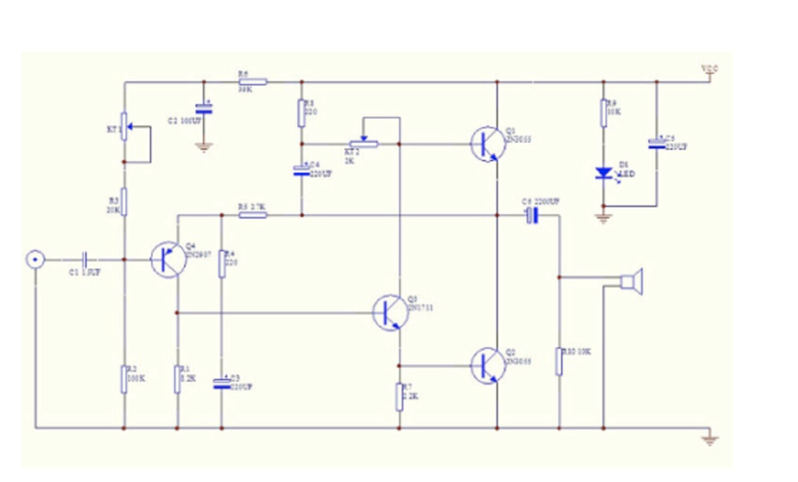
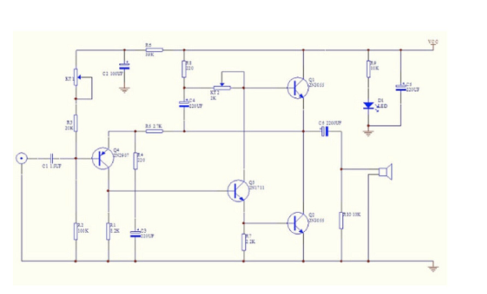
Apparently this is some kind of legendary circuit, based on John Linsley Hood's design going back to 1969, as described in a Wireless World article: https://keith-snook.info/wireless-world-articles/Wireless-World-1969/Simple Class A Amplifier.pdf Well, at least I picked an amp with a good pedigree. I'm sure there are bipolar symmetrical designs of this amp floating around. To my mind the weak links could be the electrolytic coupling caps in this single ended supply design. We shall see.
-
I know very little about power amplifier design. I only know how to bias and other things by instructions of the designer. I picked this one based on instinct and that it can be adjusted to Class A. Is it such an old fashioned design that it's not going to sound good? Schematic is attached. I might change some of the caps to film in due time.
-
I put a Muses board by Academy Audio into an AMB M-cubed headphone amp I built. Wrote that up at Innerfidelity when it was still in existence. I set up a switch between a passive TKD 1 dB/step attenuator and the Muses attenuator. After hours and hours and hours of listening, I'm still not sure if I can tell the difference, the Muses chip is that good. These both go into the input opamp through a double pole front panel switch. The Input opamp is either an OPA 604 or 627, I forget what I put in there.
-
I wish I had just titled my main thread "Building an Energizer from Scratch" as I have more questions than just about the zeners. Thanks for your understanding! So, now I've decided to use a linear Class A amplifier board to drive the transformers. I think that's a better idea than push pull opamps or Class D noisy stuff. So, a question about heat sinking: Taking a chance, I ordered two of these "JLH 1969 Cass A Amplifier" boards from Ebay. Just search for the description on Ebay "JLH 1969 class A amplifier stereo high quality PCB components assembled !" as there are tons of Chinese sellers. Hopefully I picked a good seller. Anyway, We'll soon see how they perform. I can measure and I have load resistors. About the heat sink required for these boards. For Stat headphone purposes, do you think just screwing the aluminum plate of this amplifier to the sides of the Topping amplifier chassis will provide sufficient heat sinking?
-
This topic has stretched from just zeners to another OT transformer energizer build thread :-). I apologize if I'm going over old ground and if any of you head-case old timers can point me to threads discussing building a passive energizer I'd appreciate it. Next question: Transformer rated watts. Isn't a 15 watt transformer under rated in terms of its insulation voltage breakdown? My calculations are that with a 5000 ohm to 4 ohm ratio, that's nominally 35:1 voltage ratio. 15 watts at 4 ohms comes to 7.7 volts RMS with sine wave. But 35 x 7.7 volts ----> only 269 volts on the high impedance secondary. If we desire, up to, say, 600 volts RMS on the secondary, aren't we overdriving the transformer by at least 2X its original voltage rating? I'm not worried about watts because the headphone load is very high impedance. But again, what about the My next question comes again back to my choice of amplifier. What is the reflected impedance back to the 4 ohm tap? In theory it's VERY VERY high because the headphone load is extremely high impedance. Even though the DC resistance of the 4 ohm tap is maybe 0.1 or 0.2 ohms. At least I need to be capacitively coupled. These opamps I'm considering can drive down to 75 ohm loads. Am I going to run out of drive capability with a discrete opamp driver?
-
Another test picture shown is a polarity test signal. The amp is non-inverting, based on pin 2 going positive to +-marked pin on the Stax connector. I guess that's something. Although, as you would find from my measurements of Stax and CRBN headphones using a cheapo Mini-DSP Ears, cross checked wih a calibrated measurement microphone --- these headphones invert absolute polarity! But you know what, and here's my theory: Those who say they can hear a difference when absolute polarity is reversed made their judgments listening to moving coil loudspeakers --- not electrostatic headphones. A moving coil has an inherent linearity difference between out-going and in-coming due to differences in the spring/cushion of the coil and spider returning to the zero point. And also consider that magnets themselves are very non-linear in their pull at different distances. Not so with capacitive. And an electrostatic diaphragm in push-pull from the stators is bilaterally-symmetrical, so there should be no distortion or strength of difference between push and pull. Personally I have never heard an audible difference between inverting and non-inverting signals with E-stats. The Audeze CRBNs have their nano-material embedded equally throughout the diaphragm, while Stats with metallized diaphragms are coated on just one side (I think, am I correct?) so at least theoretically there could be a difference between push and pull but we are talking about microns of distance difference here.