


decoherent
Members
-
Joined
-
Last visited
Everything posted by decoherent
-
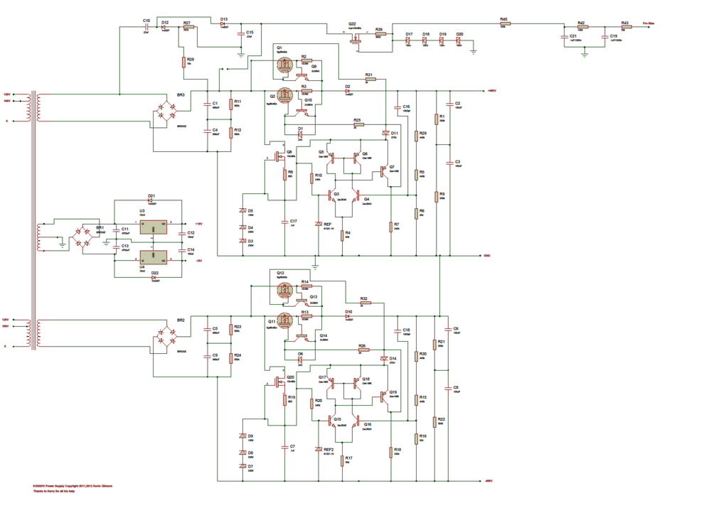
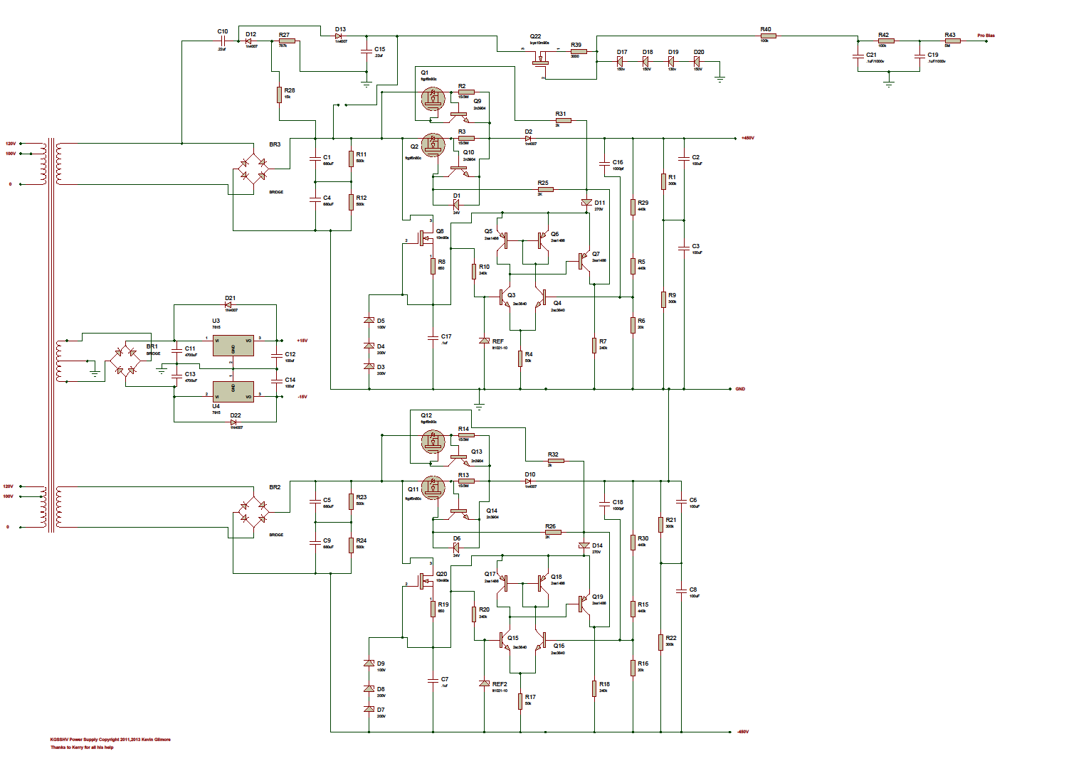
Thanks to all. I think this is the psu?
-
An we are three! I do nto have the boards yet and would be grateful if Birgir coudl sell a set to me as well. I have been hapy with my three stages 300B SE + transformer (built by myself) for long time but the KGST seems to be still the golden reference for staxes. Kind of gave up the idea to build one as the last group buy has been lon gago. Kevin loaded all the diagrams in a share when he retired, but not sure if that are still up to date. Biggest concern of mine woud be components availability. Is there a recent verison of KGST with currently on the market components? Antonio
-
Sent from my GT-I9300 using Tapatalk
-
Well, a three stages SET 300B with 1:2 OPTs is the amp I use with my MK1 and is simply amazing. Sent from my GT-I9300 using Tapatalk 2
-
Kevin, what happened of the original design to resort to the usual EL34? I personally prefer real triodes to pentodes, even when triode strapped, and parallel 5687 as power stage did sound an interesting idea (also one of my fav triodes). What's the reason? Filament supply? Not enough gain? Simply more parts? Thanks.
-
Kevin, what are the advantages of the srx input stage? How do you calculate gain and input/output impedance? Will two ccs in place of R1 and R6 make possible to avoid the global feedback?
-
I've to say the out stage does looks to me a lot like a "paralled" srrp...... or you are referring to the tail side only being ccsed? Sorry for the obviously dummy questions. Thanks.Thanks Kevin. The first stage is interesting indeed. I've never seen such a ccs (that doesn't want to make a statement of any sort of course). How the CCS works? Is its connection crossed between phases to balance the two outputs? Thanks.... now my ears are sticking out:-) Electronics Schematics are still my favorite. Will yo be willing to publish those? are we talking about close to 1kv ptp output with 2 V input signal? Thanks.Mmh... not sure I understand how the whole thing works then. We need 580V between the diaphragm and each stator. To do this we need to connect the diapraghm to the +580V and the stator to the 0V. As we have two stators they will be both connected together to the bias 0V shortcutting the signal output. I'm using a tube PP amp plugging the stator to the OPT primary connections. I'm going to duoble the 300ACV from the B+ tranformer and use it as bias. This is why I thought it was necessary to have the two 10mohm resistors to separate the two stators, still providing a ground rference for the bias, and was puzzled only about the extra 5Mohm resistor between Bias V+ and diaphragm you seem to suggest for security reason. To give an example please have a look at the secodn schematic in the auridux page: http://dddac.de/tp08.htm The only difference in my case is that I can't take the bias from the B+ as it is too low and need to source it via a doubler. Thanks.Spritzer or anybody else havng already done this, when implementing the BIAS for the stax daphragm, you need to set one resistor connected between each stator and bias 0V to have the ias voltage betwen the diaphragm and the stator (e.g. 10Mohm). Do you still need an extra resistor (5Mohm has been suggested) in series with the bias voltage and the diaphragm in this case? Apologies if I'm getting this completely wrong but, how they say, if you don't ask you will be stupid for ever. Thanks.Rodrigo, can you please write me in for 4 5-pins and 4 6-pins boards (with pins)? Please send me a PM as I can't do it. Also, is there any board left? Thanks, A
Important Information
By using this site, you agree to our Terms of Use.