


GeorgeP
-
Posts
517 -
Joined
-
Last visited
Content Type
Profiles
Forums
Events
Posts posted by GeorgeP
-
-
Thanks Wachara.
-
Wanted to add an HE90 jack but wanted to make sure I have the wiring correct from the front view. Not something anyone wants to take any chances on, but surprisingly little info out there on this (other than an old head-fi thread from 2010):

Was planning on using the +500 supply for the bias and add another 5M resistor in series.
-
Great work, Jean-Denis!
And just confirming for others that you flush mounted your takman resistors without any noise issues. Could help future builders.
-
Did you find that you needed the servo?
-
It's not just a silk line?
-
3 hours ago, G600 said:
I have just checked KG's gerber files, and they don't have the trace.
Waiting for the master's input before modifing anything. "Better safe than sorry"

Here is a pic of a board I have:

-
Yes, your board is missing a trace in that spot. You have the slightly shrunk version. Looks like the trace got dropped somehow.
-
No board bugs in your version - pretty sure Inu's boards were from the initial run before the corrections were made. But your board is 4oz copper which means everything needs to be extra-perfect.
-
Pretty much anything around 30v and down is fine. Don't worry about the batteries being exactly 740v - in fact I am only aware of them not being absolutely perfect.
But worrying about fine adjustments without plugging in a set of earspeakers at this point is premature (unless you are lucky and your t2 is silent without having to do some adjustments to the pots).
-
There are actually quite a few such references in the T2 thread, won't look for them all, but the following was found fairly quickly:
-
5 minutes ago, sorenb said:
Can you elaborate a bit on the reason why you believe that the circuit design is flawed? does it include both PSU and AMP board from the Carbon Group Buy?
He's not referring to the carbon.
-
So we have gone from it being an excellent circuit that could not be improved upon to now a flawed circuit design? Clearly above my pay grid, but seems to be a lot of revisionism occurring of late.
-
 2
2
-
-
With higher parts count and everything sharing the same ground plane, it would be questionable as to whether there would be any benefit - if I recall that was the reason Kevin stated in leaving it out. But as always the proof is in the pudding. For example the t2 has a massive ground plane, but many folks have experienced noise issues nonetheless.
-
1
-
-
1 hour ago, sorenb said:
Meaning that the GND from the PSU are connected two times at each AMP, and uses the signal GND for ref for the HE90 voltage divider?
I think he is referring to the fact that Kevin purposely left out the ground plane - though he said there would be no difference. Maybe Kerry can do some noise measurements when he finishes his.
-
26 minutes ago, spritzer said:
I would never use more than 330uf in this circuit which is what it was designed to use. Two 680uf in parallel gives 340uf.
Just going by memory, but I thought Kevin suggested the 680uf 550v caps when he was designing the circuit and doing the board layout for the group buy.
-
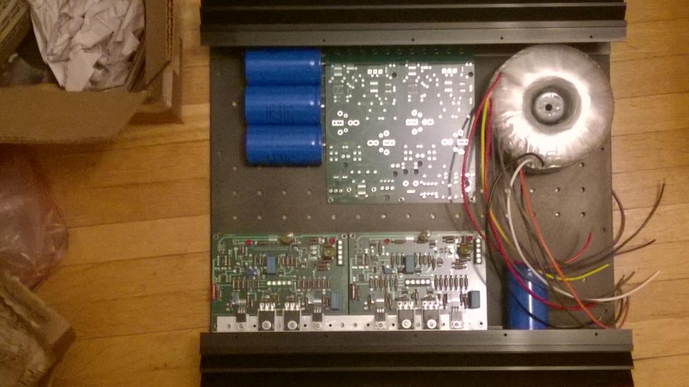
1 hour ago, spritzer said:
A lot of this amp is an example of how not to wire any electrostatic amp. There is so much fail in there but lets start off on the big stuff, how the caps are mounted... Never do something like that!!! Uninsulated spades on all of the AC input wiring when they clearly should be insulated. Input wiring runs right under the transformer when it should be kept as far away from it as is possible. Last but not least, the output wiring. Twisting it like that is bad idea as it adds to the output capacitance of the amp.
what would be the concern with the caps? Isn't it kind of like point to point wiring?
-
46 minutes ago, purk said:
That way I can entertain Mulveling at any time. However, he does listen at louder level than me.
since this is a DIY thread, care to post some internal pics. Interested in seeing how the caps are mounted given the size of the chassis.
-
That is great news!
-
suppose opening the sheet could have helped, but google docs and my phone don't get along.
-
What would the potential price on the TO-71 be? And would it be A or B?
-
2 hours ago, G600 said:
Sure, we always need something better.
That said, nothing blew up, adjusting the batteries was very easy, and I didn't knew I would go that far without electric trouble.
Seven months sourcing and testing parts... only a few steps away from music !
C'mon, pick it up J-D! Why no music yet?
-
Looking good!

-
On 11/12/2015 2:13:52, sorenb said:
if your chassie is 2U or even less you actually need the Golden Reference Single , or Single NoCaps board
Was thinking something like this:
-
1
-
-
Was talking about taking a bath on a 25k source (selling for 8-9k now) and picking up a 30k source plus the Yggy. Add up all the dosh spent and to be spent and well...
-
2
-


Soldering station recommendation
in Do It Yourself
Posted
I use the Aoyue 968A+ SMD Digital Hot Air Rework Station.
It has worked flawlessly for 3 years of hobbyist DIY, and has the hot air gun for smd (but I use it for heatshrink, which is convenient). Has a smoke sucker too, which works well, but you have to clean the filter out every once in a while. Probably not the same long-term quality as OKI/Metcal or Hakko if you are cranking out an amp or two every day of the year, but more than good enough for our purposes.
Amazon has it for $175, shipped - http://www.amazon.com/Aoyue-968A-Digital-Rework-Station/dp/B006FA481G