demonkuro
-
Posts
29 -
Joined
-
Last visited
Content Type
Profiles
Forums
Events
Everything posted by demonkuro
-
goldenreference high voltage power supply (GRHV)
demonkuro replied to Pars's topic in Do It Yourself
Thanks a lot. -
goldenreference high voltage power supply (GRHV)
demonkuro replied to Pars's topic in Do It Yourself
kgsshvpssicfetsinglenewleftfatsws - cadcam.zip It is a fat one. The thin one with CPC1117N has only the kgsshvpssicfetsinglenewrightsws3.ZIP.It is only right, no left.
-
goldenreference high voltage power supply (GRHV)
demonkuro replied to Pars's topic in Do It Yourself
kgsshvpssicfetsinglenewleftSWS.zip doesn't seem to exist in Google Drive, who has this gerber? Version 1.8, thin version and the one that contains the CPC1117N, many thanks. -
goldenreference low voltage power supply
demonkuro replied to kevin gilmore's topic in Do It Yourself
Yes, I got it wrong, thank you, I should use the middle one 1.5K to adjust the voltage, not the one close to DN2540, the 0.48 version PCB I use. -
1. I use a portable multimeter. 2. (1) Only put neg lead, it has a screeching sound. (2) Put the neg lead first, which has a screeching sound, and then put the pos lead on the other end of the R42 and the screeching sound disappears. (3) Put the pos lead first, there is no screeching sound, and then put the neg lead on the other end of the R42, and there will be no screeching sound. 3.Only when measuring R42 in the R channel, near the E88CC (6922) tube, a screeching sound is generated. When the machine is cold, everything is normal when it is turned on, and all output DC offset is only about -7V. After a while, when the machine gets hot, the DC offset output of the R channel will become larger and more than -100V. The voltage of the two batteries of the R channel will decrease and become different, the voltage of the two R42 will also decrease, and the voltage of the two R42 will become different. One R42 becomes 6.2V, and the one close to E88CC becomes 5.8V, they are irregular and do not drop to this value every time. Even when the machine is cold, as long as you measure the R42 close to the E88CC, the voltage of the battery will immediately decrease, the other R42 will also reduce the voltage, and the DC offset of the output will become -100V. 4.I used the original T2 PCB, but based on JoaMat's T2 modified I replaced some parts. I replaced 2sa1486 (Q16, Q17, Q18, Q19) with stn9360. Replaced all 2SC3381 with 2 MPSW06. Replace 2sa1486 (Q1, Q2, Q3) with KASA1156. Q6, Q7, Q11, Q12 have not changed, they are still 2sa1486. Are these changes in mine that make it oscillate? I only have one multimeter and I can't measure multiple locations. Thank you,simmconn. Thank you, Kerry, for reminding me. My Q23 HFE is 48~50, should I choose a lower HFE? Like 30? I'll try it.
-
goldenreference low voltage power supply
demonkuro replied to kevin gilmore's topic in Do It Yourself
My GRLV set R7=1.5K and R8=2.15K, they seem to get a 24.3V output, but it doesn't turn out to be that way, it only has a 16.99V output. All the LEDs are on, the LT1021 output is correct at 10V and the AC input is 28V.Am I missing something? -
When I approach the EL34 with my ear, there will be noise in one of them, and when I plug in the headphones, there will be noise in the headphones When the outputs are measured using the multimeter AC function, their readings are constantly changing, like flashing. When I use a multimeter to measure the voltage of R42, there is a screeching noise as soon as the black measuring pen (negative pole) touches R42, and they seem to be from tubes. The red pen (positive electrode) does not make noise when touched. When the voltage reading of R42 changes, R42+ and R42- will not change in the same proportion, they will become different, one large and small, such as a 5.8v and a 6.4v, then the DC offset will become very large up to -80V or even -110V
-
All output voltages of the PSU are normal and all LEDs are on
-
I don't have an oscilloscope, I don't know if it has oscillations. If it does have oscillations, what should I do about it?
-
I had a strange situation with my T2, when I set the R42 (22K) in all the batteries to 6.55V through the RV2 (10K), everything was fine, DC offset to ground was around -10V. When I measure the negative voltage of the battery, DC offset to ground suddenly becomes -150, I go to check R42, and I find that the R42 in the existing battery becomes 5.8V, some become 6V, and some become other values. I didn't adjust anything, and after constantly measuring the R42 of different batteries, they changed back to 6.55V, and DC offset to ground also returned to around -10V. Sometimes when I plug in the headphones for a while, DC offset to ground also gets bigger, and when I go to check the R42, I find that they also change, and after measuring different R42s, sometimes they change back to 6.55V, sometimes they don't. Sometimes DC offset to ground gets bigger when the power is turned back on, what's going on?
-
Yesterday I did a continuous 5-hour test. I found that the voltage of the battery will decrease, the voltage from -549/+206 at 30 minutes, and then to -549/+202 after 5 hours, only the positive voltage will decrease, and as the positive voltage decreases, the output voltage to GND will also change from about -5V to -20V。 why is only the positive voltage not stable? At the same time, I found that the output of the R channel to GND must be above -549/+208 to be stable, is it okay to have such a high voltage?
-
Cheers! KGOOS is this one? Can it keep the offset set at 0 all the time? It seems interesting, but it requires a +/-15V supply, so it needs to add power. Maybe I'll try it later.
-
C/D of R channel is about 1.6~2.2V,It's a bit higher than the L channel. Adjustable resistors are a method that can be tried, I will try, but they always drift, C/D always changes over time, and it seems difficult to stabilize at 0 all the time. Maybe I can also buy some resistors close to 6.2K to replace it and test it. Thank you for helping me again and again!
-
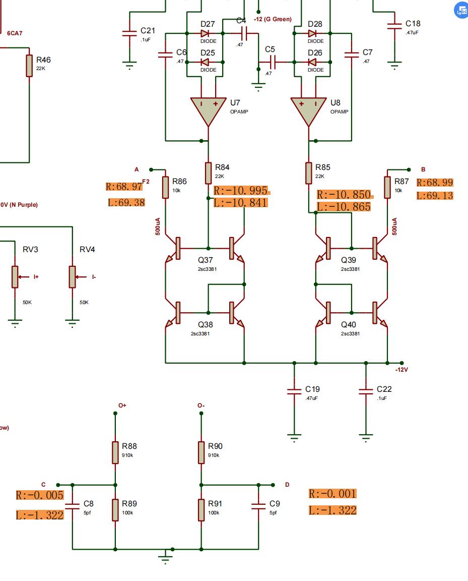
Yes, I use “original” DIY T2. After I replaced Q24/Q25, Q26/Q27, Q28/Q29 on the R channel and temporarily borrowed a 910K resistor from the L channel, the two outputs of the R channel are balanced. The output of the R channel is now about 10 times that of C and D. But I found a difference from the L channel, when the battery voltage is above a considerable range of 750V (-549/+201), the output is 10 times C/D. If it is lower than 750V, such as 745V, then the output voltage will be about 10 times more C/D, such as 15 times. Since the L channel now lacks an R90 (910K), it presents exactly the same situation as the previous R channel. The same output is unbalanced, and there is a 4V voltage difference around Q24/Q25, which is exactly the same as yesterday R channel, so it can be seen that these reasons are only caused by R90, I replaced Q24/Q25, Q26/Q27, Q28/Q29 should be in vain. But no matter what, it's always good to find the cause of the problem. Since the L channel is now unbalanced due to the lack of resistance, their voltage has no reference value. In R channel Q24 have 1.9V, Q25 have 1.3V. Voltage drop of R50 is 1.1489V, R51 is 1.1493V, R54 is -0.4793V, R55 is -0.4840V. Then there seems to be only one problem now, that is the values of C and D are too large to approach 0. Can you tell me why? Thank you again !
-
You are right! R90 is dead. Before I checked on the PCB and it didn't catch my attention, just now I removed them all and found that the R90 is dead. I disassembled Q24/Q25, Q26/Q27, Q28/Q29 and tested them. The HFE of Q28/Q29 was basically the same, at 70.6. It's pretty much the same as on the L channel The parameters of Q26/Q27 are Vt=782/762mv, Cg=99/99pf, RDS=7.6/7.8Ω The parameters of Q26/Q27 are Vt=968/1010mv, Cg=112/116pf, RDS=10.9/10.9Ω These discontinued ICs are rare and expensive, and it is difficult to find two that are highly close. Parametrically, they don't seem to be very different. Perhaps they have inconspicuous injuries, I may need to replace them all. When the replacement parts arrive, I will try further.
-
Thank you very much for your patient guidance. The voltage drop on R18 R19 R20 are basically the same in every channel at about 2.84~2.87V. R17/R27 is about 2.94~2.95V in every channel, R14 is R+:124.4V, L+:128.6V, R24 is R-:134.4V, L-:128.6V. I measured the voltages of C and D, and I found that they were almost 10% of the output, except for R-, where R(D) was almost 0, but R- was probably -42V or more. IN+/IN- of the opamp on R channel is about 0.002~0.008V, on L channel is about -1.16~-1.33V. At the same time, I found that in L channel, as long as the difference between the two batteries is within 10V, such as 740vs749, then the output can always be stable at 10 times that of C and D. But in R channel is different, only when the difference between the two batteries is within 1.5V, the output of R+ can be stabilized at 10 times C. The output of R- always seems to have no correlation with D, regardless of the battery voltage. Now the problem is that in the L channel, the voltage of C and D is too high, they always drift at 1.2~1.6V, so the output of L always drift at 12~16V. The problem with the R channel is that the output of R- is not associated with D, or the voltage of D is incorrect. Am I analyzing correctly? I checked all the diodes to make sure they were not in the wrong direction. And I was using MLCC, but I replaced it with the new one but the same result.
-
Yes, I did. Q24 (J79 in R+ ) is good,and I changed Q24 to Q25, the result is still the same, this 2SJ79 should not be broken
-
Today I tested again, I replaced the LF353 of R to L, and replaced the 2sc3675 of Q33, Q32, Q31, Q30 and they all replaced the same HFE37 one, and the result is still similar to yesterday, I did an hour of testing and recorded it as follows. After 2 minutes: L+ is -13.7, L- is -13.7, R+ is about 0V, and R- is -55V. After 30 minutes: L+ is -12.9V, L- is -12.9V, R+ is about 0V, R- is -50.3V. After 60 minutes: L+ is -10.8V, L- is -10.8V, R+ is about 0V, R- is -49.2V. R+ always drifts between -0.5V and +0.5V, no matter how long it takes. Then I also recorded both outputs of the LF353. After 2 minutes: LF353(L+) is +6.8V, LF353(L-) is -4.2V, LF353(R-) is -4.07V, LF353(R+) is +7.17V. After 30 minutes: LF353(L+) is +10.1V, LF353(L-) is -0.3V, LF353(R-) is +0.6V, LF353(R+) is +10.7V. After 60 minutes: LF353(L+) is +11.09V, LF353(L-) is +1.58V, LF353(R-) is +1.01V, LF353(R+) is +11.08V. At the same time, I also recorded the voltage of some points, which is a little different from schem. Finally I measured 2sc3381 near LF353 and I found that their HFE is very different, I did not disassemble them, I measured directly on the PCB. The results are as follows. L-:447/5.10, L+:428/5.41,R+:452/5.22,R-:328/5.79 Are these 2sc3381 HFE differences the reason why I can't get zero bias for all outputs?
-
R+ always drifts between -0.5V and +0.5V. All EL34 are bright and hot, and I shuffle their order every time I test, but the result is the same.
-
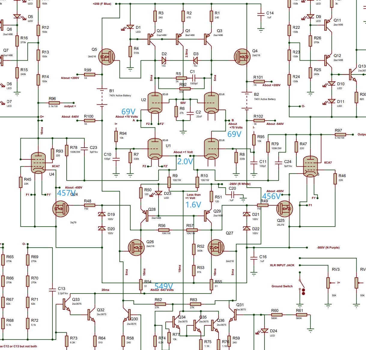
Today I checked all the 2SK216 and 100V diodes and they are all good, and the 15V diodes and 1N914 I checked should also be good. Q33-Q32 is also good, HFE is at 50-52. Then I recorded the voltage output to GND, @battery 740V (+193/-547).PSU:+251.3(+250V)+498.6(+500V)-503(-500V)-266.7(-260V)-564.5V(-560V) Cold crank: L+ is -15V, L- is -15V, R+ is about 0V, and R- is -61V. After 30 minutes: L+ is -13.4V, L- is -13.4V, R+ is about 0V, R- is -56V. After 60 minutes: L+ is -12.3V, L- is -12.3V, R+ is about 0V, R- is -52V. After 90 minutes: L+ is -11.6V, L- is -11.7V, R+ is about 0V, R- is -52V. Then I also recorded both outputs of the LF353. Cold crank: LF353(L), output 1 is 1.65V, output 2 is -6.65V, LF353(R), output 1 is -0.65V, output 2 is 9.66V. After 30 minutes: LF353(L), output 1 is 6.2V, output 2 is -1.63V, LF353(R), output 1 is 0.96V, output 2 is 11.07V. After 60 minutes: LF353(L), output 1 is 6.96V, output 2 is -1.63V, LF353(R), output 1 is 0.05V, output 2 is 11.07V. After 90 minutes: LF353(L), output 1 is 11.09V, output 2 is -2.28V, LF353(R), output 1 is -0.15V, output 2 is 11.07V. During the 90-minute test, the voltage of the 740V battery dropped by about 2V. All the LED lights are on, the AMP radiator is very hot, and the PSU radiator temperature is lower. It seems that only R+ is always working fine?Over time, the voltages from the other outputs to GND are always drifting. This confused me and I didn't know what else I should check.
-
Bias voltage before the 5M resistor is 574V.
-
HI!My exploded T2 is back to life. Today I finally connected the PSU to AMP after replacing all the damaged parts. Following the instructions in the forum, I set the R42 (22K) at 6.55V using RV2 (10K) and then set the battery at 740V (+190V/-547V) using RV1 (2K). When I was ready for success, I found that it was not so simple. The output R- to GND was -91V, R+ to GND was 0.05V, L+/L- to GND was -28.6V, and the BIAS (574V from PSU) was only 384V after 5M resistance. I tweaked RV2 (10K) and RV1 (2K) to get a near-zero DC output, but I couldn't get a 740V battery at the same time and made the DC output zero. Do I need anything else? Or are some parts damaged again? I checked, but nothing seemed to be found.
-
You are right. If I had noticed this in the first place, it wouldn't have exploded. I spent the whole day checking which parts were damaged. Some parts were damaged but could not be seen from the outside, and it took a lot of time to check all the parts one by one.
-
Finally found the cause of the explosion.The cutouts in the radiator are slightly crooked, and despite the fact that I used insulation pads and insulation gaskets, they unbelievably caused a short circuit. Silicone pads have no problem with their insulating properties, but they are too thin and can create physical contact in some extreme cases. I have replaced them with ceramic insulation pads and what are indeed much safer. This is an important lesson for me. However, it is good to find the cause of the problem.
-
The PCB is 15mm from the bottom cover, they are not accessible, thanks for the reminder, that should not be the cause of the explosion