jsts
Returning Member
-
Joined
-
Last visited
-
I am now in my fourth month of using the amp. The hissing went away 2 weeks ago. All by itself. Completely. Either the warming up was completed, or a miracle happened. Don't know. But I'm glad
-
spritzer, thank you for your participation! The hissing comes regardless of whether the headphones are plugged in or not. There was no hissing at one time (e.g. yesterday), and then again today. That is, the issue occurs often, but not always. The hissing is definitely coming from the amplifier. Not from the headphones. Obviously, I need to open the bottom cover of the amplifier and take a look with my own eyes. I'm just trying to gather more information now about what I should pay attention to.
-
Oh, yeah. Right. I recall that in some thread (DIY?) on this forum, the guys encountered something similar. Many thanks! I'll check it out! That said, of course, if Justin shares his thoughts, I would greatly appreciate it.
-
Do you mean corona discharge ? That's interesting... Yes, it just so happens that I was able to purchase an amp with Alps RK50. I like it too 🙂 Thank!
-
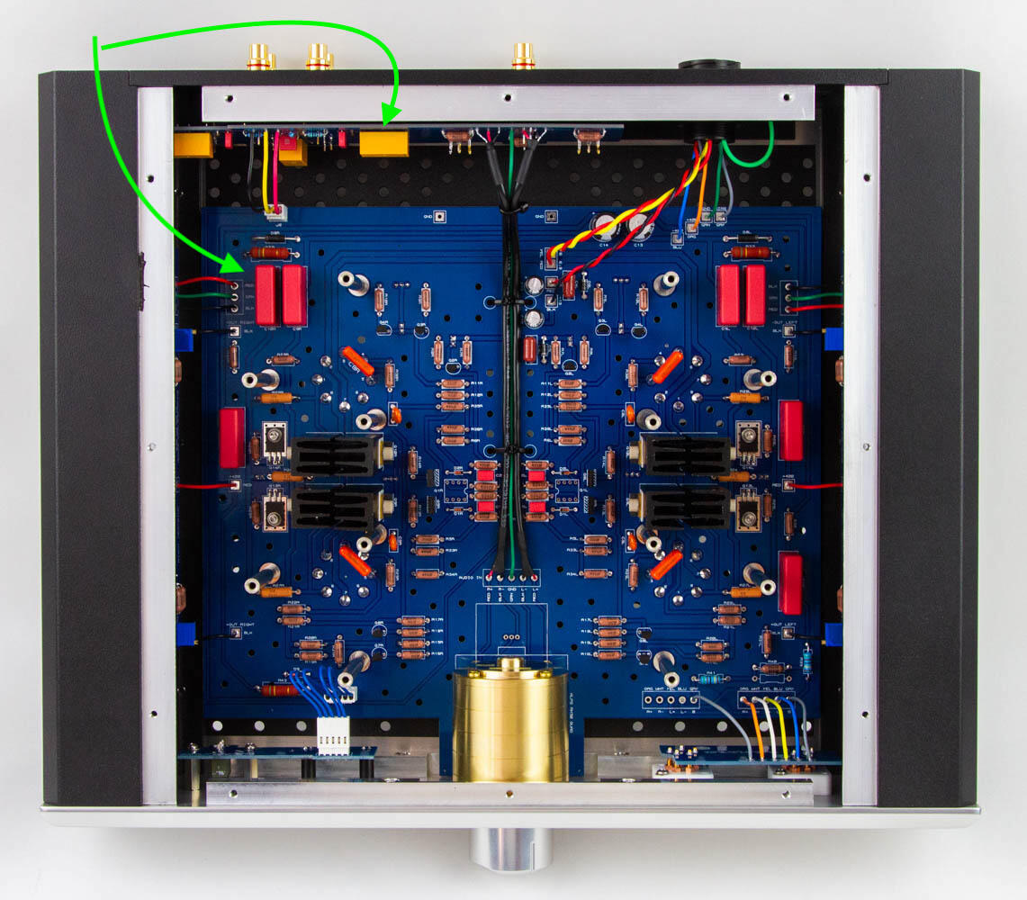
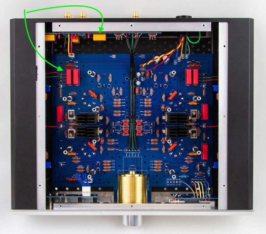
And one more quick question. After warming up, the amplifier begins to make noise. The noise is not loud. But clearly distinguishable, in the form of a continuous hissing/rustling sound. It's like water running through the pipes. I tried to cover the amp with a towel and found that the source of the rustling was to the right of the far right tube (as viewed from the front), towards the rear panel, near (but not beside) the RCA1 inputs. According to the photos, it could be a film capacitor (red)? Or something that looks yellow? I haven't opened the chassis yet, but I plan to figure it out myself and eliminate the annoying noise. The parcel with the amp went from USA to Germany something could be loose.... So, what to look out for?
-
Justin, hello and thank you! I understood. So the "run-up" is 43V. So now, basically, if after turning on the amplifier the offset is -43V, after 3 minutes — -28V, after 30 minutes — -15V, after 60 minutes — -5V, and after 90 minutes — 0V, there's no need to worry about it? Or would you recommend to adjust it so that the offset is, for example, -35V when power is applied, and +8V when it is fully warmed up? I'm not talking about sound quality. I am talking about observing the correct parameters that you have determined by your engineering thought.
-
And now the question. I decided to check the balance and offset. Regardless of whether the amplifier has just been turned on or has already been running for 2 hours, the balance between L+/L-, as well as between R+/R-, is always around 0V. When measuring the offset I was confused by the following: 1. After turning on the amplifier for the first time, the L+/GND value was -9V, and the R+/GND value was -11V. 2. As the amplifier warmed up, these values began to increase by about 1 volt over 3 minutes. 3. I left the amplifier to warm up and after 2 hours the L+/GND value was +20V, and the R+/GND value was +20V. Let me remind, that the balance between L+/L-, as well as between R+/R-, is always around 0V. It seemed strange to me that the offset values had such a wide spread and, by analogy with adjusting the STAX amplifiers, I adjusted the offset value to 0V. In short, after 4 hours of operating the amplifier, I achieved that both the balance and offset were around 0V. I connected the headphones and started listening to music and it was, as expected, great (impressions later). I turned off the amplifier and went to bed. In the morning I turned on the amplifier, after 10 seconds it SUDDENLY turned off. I realized that these are input fuses. And so it was - they burned. I replaced the fuses with new ones (back to 250V/1.6A for now) and the amplifier turned on successfully. I decided to check the offset again and found that L+/GND was -38V and R+/GND was -39V. After about an hour and a half, the values reached 0V. Actually, the question is: what should the offset value be when the amplifier is not warmed up and when it is warmed up?
-
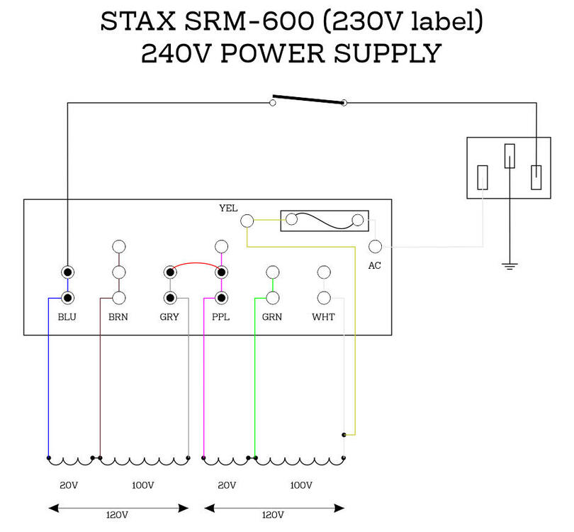
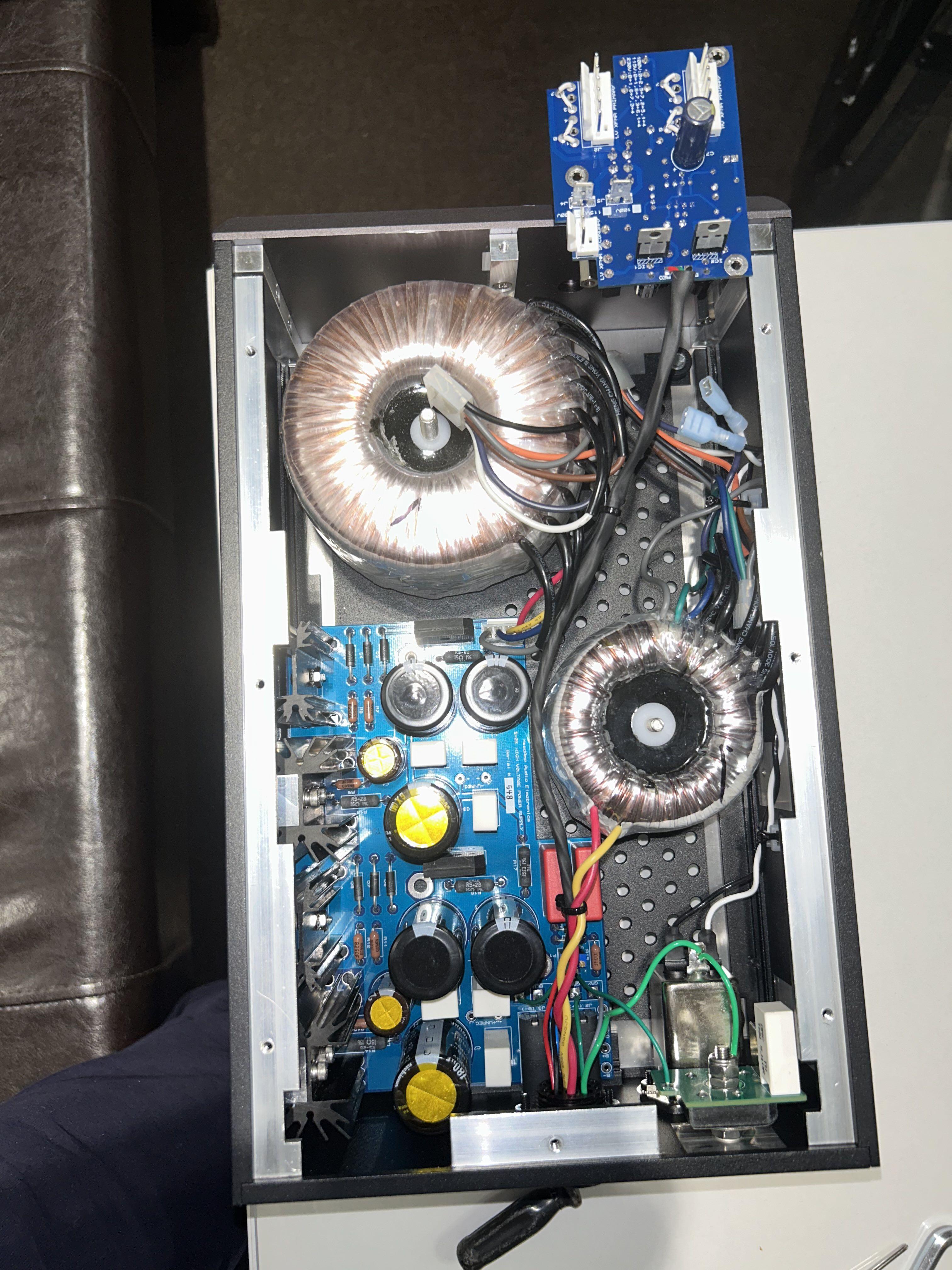
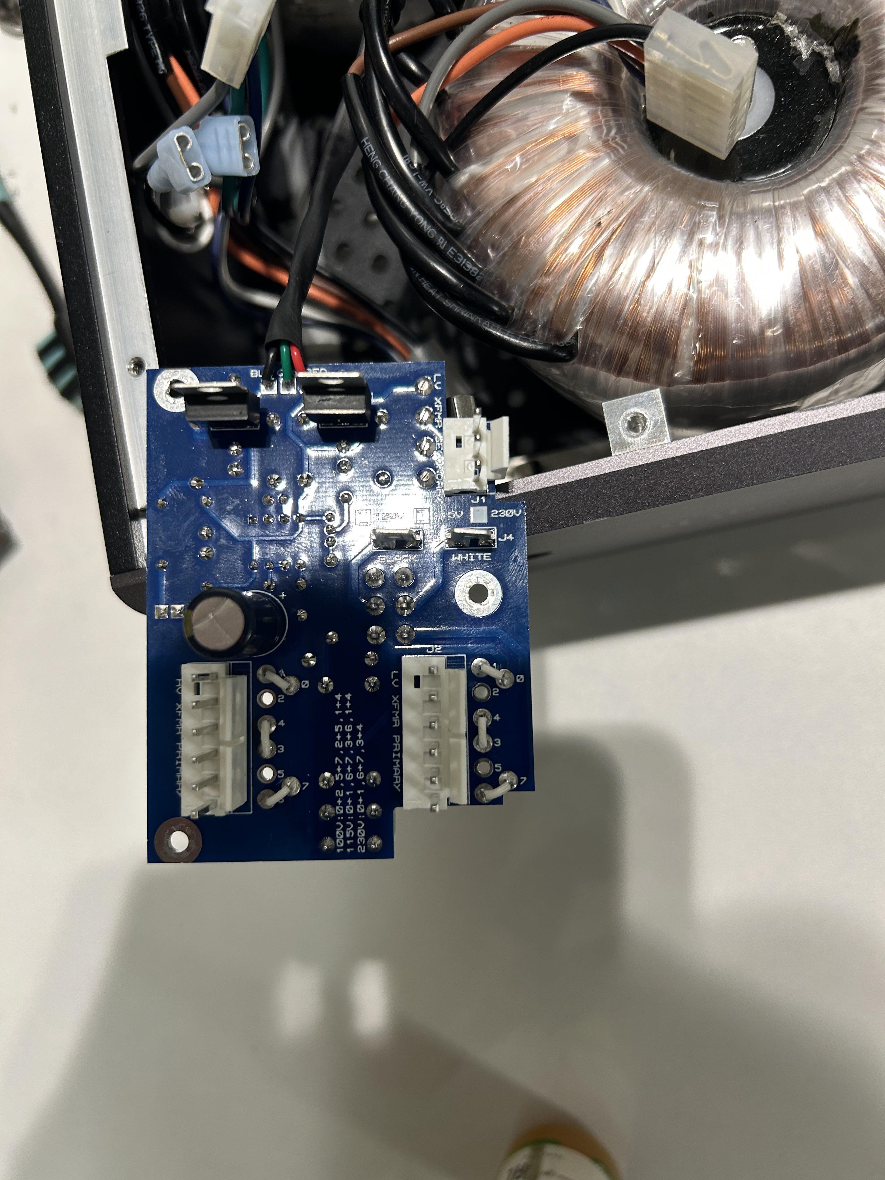
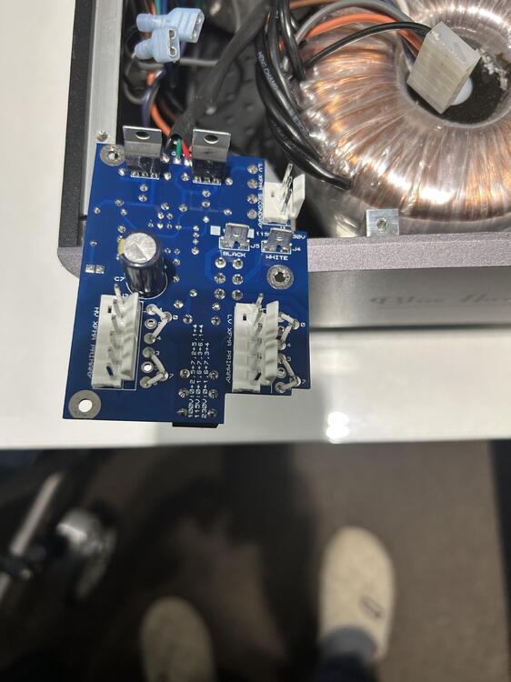
Progress report. I opened the PSU, took out the board: Jumpers before: Jumpers after: When replacing the incoming fuses, I was surprised to find that the 250 volt / 4 amp fuses were installed. I assumed they would be 3.15 amps, so I bought 1.6 amps for my 230V ones. I've put them in for now, although apparently I need to replace them with 250V/2A. Turned the amp on. It works!


-
Justin, you're amazing! I appreciate your friendly, open and caring attitude! After I get the amp, re-solder the pins in the PSU and verify operation, I will report back. Thank!
-
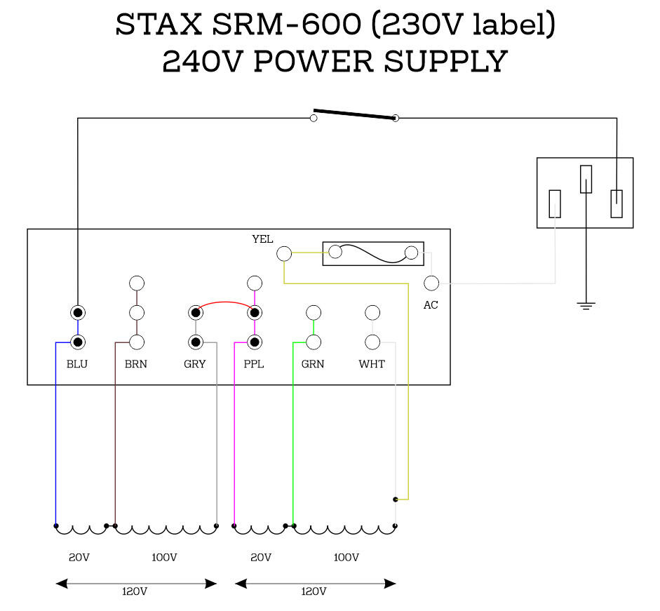
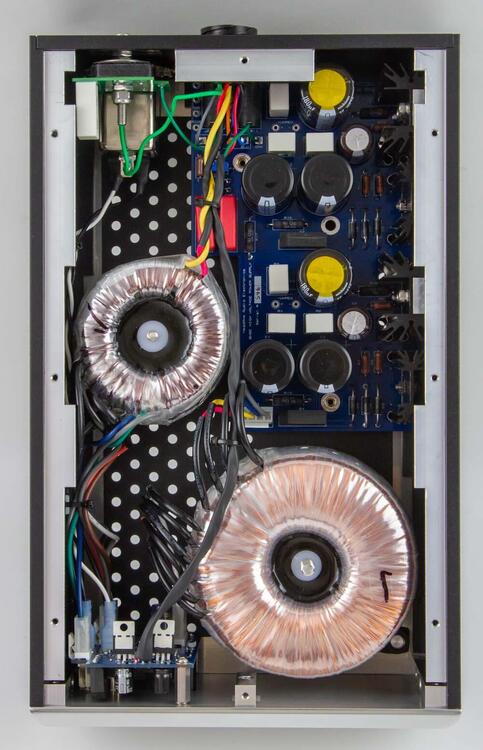
Friends, my compliments! Finally, in addition to my SRM-600 with CCS-mod (mr. Gilmore, every time I use the amplifier I mentally thank you!) after years of waiting i purchase a Blue Hawaii SE from a USA owner. Please can you give me hints on how to change the voltage for PSU? Need to change from 117 to 230V (Germany). I'd appreciate it!
-
Finished the experiment. First put a Panasonic EEUFS1C512L 16V/5100μF capacitor. It also warms up, about 55C. That is, the increase in voltage rating has not changed the situation. Then I put a Panasonic EEUFS1A752L 10V/7500μF. It is warmed up, but less, about 49C. That is, a 60% increase in capacitance rating led to a 10% decrease in temperature. Left 10V/7500μF, can no longer improve, 20000μF nowhere to place.
-
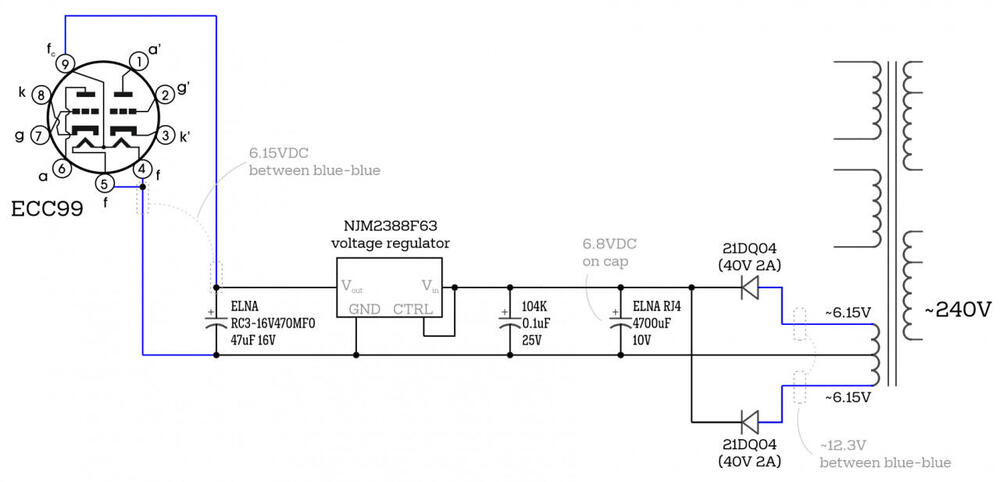
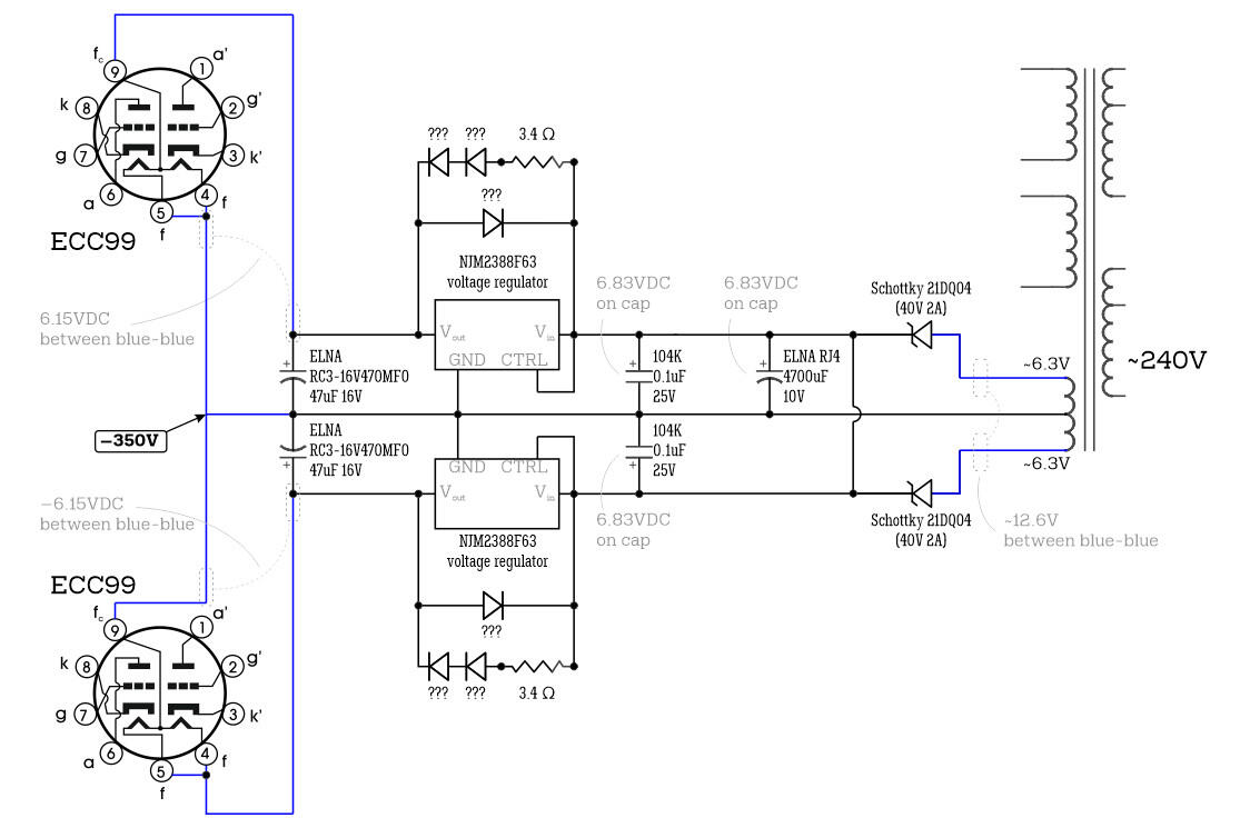
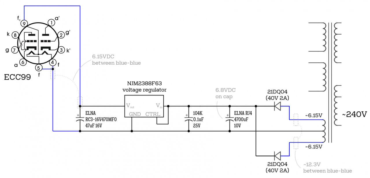
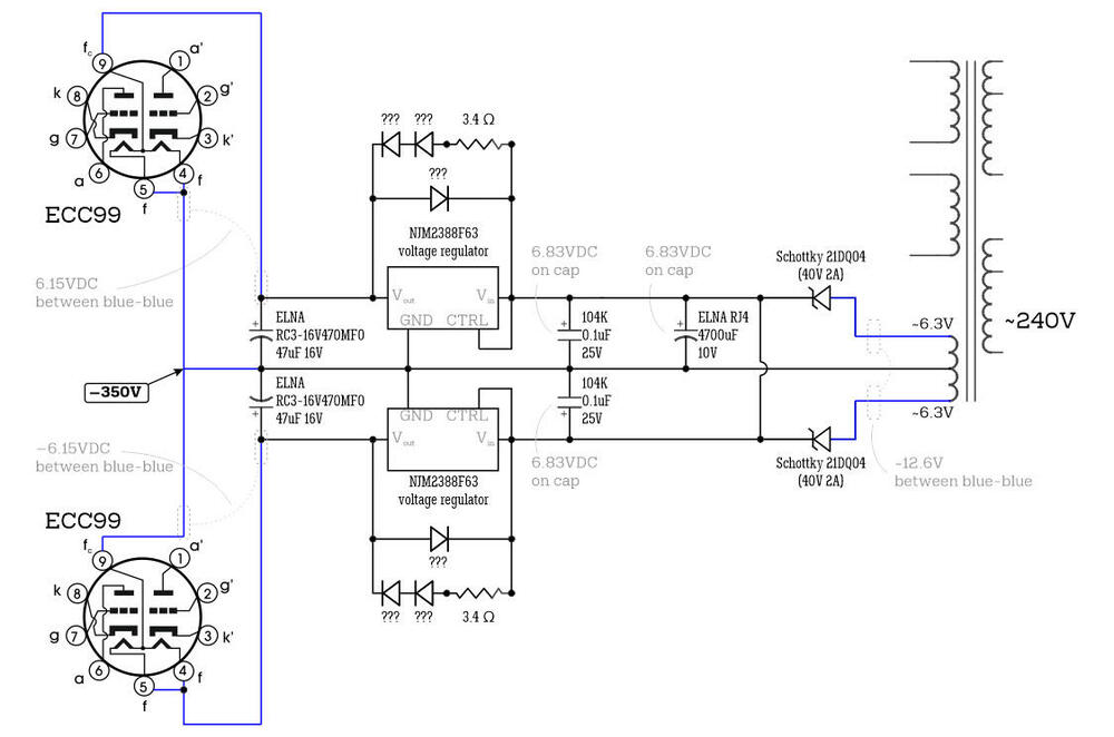
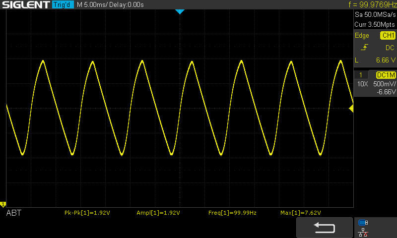
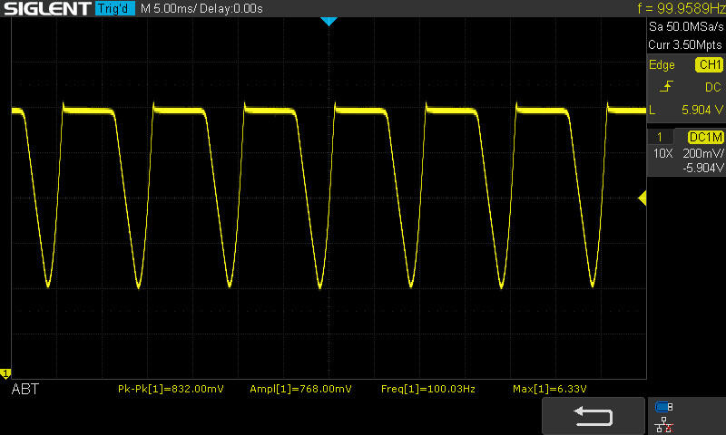
I'm still alive 🙂 and finally I found an oscilloscope. Up-to-date tube power supply circuit: I'm looking at a 4700µf/10V capacitor (where I previously measured 6.83 volts with a multimeter): The total pulsation is about 2 volts. Voltage (real) is 7.62 volts. I look at the leads to the tubes (where I previously measured 6.15 volts with a multimeter): That's 6.33 volts, all right. I draw a conclusion that the capacitor 4700µf/10V heating is a working design and so conceived by the manufacturer. I will try to replace it on Panasonic EEUFS1A752L 7500µf/10V.
-
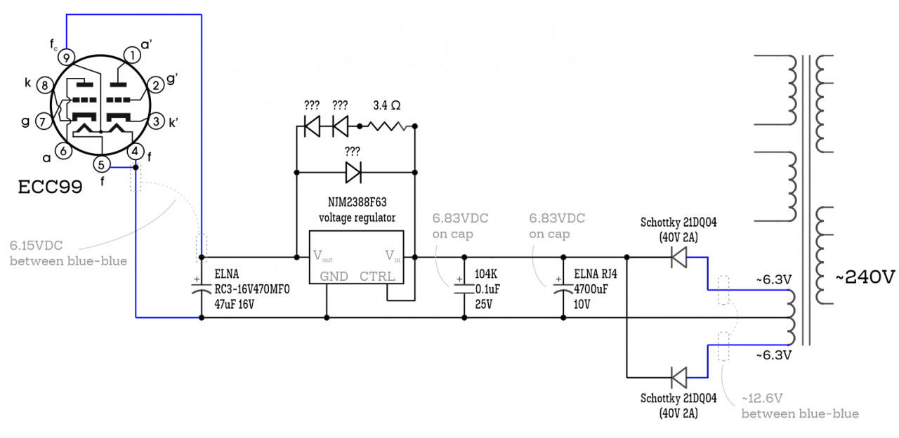
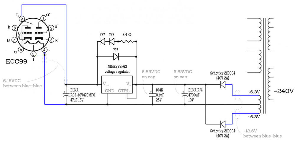
Up-to-date tube power supply circuit (around voltage regulator):
-
Addendum: Today (sunday evening), the power outlet has a 240VАС. I've again measured all voltages: - measured first blue to black (transformer) = 6.43VAC - measured second blue to black (transformer) = 6.43VAC - measured blue to blue = 12.86VAC - measured on the capacitor 4700uF/10V = 6.83VDC - measured at the tube filaments after the regulators = 6.15VDC That is, the diodes give stable 6.8VDC to 6.83VDC, and voltage regulators give stable 6.14 to 6.15VDC. That seems to be the design.
-
Clarifications: - It turns out that all the wings in the transformer are connected. Thus, it works at 240V. - The voltage in the power outlet is 230±5V (the input voltage fluctuates within 2-3%). - there is no AC-voltage on the tubes. Up-to-date tube power supply circuit: I can rewire the power supply to 220V.