# Stax
-
- 3 comments
- 918 views
-
- 5 comments
- 7009 views
-
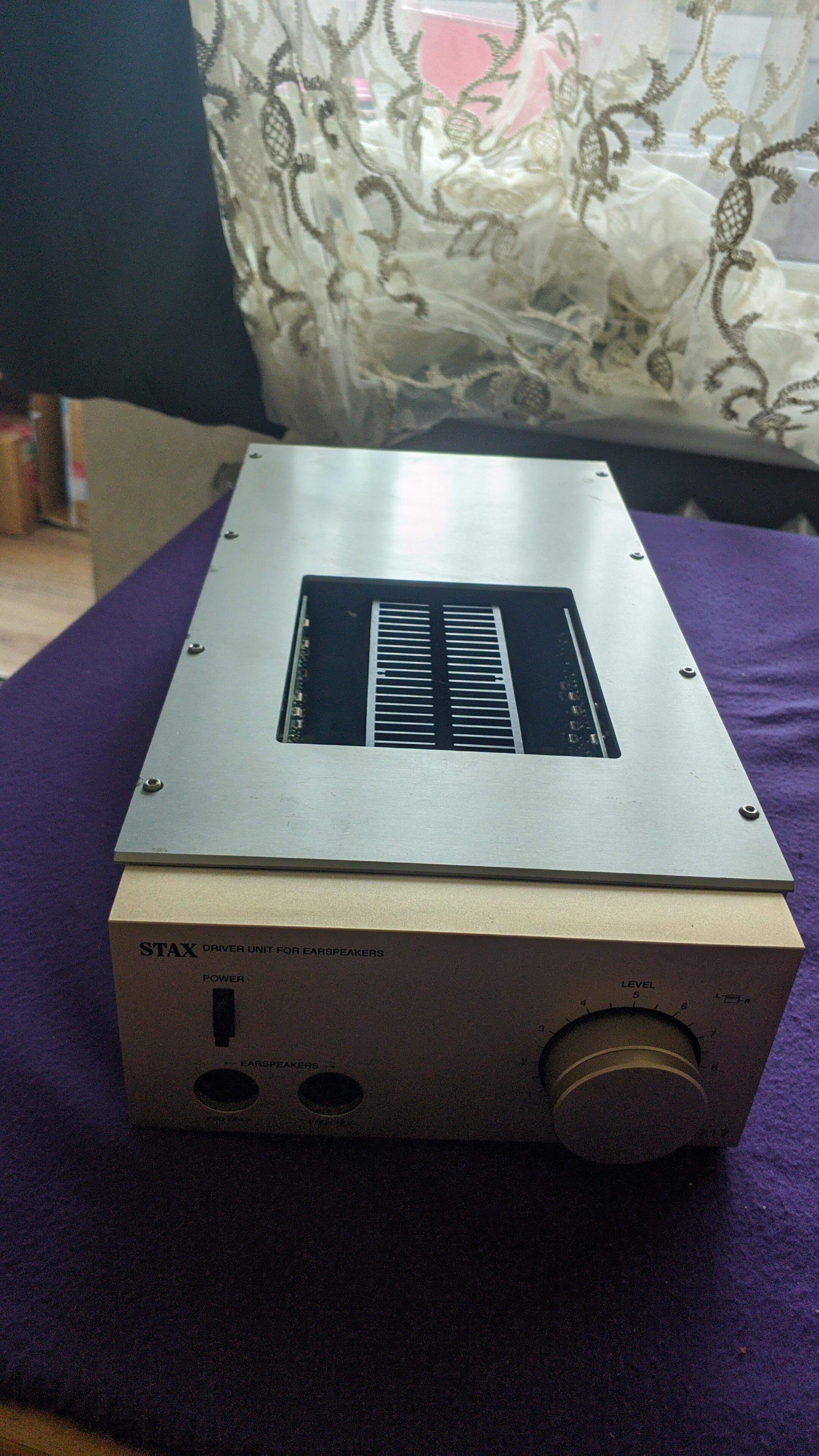
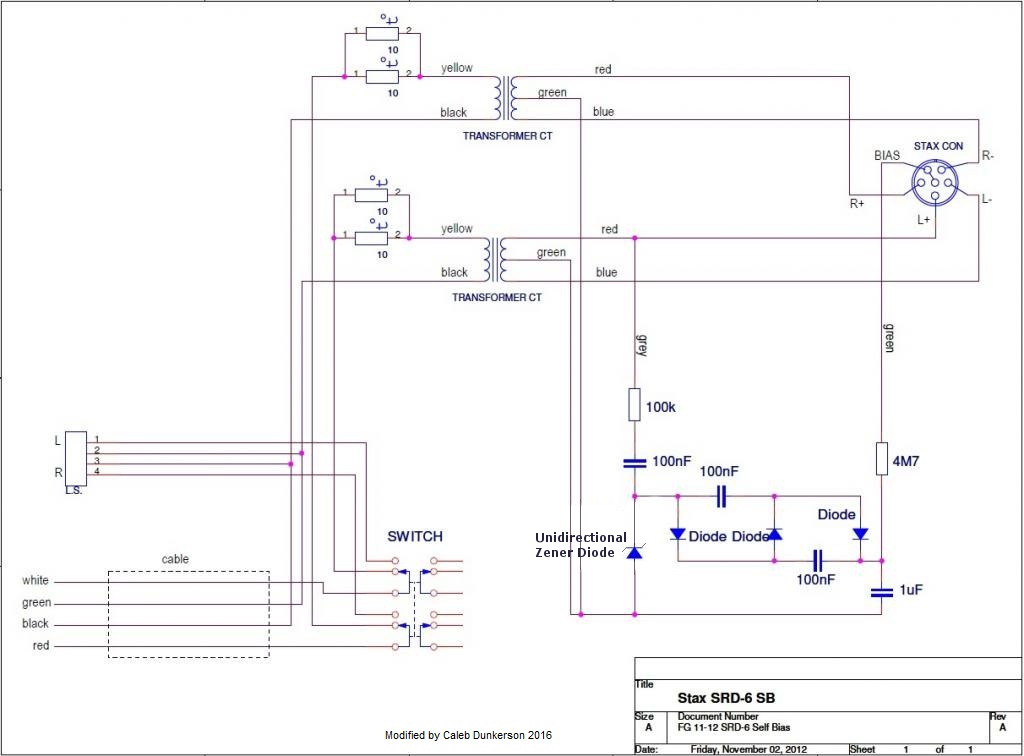
- stax
- srd-6
- self bias
- transformer
-
Tagged with:
- 31 comments
- 22416 views
-
- 108 comments
- 56621 views
-
- 34 comments
- 14476 views
-
- 25 comments
- 9211 views
-
- 1 comment
- 1382 views
-
- 257 comments
- 85415 views
-
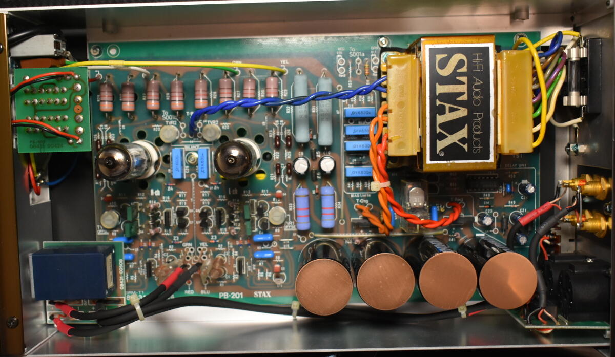
- stax
- kevin gilmore
- spritzer
- 006t
-
Tagged with:
- 36 comments
- 14047 views
-
- 48 comments
- 16999 views
-
- 4 comments
- 2530 views
-
- 24 comments
- 6979 views
-
- 19 comments
- 13748 views
-
- 4 comments
- 5112 views
-
- 8 comments
- 7874 views


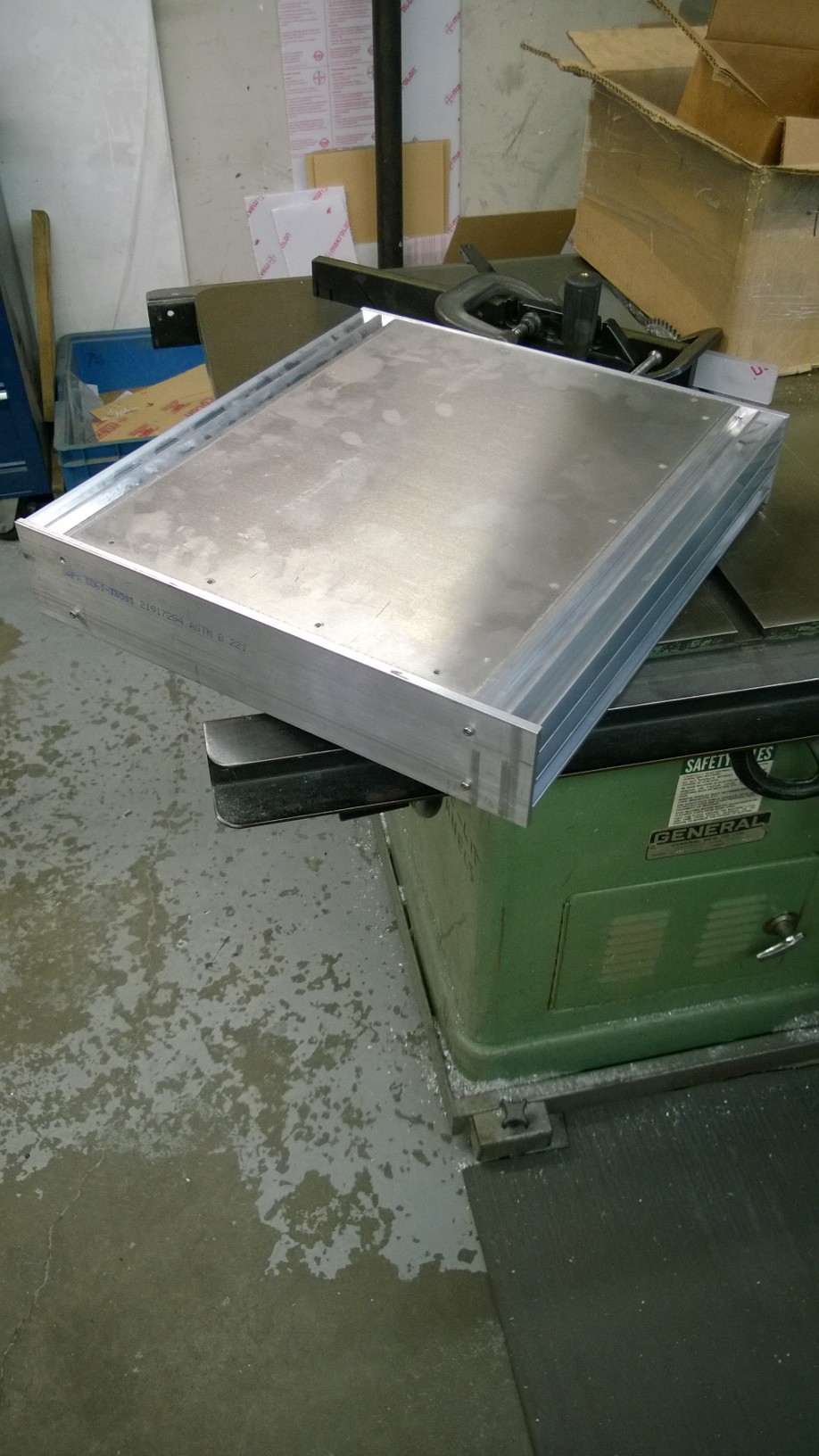
![[DIY Stax Tube Amp] Rolled the dice on an auction, what exactly did I just buy?](https://www.head-case.org/forums/uploads/monthly_2020_12/stax.jpg.ea3a14caadb034afb2b8c248a38d273f.jpg)


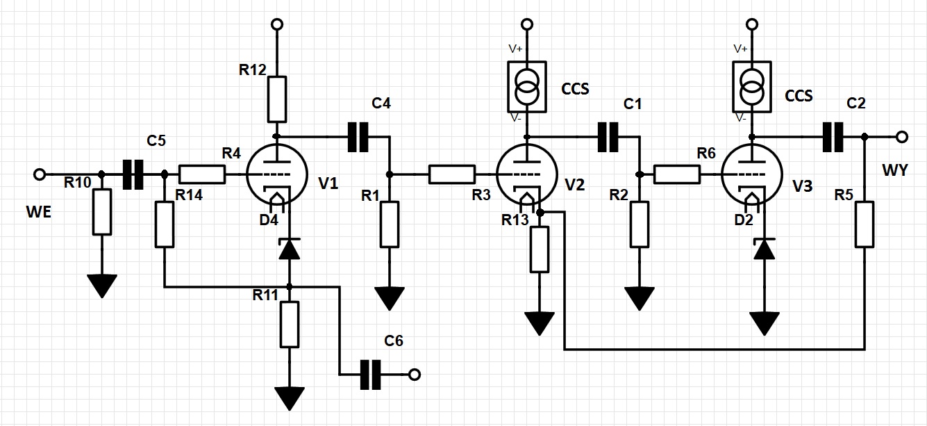
![Kevin Gilmore Circlotron Output, Large Enclosure [high-slew] Electrostatic Amplifier](https://www.head-case.org/forums/uploads/monthly_07_2015/post-3212-0-74125200-1435918289.png)


![[DT-HWT] electrostatic headphone tube Amplifier/Preamplifier](https://www.head-case.org/forums/uploads/monthly_2017_05/DT-HWT-amp-unit.jpg.cadc66ba990ee8c212817f9a3321e08e.jpg)