bdinnev
-
Posts
30 -
Joined
-
Last visited
bdinnev's Achievements
Advanced Member (3/6)
10
Reputation
-
and now for something completely different part 3
bdinnev replied to kevin gilmore's topic in Do It Yourself
Looks like I had better get the hot air gun and soldering iron out . . .
-
and now for something completely different part 3
bdinnev replied to kevin gilmore's topic in Do It Yourself
Yeah I did 2oz copper. Shipped for 5 pairs (split) boards (I know, 1 left over . . . . .) it came in at $135 - duties, sales tax etc . . . -
and now for something completely different part 3
bdinnev replied to kevin gilmore's topic in Do It Yourself
Last time I checked it was during COVID and the figures just didnt stack for small runs up so had not thought about it this time round - but have just placed an order to get a batch made so will have a few spares - have gone with the CFA3 split boards and a whole new set of components so fingers crossed in the next week or so I have 2 boards working successfully. -
and now for something completely different part 3
bdinnev replied to kevin gilmore's topic in Do It Yourself
HI All, After a long hiatus, I finally got back around to trying to spin up my CFA3 (rev 1.2) boards. After letting the magic smoke out of the output resistors a couple of times, replacing them, backtracking a few things / posts etc I finally got 1 side of one board to the reasonable point from both a dc offset and bias perspective without letting the magic smoke out. The other side of the board is still way off on DC offset (.4v) but nothing is smoking, so before I started probing that side of the board, I decided to plug my other one in to see where it was at. After backing off all the pots and then plugging it in, the output resistors immediately went nuclear on one side. I de-soldered them and I think the heat from the meltdown coupled with me de-soldering those resistors a few times now weakened the copper traces on the board and I have now lost a couple of pads on the output resistors. I know I could make a fairly simple repair to try and get it working at least for proof of concept but coupled with the other issues I am having with the board I think it may be time to start from scratch rather that de-soldering all the transistors etc on the board and swapping them out trying to find the core issue. Does anyone have any headphone boards they can sell? I would either look for a single replacement 1.2 board or look for a pair / quad (?) of later boards and make a new complete pair. If anyone can assist, please dm me. I am based in the US but happy to pay freight from OS if needs be. Cheers, Ben -
and now for something completely different part 3
bdinnev replied to kevin gilmore's topic in Do It Yourself
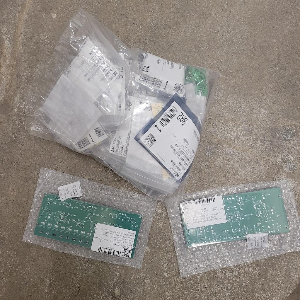
I will get probing soon and see what the results are. Is going to take me a little bit to make sense of the schematic and how it refers to the physical board but that is what learning is all about.... On the learning topic - not sure where the feedback resistors are. The boards are fully populated except for the 2 x surface mount resistors on the underside. Here is a picture - -
and now for something completely different part 3
bdinnev replied to kevin gilmore's topic in Do It Yourself
OK, a bit more testing. The previous tests I did were all with the SS jumpers in place. I have taken them off and jumped all the ZF jumpers and get some different results. In ZF mode, on the board that was reading -2.5v the DC offset comes down considerably - 145mv and -81mv @ ~150mA bias. On the other board that was measuring -500mv it still measures the same in ZF mode, however I need to adjust the 5k trim-pots a fair amount to get back to ~150mA bias - I think I saw a post a few pages back with a similar situation so will go back and read the thread again! -
and now for something completely different part 3
bdinnev replied to kevin gilmore's topic in Do It Yourself
All of the ones in both boards at present are the same (all purchased in one batch from Mouser), but I will try swapping them all out for the ones MLA mentioned above and see if it makes a difference - I am ordering all new PNP/NPN transistors (I think I ordered the batch I have at the height of COVID when stock was hard to come by and although everything else was sourced from Mouser, those may have come from somewhere less reputable) and some new resistors / capacitors to bump up the GRLV's to 30v so tacking on some LED's to the order won't make much of a difference in the scheme of things. -
and now for something completely different part 3
bdinnev replied to kevin gilmore's topic in Do It Yourself
I have noticed that the LED's on the -ve side of the board don't glow as bright as those on the +ve side of the board - is that normal or has anyone else noticed this in correlation with an issue? I will try changing the LED's and see what happens. -
That does not appear to be the same switch - the C&K is rated at 5A, not 6A, and the writing for the ON / ON is orientated differently. I have been able to find plenty of 5A rated switches, but no 6A.
-
Can anyone help identify who makes this toggle switch? I need to source a replacement as this one is broken but am struggling to find a 6A / 3A 125/250vac model
-
and now for something completely different part 3
bdinnev replied to kevin gilmore's topic in Do It Yourself
I have visually checked all the components on the boards and tested what I could with a meter and all seems OK - all resistors are in the correct location and of the correct values (as per the boards), all the caps seem to be in the correct orientation, all the PNP's and all the NPN's in the correct location, diodes etc, and the same across both boards. All the transistors are in the correct locations (15030 v 15031) and there does not smell or appear to have been any magic smoke come from anything. Is there anywhere on the board I can probe for a voltage / resistance to try and narrow down the issue? -
and now for something completely different part 3
bdinnev replied to kevin gilmore's topic in Do It Yourself
I am reading -500mv on one board with the 10k pot trimmed to the max (or min depending on how you look at it) , the other board is reading around -2.5v! Any ideas where to look? -
and now for something completely different part 3
bdinnev replied to kevin gilmore's topic in Do It Yourself
OK, will go across 1 resistor, makes the math easy Hopefully last question - what dc offset voltage should I be aiming for? My research leans towards "as close to 0+- as possible" as any voltage whilst "idle" simple gets turned into heat / noise on the transducers?? -
and now for something completely different part 3
bdinnev replied to kevin gilmore's topic in Do It Yourself
When I was getting all the parts some time ago, someone who has built one recommended I get 21v transformers, I actually ended up with 24v transformers. My understanding is that the output of the GRLV's will / should be lower than the input voltage so 20v seemed about right? Circa 150mA bias is what I have seen throughout this thread as well so seems to be on the money, my only question is is that when measuring across 1 of the 2 1ohm series resistors, or across both (mine read 2.3 ohm when measured across both on both the +ve and the -ve circuits). My measurements at present show a DC voltage of approx 150mv on both +ve and -ve after a quick tweak on the 5ohm pots, however the voltages are not stable, they are consistently rising (they are not oscillating, just increasing), the rising does slow down after a few minutes, but they do continue to go up - caused by temp increase across the circuit? If the measurement is across 1 or the 2 series resistors, then 150mv will be circa 150mA, but if I need to measure across both resistors in series, then I need to bump up the bias by double - a considerable increase. -
and now for something completely different part 3
bdinnev replied to kevin gilmore's topic in Do It Yourself
Thanks Pars - I dialed in the GRLV's many moons ago, they are both running at 19.995v +- .002 on all outputs. When you say "across the 1ohm resistors" - is that across 1 of them, or across the pair on each circuit? I have the protector board ready to wire in, that will happen as part of the casing process, just want to get the CFA3 boards sorted ATM, one step at a time Thanks, Ben