bdinnev
-
Posts
30 -
Joined
-
Last visited
Content Type
Profiles
Forums
Events
Everything posted by bdinnev
-
and now for something completely different part 3
bdinnev replied to kevin gilmore's topic in Do It Yourself
Looks like I had better get the hot air gun and soldering iron out . . .
-
and now for something completely different part 3
bdinnev replied to kevin gilmore's topic in Do It Yourself
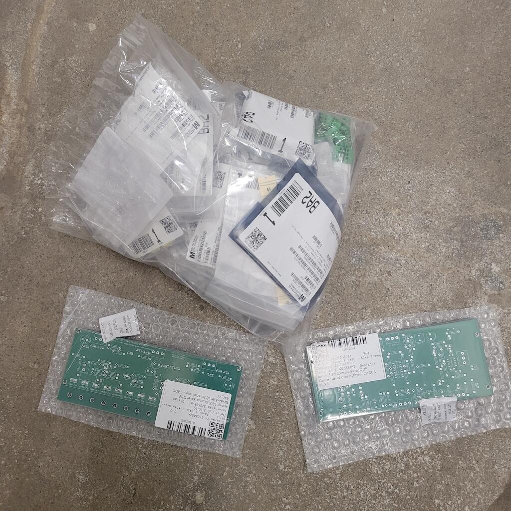
Yeah I did 2oz copper. Shipped for 5 pairs (split) boards (I know, 1 left over . . . . .) it came in at $135 - duties, sales tax etc . . . -
and now for something completely different part 3
bdinnev replied to kevin gilmore's topic in Do It Yourself
Last time I checked it was during COVID and the figures just didnt stack for small runs up so had not thought about it this time round - but have just placed an order to get a batch made so will have a few spares - have gone with the CFA3 split boards and a whole new set of components so fingers crossed in the next week or so I have 2 boards working successfully. -
and now for something completely different part 3
bdinnev replied to kevin gilmore's topic in Do It Yourself
HI All, After a long hiatus, I finally got back around to trying to spin up my CFA3 (rev 1.2) boards. After letting the magic smoke out of the output resistors a couple of times, replacing them, backtracking a few things / posts etc I finally got 1 side of one board to the reasonable point from both a dc offset and bias perspective without letting the magic smoke out. The other side of the board is still way off on DC offset (.4v) but nothing is smoking, so before I started probing that side of the board, I decided to plug my other one in to see where it was at. After backing off all the pots and then plugging it in, the output resistors immediately went nuclear on one side. I de-soldered them and I think the heat from the meltdown coupled with me de-soldering those resistors a few times now weakened the copper traces on the board and I have now lost a couple of pads on the output resistors. I know I could make a fairly simple repair to try and get it working at least for proof of concept but coupled with the other issues I am having with the board I think it may be time to start from scratch rather that de-soldering all the transistors etc on the board and swapping them out trying to find the core issue. Does anyone have any headphone boards they can sell? I would either look for a single replacement 1.2 board or look for a pair / quad (?) of later boards and make a new complete pair. If anyone can assist, please dm me. I am based in the US but happy to pay freight from OS if needs be. Cheers, Ben -
and now for something completely different part 3
bdinnev replied to kevin gilmore's topic in Do It Yourself
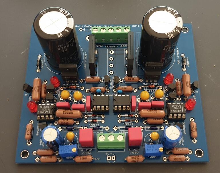
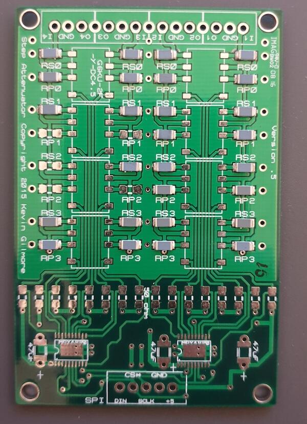
I will get probing soon and see what the results are. Is going to take me a little bit to make sense of the schematic and how it refers to the physical board but that is what learning is all about.... On the learning topic - not sure where the feedback resistors are. The boards are fully populated except for the 2 x surface mount resistors on the underside. Here is a picture - -
and now for something completely different part 3
bdinnev replied to kevin gilmore's topic in Do It Yourself
OK, a bit more testing. The previous tests I did were all with the SS jumpers in place. I have taken them off and jumped all the ZF jumpers and get some different results. In ZF mode, on the board that was reading -2.5v the DC offset comes down considerably - 145mv and -81mv @ ~150mA bias. On the other board that was measuring -500mv it still measures the same in ZF mode, however I need to adjust the 5k trim-pots a fair amount to get back to ~150mA bias - I think I saw a post a few pages back with a similar situation so will go back and read the thread again! -
and now for something completely different part 3
bdinnev replied to kevin gilmore's topic in Do It Yourself
All of the ones in both boards at present are the same (all purchased in one batch from Mouser), but I will try swapping them all out for the ones MLA mentioned above and see if it makes a difference - I am ordering all new PNP/NPN transistors (I think I ordered the batch I have at the height of COVID when stock was hard to come by and although everything else was sourced from Mouser, those may have come from somewhere less reputable) and some new resistors / capacitors to bump up the GRLV's to 30v so tacking on some LED's to the order won't make much of a difference in the scheme of things. -
and now for something completely different part 3
bdinnev replied to kevin gilmore's topic in Do It Yourself
I have noticed that the LED's on the -ve side of the board don't glow as bright as those on the +ve side of the board - is that normal or has anyone else noticed this in correlation with an issue? I will try changing the LED's and see what happens. -
That does not appear to be the same switch - the C&K is rated at 5A, not 6A, and the writing for the ON / ON is orientated differently. I have been able to find plenty of 5A rated switches, but no 6A.
-
Can anyone help identify who makes this toggle switch? I need to source a replacement as this one is broken but am struggling to find a 6A / 3A 125/250vac model
-
and now for something completely different part 3
bdinnev replied to kevin gilmore's topic in Do It Yourself
I have visually checked all the components on the boards and tested what I could with a meter and all seems OK - all resistors are in the correct location and of the correct values (as per the boards), all the caps seem to be in the correct orientation, all the PNP's and all the NPN's in the correct location, diodes etc, and the same across both boards. All the transistors are in the correct locations (15030 v 15031) and there does not smell or appear to have been any magic smoke come from anything. Is there anywhere on the board I can probe for a voltage / resistance to try and narrow down the issue? -
and now for something completely different part 3
bdinnev replied to kevin gilmore's topic in Do It Yourself
I am reading -500mv on one board with the 10k pot trimmed to the max (or min depending on how you look at it) , the other board is reading around -2.5v! Any ideas where to look? -
and now for something completely different part 3
bdinnev replied to kevin gilmore's topic in Do It Yourself
OK, will go across 1 resistor, makes the math easy Hopefully last question - what dc offset voltage should I be aiming for? My research leans towards "as close to 0+- as possible" as any voltage whilst "idle" simple gets turned into heat / noise on the transducers?? -
and now for something completely different part 3
bdinnev replied to kevin gilmore's topic in Do It Yourself
When I was getting all the parts some time ago, someone who has built one recommended I get 21v transformers, I actually ended up with 24v transformers. My understanding is that the output of the GRLV's will / should be lower than the input voltage so 20v seemed about right? Circa 150mA bias is what I have seen throughout this thread as well so seems to be on the money, my only question is is that when measuring across 1 of the 2 1ohm series resistors, or across both (mine read 2.3 ohm when measured across both on both the +ve and the -ve circuits). My measurements at present show a DC voltage of approx 150mv on both +ve and -ve after a quick tweak on the 5ohm pots, however the voltages are not stable, they are consistently rising (they are not oscillating, just increasing), the rising does slow down after a few minutes, but they do continue to go up - caused by temp increase across the circuit? If the measurement is across 1 or the 2 series resistors, then 150mv will be circa 150mA, but if I need to measure across both resistors in series, then I need to bump up the bias by double - a considerable increase. -
and now for something completely different part 3
bdinnev replied to kevin gilmore's topic in Do It Yourself
Thanks Pars - I dialed in the GRLV's many moons ago, they are both running at 19.995v +- .002 on all outputs. When you say "across the 1ohm resistors" - is that across 1 of them, or across the pair on each circuit? I have the protector board ready to wire in, that will happen as part of the casing process, just want to get the CFA3 boards sorted ATM, one step at a time Thanks, Ben -
and now for something completely different part 3
bdinnev replied to kevin gilmore's topic in Do It Yourself
Hi All, As with most of us, "life" caused some delays with my CFA3 build and I am just getting back around to trying to finish it off. I have 2 x GRLV's and 2 x CFA3 boards ready to go, just need to get initial setup done and then will case it all up. I have got the general idea of initial setup steps but is anyone able to assist with a step by step guide for a CFA3 - I.E. what do you do when powering up the first time? I understand I need to pull the op-amps out, power a board up and adjust trim-pots for bias, but can anyone help with where I should be measuring and what I should be aiming for, what steps should be taken and what safety measurements should be taken to ensure everything is functioning correctly? Thanks! Ben -
Thanks audiostar. Yes, the transistors on the GRLV's will be mounted on the heatsinks on the side of the case - I temporarily soldered them into the boards just so I could do some quick tests on the GRLV's to make sure there was not any unwanted smoke etc but will remove the transistors and then re-mount them onto some aluminum angle which will then be mounted to the case heatsinks and solder them back into the boards. I have a headphone protector board ready to go as well as a pair of the 1st gen digital attenuators and a ss / zf switcher board. I am going to be running 3 transformers in the PSU - 2 x 24v 100va for the GRLV's and 1 x 15v 50va a to run the headphone protector, DA's, DA controller and ss / zf switcher along with 2 linear power circuits for 12v and 5v. I know it is a bit of overkill but I have space for it so figured why not. I need to go back and read the main thread for the CFA's to wrap my head around adjustment as it has been a while since I started this project. I will hopefully have the case for it in the next couple of weeks and once it is all cased up will get around to adjustments etc.
-
Finally received the last of the components for the CFA boards today from DigiKey - Mouser who I usually use were out of a couple of items and whilst DigiKey had the values I needed, they didnt have them in RN60 so ended up going for the slightly more expensive CMF series resistors - was only for a few values so was not a big deal and am happy to have everything in now. Some quick soldering and the CFA3 boards are finished (except for the output transistors - they will go in when I have the cases and heat-sinking sorted out) - has been a long time between start and finish but I can feel the end of this build getting near. PS, managed to find a free way to host images - Google Firebase - so can now insert images without having to worry about chewing up quota
-
I think the MJL* versions are the same except for different leg / pin sizes and slightly different packaging. Electrically they are the same as the MJW* (I think from memory)
-
Has been a bit of a while between updates on this one - I got a bit sidetracked with things to say the least! I finally pulled my finger out a few weeks back and got back onto this project. It has been fun trying to source parts in the current climate but I have managed. I am frustratingly close to getting the main components finished - I have 2 (actually 4 now) GRLV's built, all running within .005v of each other and each rail and I also have the majority of the 2 x CFA3 boards finished. I stuffed up on my last mouser order and ordered 300k Ohm resistors instead of 300 Ohm resistors - the downside to ordering things late at night! I also forgot to order a couple of other resistors so as it stands at present, I am about 6 resistors per board away from having the CFA boards complete. I also have the v1 digital attenuator boards finished and ready to go so that leaves the protector board and the ZF / SS board to go which should be pretty straight forward (although the relays for the switching board are getting hard to obtain). I also need to build a seperate power board for the ancillaries - the attenuators, motorised pot to control the attenuators and the switching board all require a combination of 12v, 5v and 3.3v so I think I am going to build a L-Adapter power supply to supply 12v to feed the relays and also feed that into a voltage reg circuit I have built myself for the 5v and 3.3 for the rest of things. It means I will have 3 power supplies in the PSU case along with 3 transformers etc but hey-ho. I have pretty much settled on the Takachi HY series enclosures for the PSU and Amp chassis - whilst I can fit the PSU in a slightly smaller footprint than the amp, I have decided to get them both in the same footprint just different heights - taller for the PSU and shorter for the amp / attenuator / pot / switching. They are not the cheapest chassis out there but not much more than most of the other options and a bit higher quality looking in my opinion. It would appear that my account is only allowed to post another 116kb in images to this thread so it is not possible to post any pics but will post an update in the next week or so once the boards are complete. Update - managed to sort out a way to host images so I can now insert them without worrying about quota - this is the chassis I am looking at going with (minus the UpTone Audio stuff....) -
-
Well spotted. Went back and checked what I ordered, and yes, RN65's - RN60's were not available for those 3 items . It does say on the spec for each item that they are physically larger, I just missed it at the time, I looked at resistance and wattage and figured same same at the time. I think I was swimming in BOM's with GRLV, CFA and 2 versions of DA to build a list for that I was getting a bit cross-eyed late in the night and missed it.
-
There is an issue with the 10k, 500R, and 2k resistors. They are all too big for the hole spacing. Interestingly, I just rechecked the BOM you posted on the gold reference thread back in April and it lists all 1/4w resistors, so not sure what has happened here. Looking a bit deeper, for the values where I could not get a direct hit on part number, I moved to 25ppm (default was 100ppm), same series (RN) same resistance and same wattage (1/4w) but guess the lower ppm results in a larger body which I had not paid attention to. Live and learn . . .
-
The main issue was that the resistors were longer than the hole spacing so the leads need to tuck back in to fit - I could have placed the resistors vertical and had the leads hook back over. I still need to order parts for the 2nd GRLV so may order some different resistors as part of that order and swap them out.
-
A little more progress - have the first or 2 GRLV's 98% done (at least until I figure out casing and heatsinks) Mouser were out of a couple of the default resistors so I had to change a couple to higher power (1/4w) which has resulted in a cramped fit for a couple of them but nothing too bad.
-
I had some parts left over and thought what the heck, I might as well do what I can on the v2 board. I was short a few of the resistors I had so need to get a few extras as well as a few other bits and pieces that differ between the v1 and v2 boards, then need to decide which one I will use - I like the form factor of the v2 board. After my first couple of hours with the heat gun I have to say I dont mind doing SMD work this way. Once you get some heat into the board the process goes pretty smoothly and the components just latch in to place which is nice. Now I need to start getting some components together for the GRLV and CFA boards and will then get to work on them.