GGW
-
Posts
19 -
Joined
-
Last visited
Content Type
Profiles
Forums
Events
Everything posted by GGW
-
Excellent post, James - thank you!!
-
@starcat @Pars - thanks a ton. Immensely helpful as always!
-
and now for something completely different part 3
GGW replied to kevin gilmore's topic in Do It Yourself
Hi guys, Is the "protect3.zip" the headphone protector gerber that is used in some of the CFA3's posted here? Does anyone have any leads on where I can find out more (Gerbers, BOMs, reading material) on the ZF / SS selector? Thanks! -
and now for something completely different part 3
GGW replied to kevin gilmore's topic in Do It Yourself
Thanks, @starcat - very helpful. Do you know where I can find the Gerbers for the ZF/SS selector and the headphone protector? -
and now for something completely different part 3
GGW replied to kevin gilmore's topic in Do It Yourself
Ah Awesome! @Kerry @kevin gilmore - what would you gents consider to be the ultimate overkill build for this CFP/A? 4x CFA2 boards or 2x CFA3 boards in 2 separate chassis, with 2 separately enclosed GRLV psu? Or is this new SMD animal you have designed the way to go, assuming the same multiple separate chassis & PSU overkill plan? Separately, I've read the entire thread and can't seem to get my head around the difference between using 4x CFA2 boards or 2x CFA3 boards - are there additional PCBs that need to be printed if I go the 4xCFA2 route (scheming going down this road and 2 dissipante cases such that each pcb has its own heatsink). Or do I just wait and go for the SMD boards you're working on? Many thanks in advance for the help and guidance Cheers -
and now for something completely different part 3
GGW replied to kevin gilmore's topic in Do It Yourself
What on earth is this now? Looks epic -
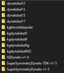
Thanks, @jamesmking - very helpful. I've read this entire thread and there are 3 updates to the version .45 board (see file names including the version on the silkscreen, in the snip below): For context, the descriptions Kevin uploaded with each: version 0.46 "rflip" because soren is running the grlv supply at 4.5 amperes, here is a new version with the feedback resistor locations flipped so that the sense is not one inch away from the output connector. sense is now tied directly to the inner power supply connector. So the 20mv change in voltage due to current should be completely canceled out. for higher currents, best if the board is made with 3 oz copper. version 0.47 "rflip to220" here is the version with the to220 sic diodes, someone really needs to check this version 0.48 "largecap" same size board, up to 35mm caps, had to move the pass transistors, needs checking silicon carbide rectifiers 100mm x 109mm I think @Pars mentioned the v0.48 is basically the v.45(?) with fatter, shorter (?) caps for when height is a constraint - is that correct? ******* My questions - (1.) are these all improvements (is version 0.48 the best in all use cases?) or are each of versions 0.46-0.48 just tweaks for specific use cases ? (2.) Which board is best suited to (a.) power the SS Dynalo (mk2 "multiamp"); and (b.) power balanced CFA boards (i.e. 2x CFA2 or 1x CFA3? Many thanks as always for the guidance! (For context - I'm trying to pull the trigger once on a PCB order, so trying to figure out the right versions of all the boards I need to avoid multiple shipping charges... i.e. GRLV, Dynalo, CFA2 or CFA3, etc.)

-
Hi Gents, 1.) Please could someone point me in the direction of the version .47 of the GRLV board? I can't see it on the share drive 😕 Separately, I have 2 additional questions if anyone could please help me: 2.) What is the latest / greatest / preferred GRLV version for each of the Dynalo and CFA2 x 4 (dual / balanced craziness; or 2 x CFA3 boards) ? 3.) I noticed there is another little PCB called "GR78xx" - would I need to get a few these printed as well? Or is it optional? If optional, what's the benefit? Thanks in advance for the guidance!!
-
Thank you, Kevin! Indeed that's exactly what I'm after
-
Can anyone advise on removing the little PCB at the bottom of the kgdynalobal_v9 Gerber file? jlcpcb.com asked me to remove it to avoid errors and I haven't a clue... Is there a version without the little PCB at the bottom?
-
@Pars you are a champion. Thanks a ton!
-
Cheers, Pars - will go swim through the Dynalobal gerbers until I find it
-
Thanks everybody - super helpful! @Pars - how did you hook up the LSK489 / LSJ689's to the THAT340 dip socket? Bending like crazy?
-
Noob question but do you have to match across N and P channels for the input stage? Or just within N and within P if you go the single JFET route? I.e. if I go for, say, 2 x LSJ74 and 2x LSK170 - do they ALL have to be matched or only the 74s with each other and the 170s with each other? If the latter, then no need to buy plenty LSK489 / LSJ689 and match them? Thanks!
-
thanks all! Does anyone have gerbers for the little adapter board to make the LS 170/74 JFETs work? And gerber for adapter board for LSK489 / LSJ689 please
-
Thanks, @starcat 🤘 Does anyone have any leads on LSJ109? (Side question, the LSJ109 doesn't look like a dual JFET so would I need a matched pair of these to replace a single 2SJ109?)
-
Thanks, Pars! Very much appreciated! 😬 Was quietly hoping you would respond as you have clearly tinkered more than anyone else on the thread when it comes to transistors used for the input stage
-
Hi All, After reading this entire thread, it seems there are a number of options for transistors to use in place of THAT340 on the input stage (if you can source them). Please could someone help rank the below in order of preference? - 2SJ109 / 2SK389 appear impossible to source - LSJ109 / LSK389 (LSJ109 also looks hopeless unless you roll the dice on ebay / aliexpress) - 2x Matched pairs of LSJ74 and LSK170 - 2SC3381 / 2SA1349 - LSK489 / LSJ689 - Anything else? Or just go with THAT340 and live with the low input impedance that seems to be a minor issue? Thanks!
-
Hi Youwin0125 I'm also new to the forum and with KG's help I found the share drive below with all the gerber files: ** LINK REMOVED ** GILMORE CAN POST IT IF HE WANTS ** There are a ton of Dynalo zips in there... no clue which is the latest and greatest! 😕