dsr33
Members
-
Joined
-
Last visited
-
Mission accomplished. All seems to be working fine after the modification. Just to confirm - there should be 3 red leds ON when the device is in working state (couple of D3s and a D4), correct? And again, is it advisable to go through readjusting the bias after the 100V-240V conversion? Unit is ~ 6 years old, tubes are RCA cleartops with a run time of ~ 150h, capacitors - I have no idea.
-
About the fuse, I meant if it being 1.6A can cause any electrical issues after the voltage change (think someone mentioned 1A fuse on his). And about the measurements - although I doubt that soldering was done incorrectly, but still, are there any precautionary measurements that I can make in order to be 100% sure that all's fine prior plugging it in? Spitzer, thanks a lot for helping out, really appreciate it!
-
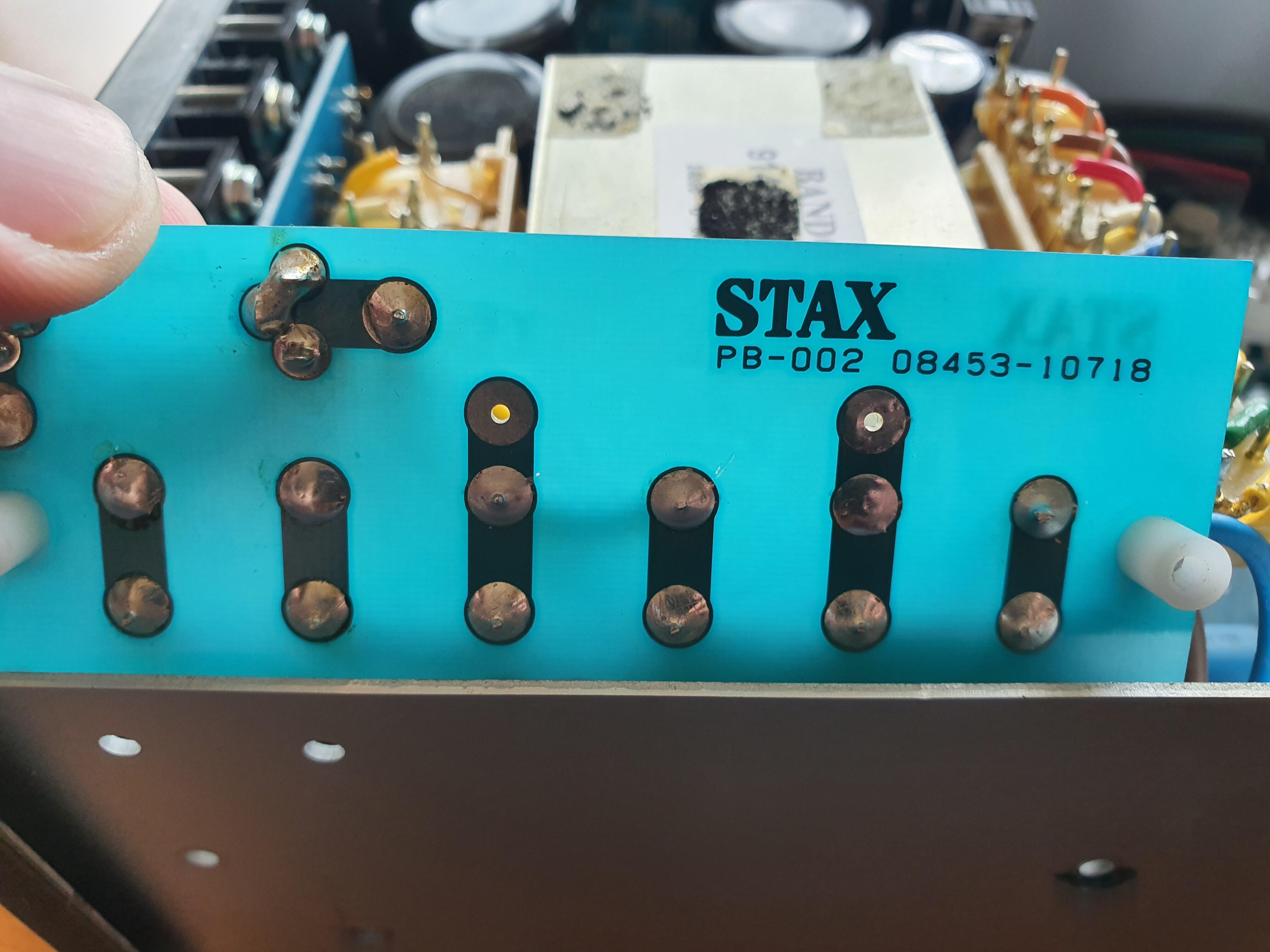
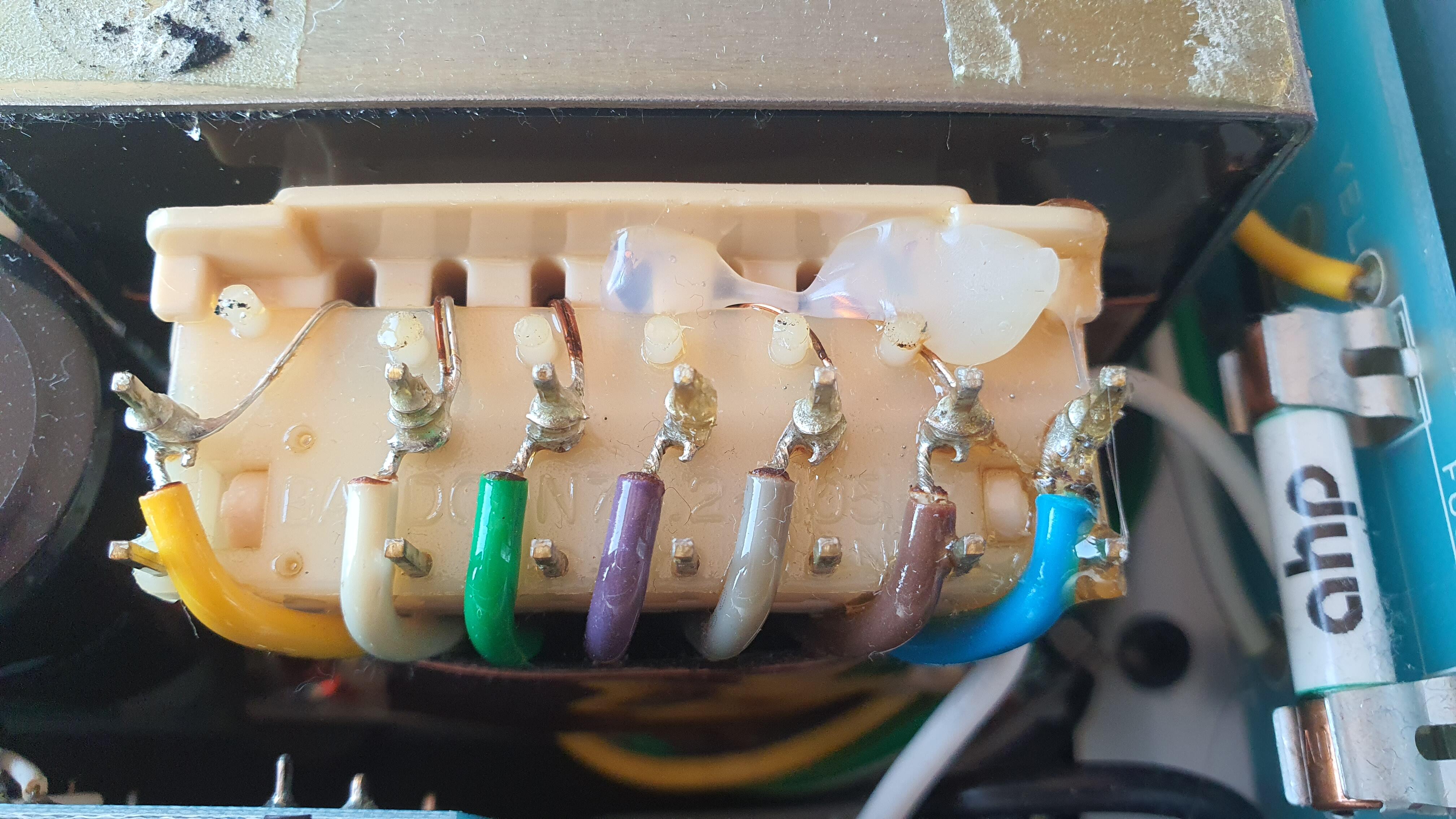
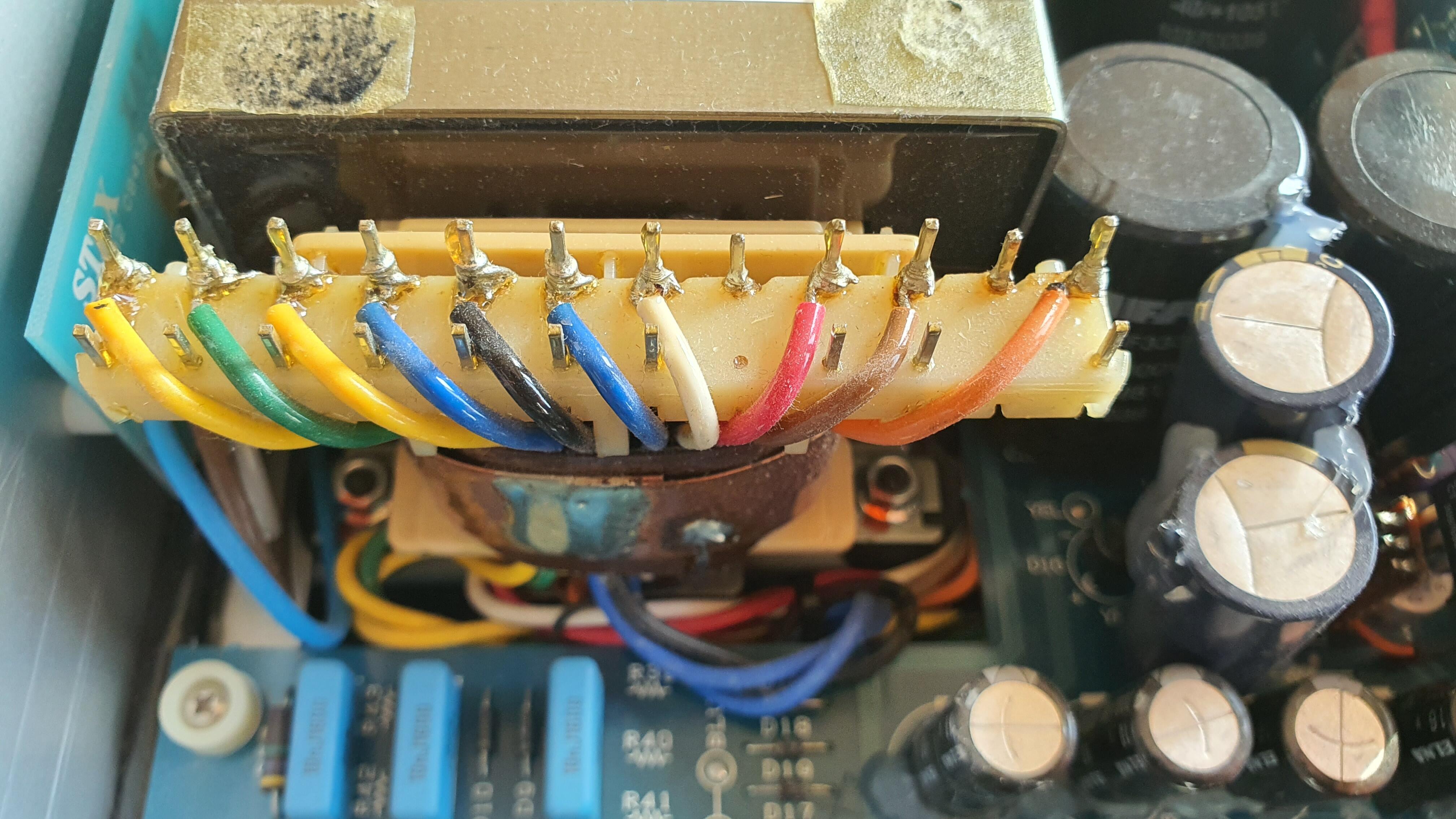
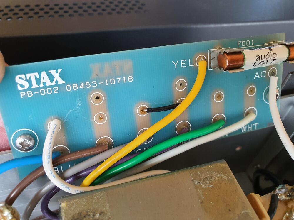
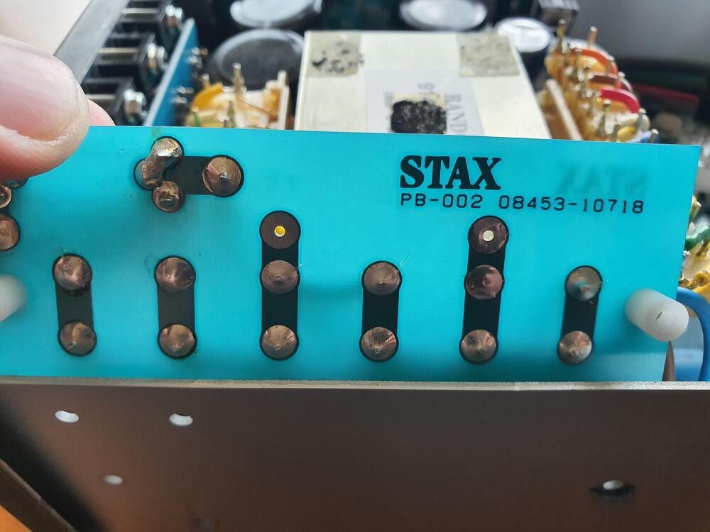
Can I ask for one final confirmation before I proceed with plugging the 007tA in and switching it on? Here are some photos after the modification: Should I do any sort of voltage or impedance measurements, so I can check in advance if everything was done correctly? If yes, what and how exactly to measure? Also, do I have to change the fuse (which in my case is 1,6A)? Haven't touched the bias or anything else. Thanks a lot!

-
-
Thanks a lot for the reply. Can you kindly elaborate a bit about the bias adjustment - if it drifts after the input voltage has been changed from 100V to 240V, will it have to be readjusted? And if it's left untouched, how will that affect the unit's performance? And last thing - do I need to apply any isolation to the the jumpers that I wire to the transformer, or I can leave them soldered only? Thanks again!
-
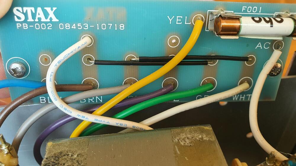
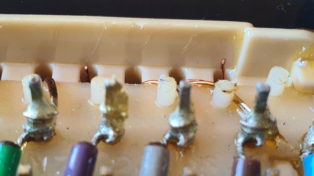
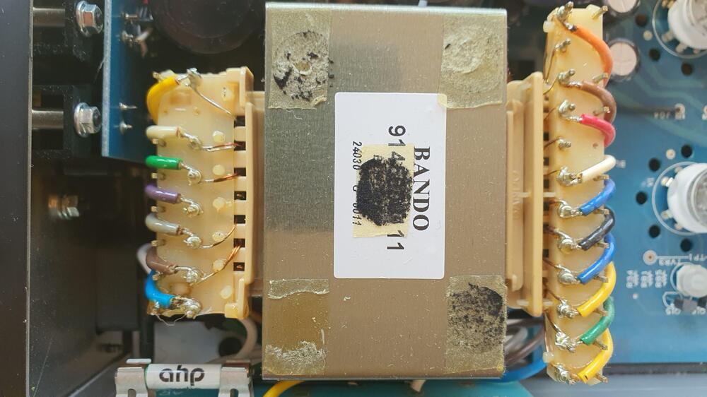
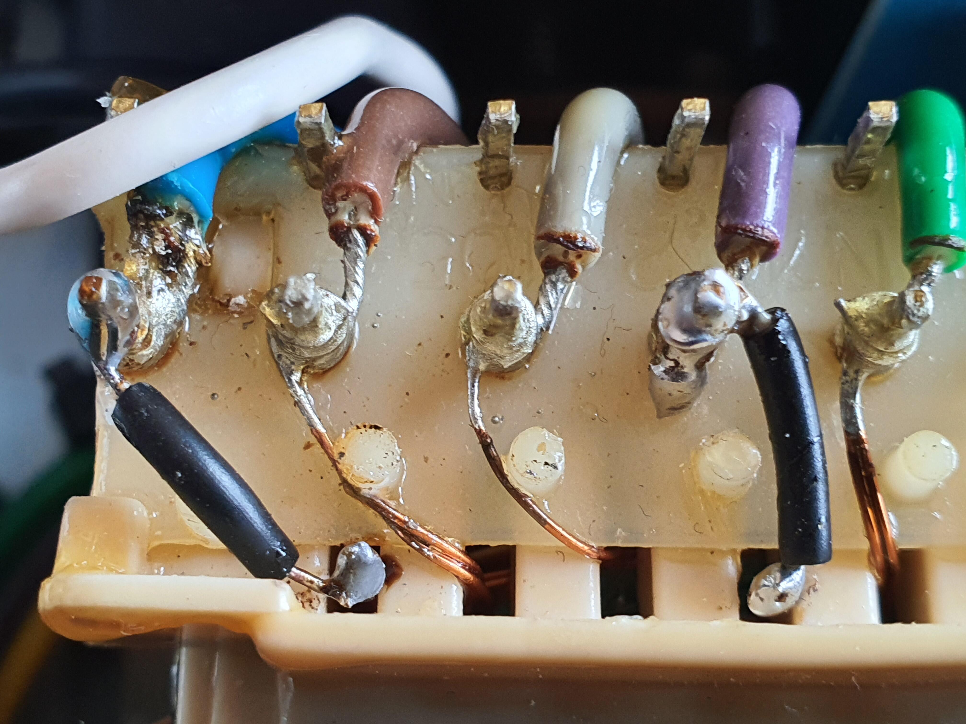
Hello everyone. Found this extremely useful topic, while looking for a way to convert my SRM-007tA from 100V to 240V (220V). While all seems to be explained quite a handful of times, I just wanted to confirm it once more, because I'm pretty scared to not ruin the energizer completely. I do have some questions as well, but first - some photos of the inside of the unit: (not sure if the last photo is relevant at all) It seems like there's just enough copper to solder some jumpers in order to connect the blue and purple wires to the transformer, so I'll do that first. Next is the voltage selection change. Here are the questions: 1. I see couple of options being mentioned here from users, who did exactly what I'm willing to achieve. While both move the white wire from Brown to Blue and removed both black jumpers from their initial position, one of them left the purple wire at its place an put a jumper between Grey and Purple, while the other person moved the purple wire above the grey one (no jumpers used). Does that lead to the same result and which is the better option? 2. Do I need to apply any isolation to the jumpers that I wire to the transformer? 3. I see 220V and 240V being mentioned here - what is the difference and which one is preferred? I think the SRM-007tII is set to 230V, but I don't see that voltage being mentioned here at all. 4. Might be a silly question, but still - the bias on my unit has been adjusted due to tube upgrade. Does that affect the procedure above at all? 5. Another silly question - if all soldering and wiring is done correctly following the guides here, is there still any risk of something going completely wrong? Thanks a lot for your help!