dip16amp
Returning Member
-
Joined
-
Last visited
Everything posted by dip16amp
-
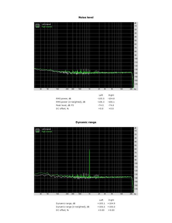
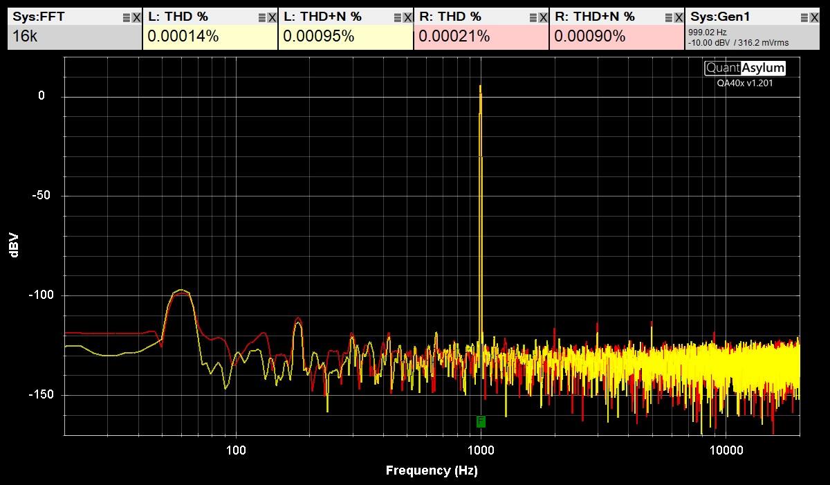
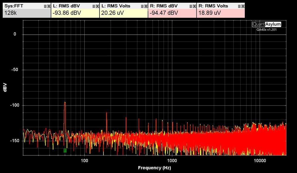
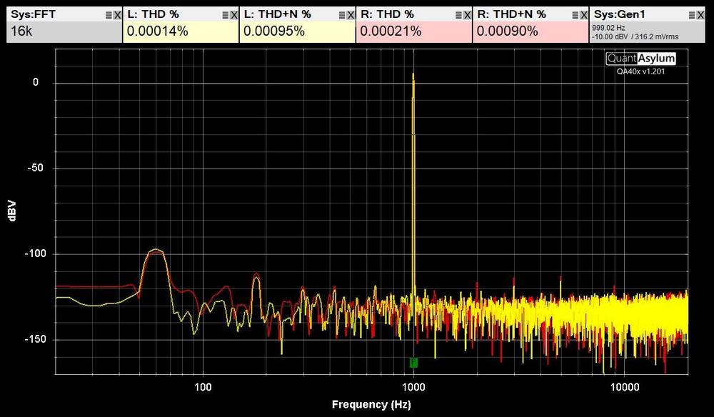
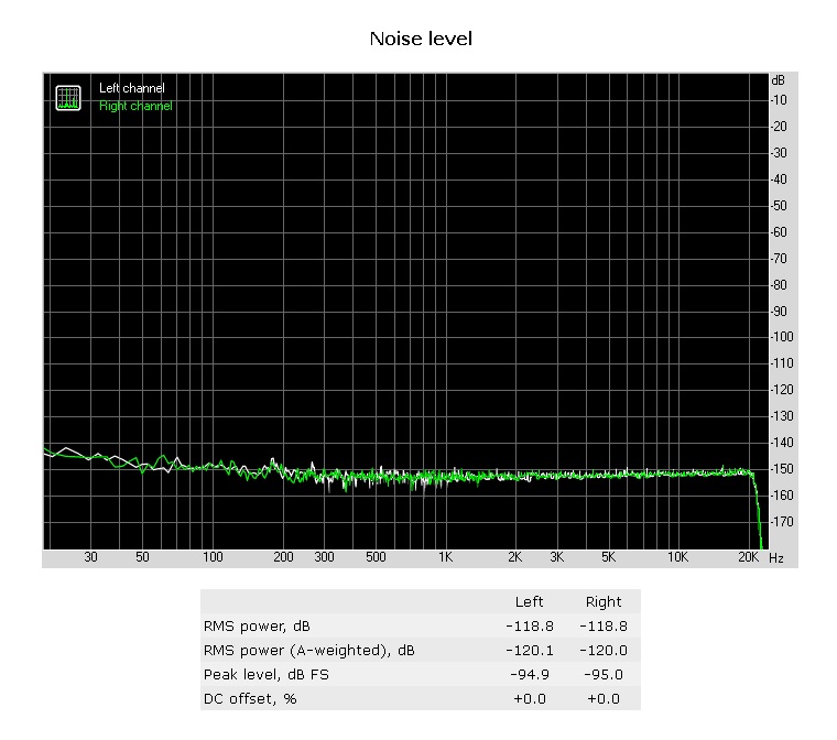
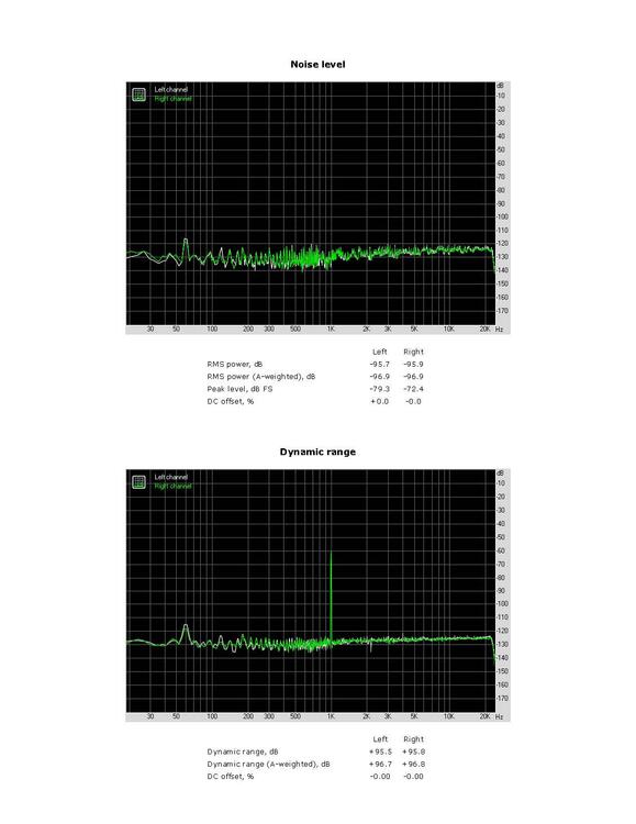
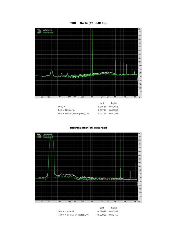
Here is the QA403 software for comparison to RMAA. First image is noise. Second image is THD & THD+N.
-
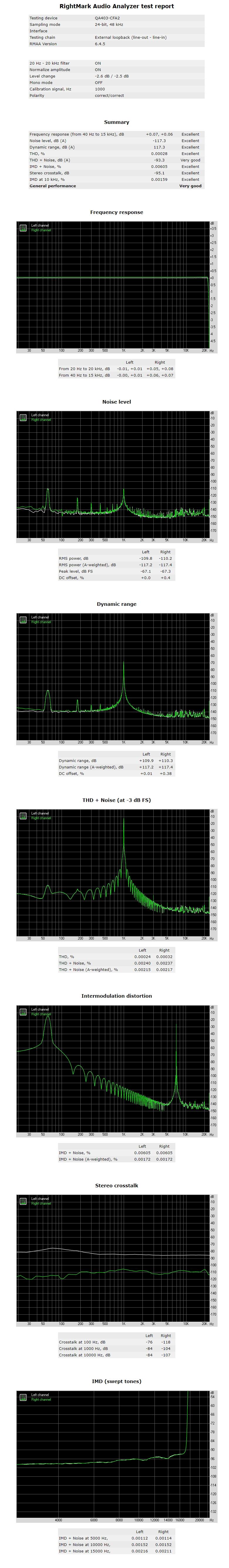
Here is the QA403 with BNC to XLR cables run on my balanced CFA2 amplifier with RMAA. The ASIO401 driver is configured for -12.0 output to adjust for the 10 dB gain of the amplifier.
-
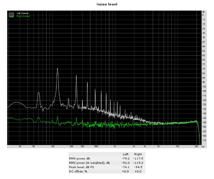
Here is the A-Weighted measurement.
-
I put a solen mkp 1uf between the QA403 input and GRLV output and got more noise.
-
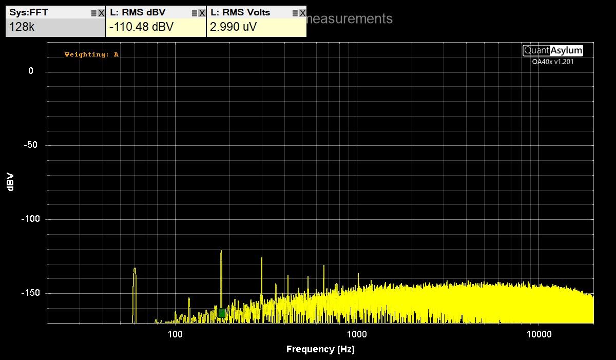
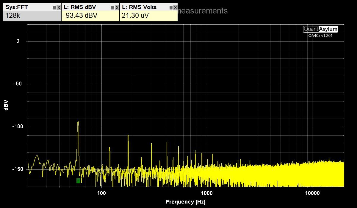
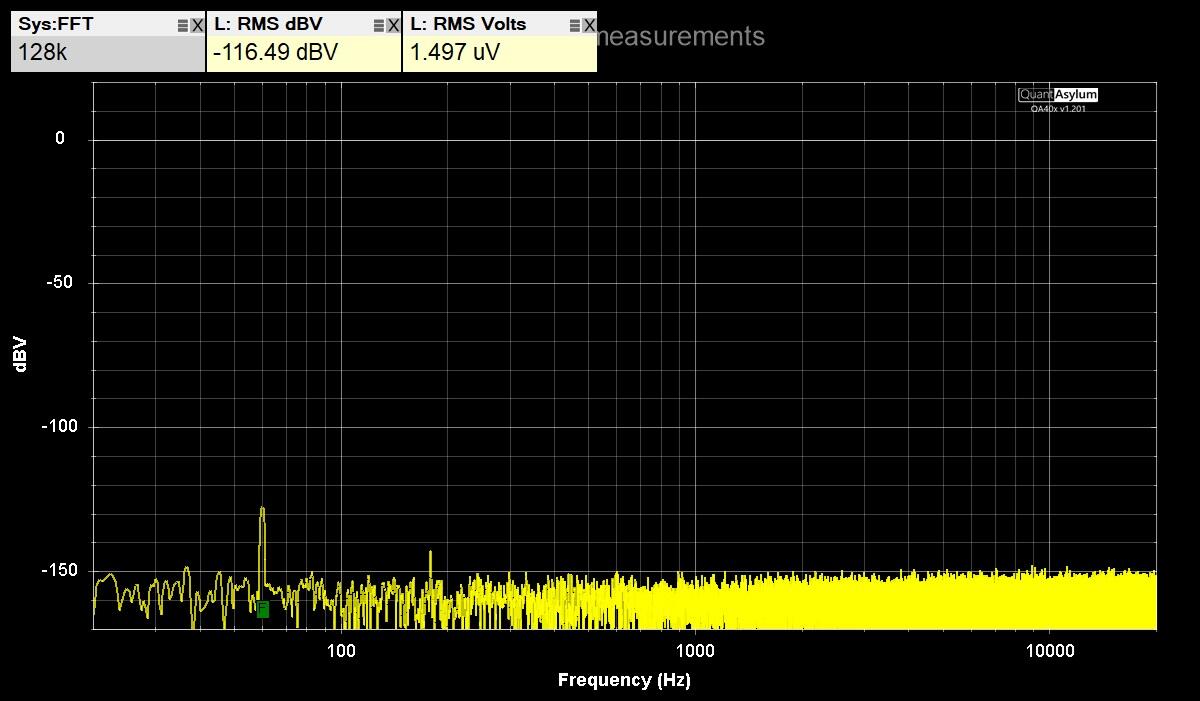
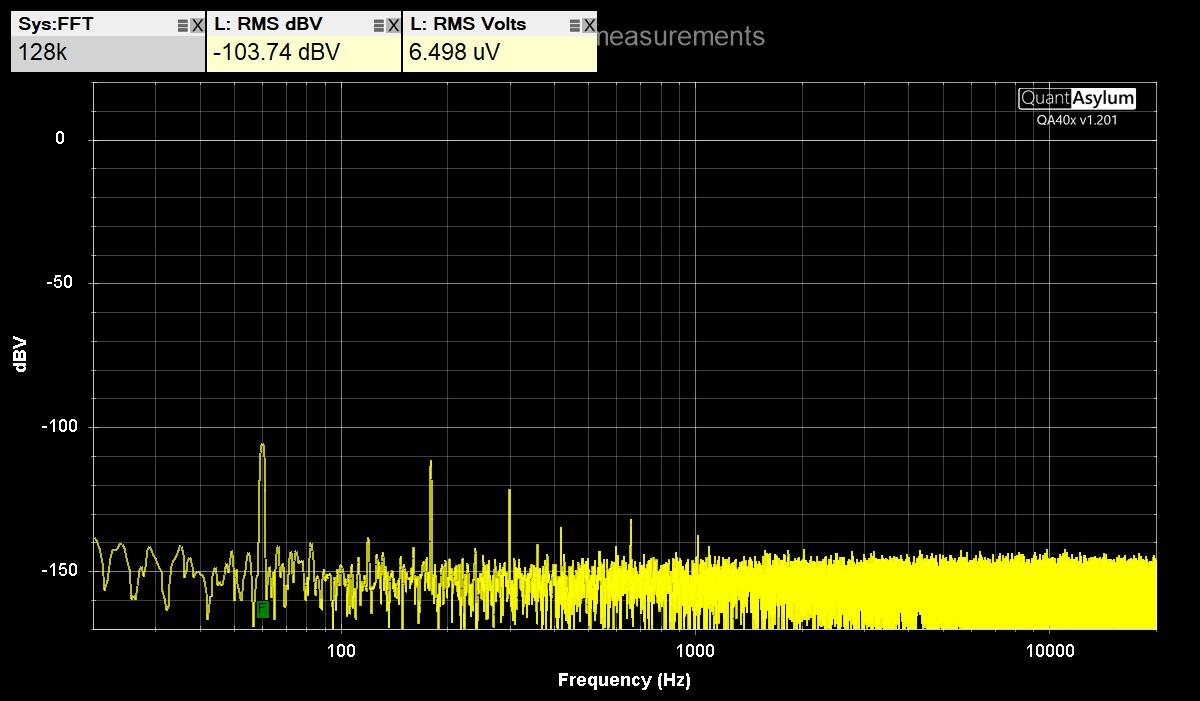
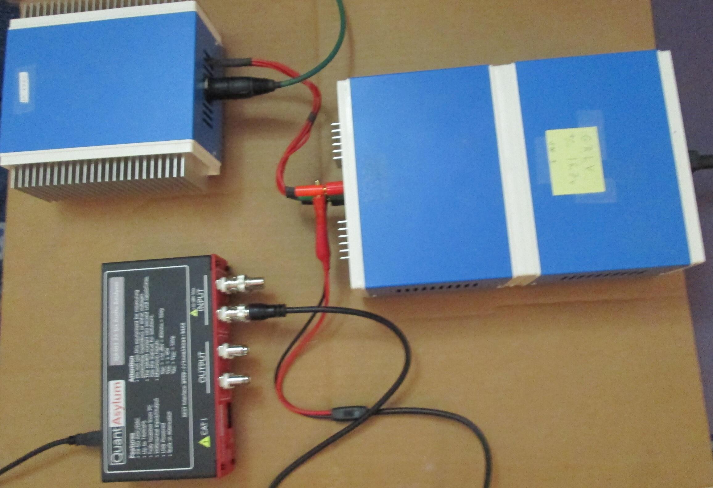
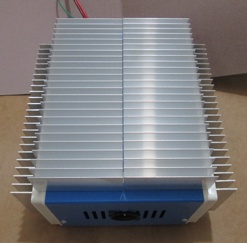
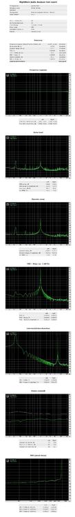
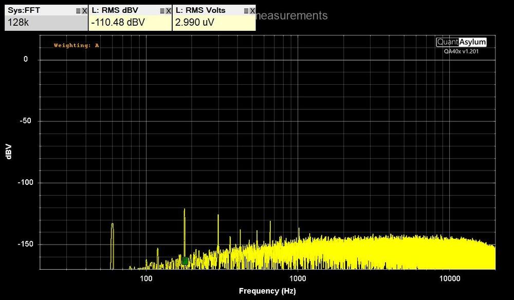
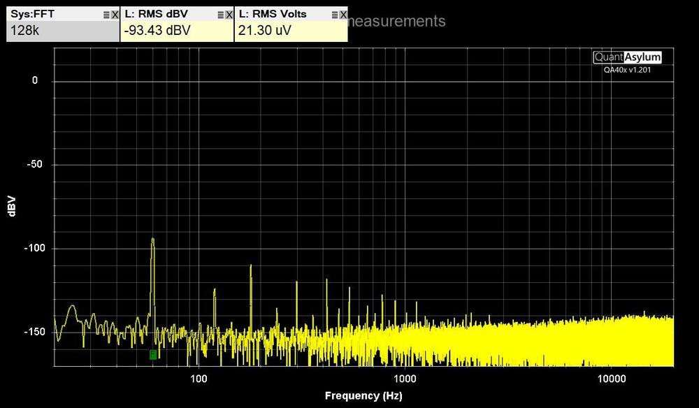
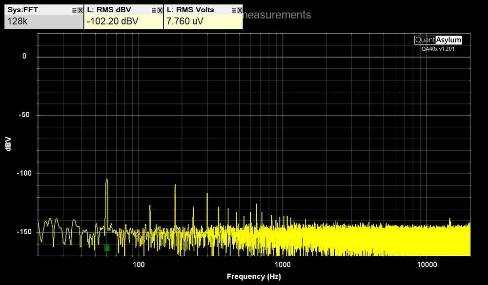
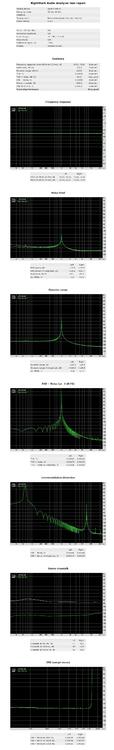
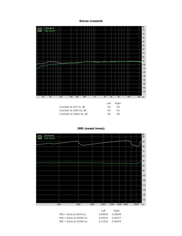
QuantAsylum QA403 tests Tested my GRLV noise level with the QA403 by connecting it directly with BNC test leads. The maximum DC input of the QA403 is 40 VDC. Measured the positive and negative voltages separately to see each noise level. Used the left positive input BNC and put a terminator on the negative input BNC. Installed software from https://github.com/QuantAsylum/QA40x/releases/download/1.201/setup_QA40x_1.201.exe Start app and Select File-> Devices-> QA403 Select File-> New Settings, Set the FFT size to 128k, the full scale input to 0 dBV, and hit Run. The first image is with the 36" BNC test leads alligator clips shorted together. The second image is the QA403 connected to the GRLV with no load. The third image is the GRLV with CFA2 as the load. Have less than 8 uV RMS Volts on each output. Was able to run RMAA on the QA403 by installing ASIO drivers. https://github.com/dechamps/ASIO401 Install https://github.com/dechamps/ASIO401/releases/download/asio401-2.0/ASIO401-2.0.exe Have to adjust the input/output scaling with the configuration file ASIO401.toml in the Windows user profile folder; for example: C:\Users\Your Name\ASIO401.toml Make sure the file doesn't have .txt on the end of it. My settings for the RMAA loopback cable tests are: fullScaleInputLevelDBV = +6.0 fullScaleOutputLevelDBV = -2.0 Adjust levels when testing an amplifier with gain. The input values can be: 0.0, +6.0, +12.0, +18.0, +24.0, +30.0, +36.0 and +42.0 The output values can be: -12.0, -2.0, +8.0 and +18.0 Install RMAA https://audio.rightmark.org/downloads/rmaa6.exe Right click and Run as administrator. Start it and select ASIO401 for input and output device. Select 24 bit and 48 kHz. Install four coax bnc loopback cables from output to input on the QA403. select Playback/Recording icon. start test if signal levels are good, otherwise adjust levels in ASIO configuration file. when test is done, save to location. Generate a RMAA test report with the paperclip icon. The test report has misspelled configuration signal as singal. I used hexinator app to edit the rmaa6 executable C:\Program Files (x86)\Rightmark\rmaa6 Select Edit, Find, singal at 496C00 Change the hex code 6E 67 to 67 6E and save. Here are the results of the RMAA balanced loopback tests in the last image. A picture of the QA493, GRLV, CFA2 is the fourth picture. The GRLV has the transformers in the rear box and the regulators in the front box. Two steel panels separate them to lower noise.


-
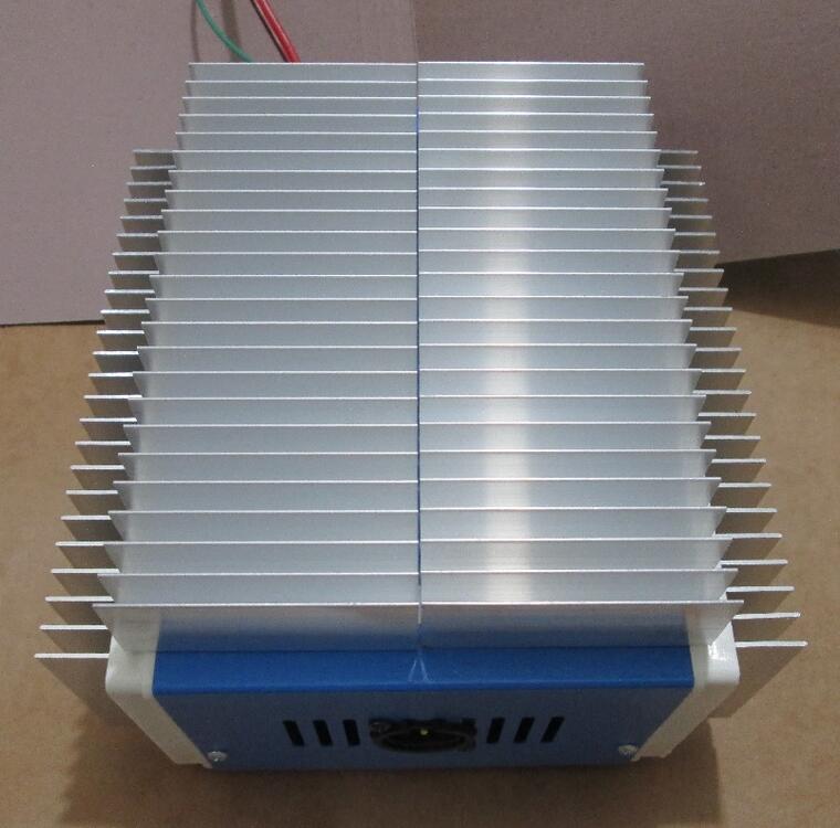
that was with my +/- 16.7v grlv i ran it again for an hour on my +/- 28.8v grlv at 150ma min temp 0 32 5 49 10 56 15 59 20 61 25 60 30 60 35 60 40 62 45 63 50 63 55 63 60 62 it could probably run to 100c but should not get higher than 70c
-
ran my CFA2LT for 70 minutes at 140ma and it got up to 49c used a fluke 87v with thermocouple probe on the middle 2sa1860 mounting screw minute temp 0 23 5 34 10 39 15 42 20 44 25 46 30 47 45 48 48 49 60 48 70 48
-
I noticed that 1 of the 3 bias was lower than the other 2 after warming up. Had to add a couple of 20 gauge copper strips to thermally connect the 2 heat sinks together.
-
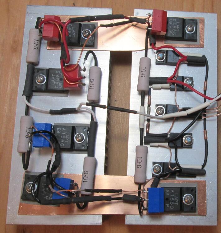
Here is my new CFA2 LargeT version up and running with large triple output transistors pairs it first started up at 200ma bias and turned it down to 150ma offset is less than 1mv with the servo The big resistors are 1 ohm 5 watt 2% Metal Oxide Film MOSX5C1R0G the other resistors are RN55 & CMF55 the caps are 560pf 100v FG28C0G2A561JNT0 47uf 25v FG26X5R1E476MRT0
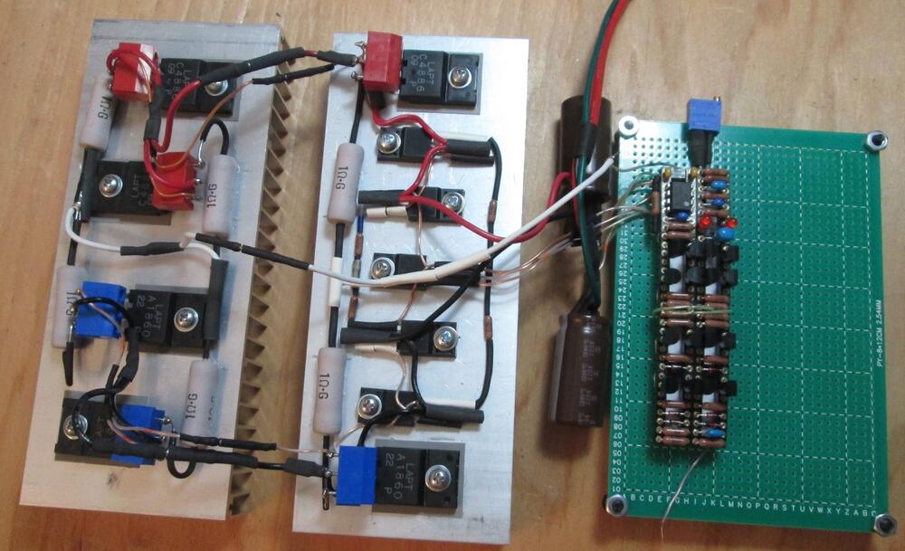
-
Good to hear the problem is solved. Sometimes stuff happens, but at least it can be corrected.
-
I'd measure the voltage across each 1 ohm resistors, then the 1m, 100, and 560 ohm resisters.
-
What is the offset without the op amp? It should be around 40mV. Then the op amp will bring it down to near zero. Don't think the transistors hfe would be the cause of high offset. What are the other boards offset without the op amps?
-
If the 5k pot measures the same as the good board but it's position is at it's end, maybe replace the pot.
-
Just replace both 1 ohm resistors and the one bad 15030. Everything else should be fine. Measure resistance across the 15031 and 15030 to find a shorted one. I've only had a bad 15031. Measure resistance across both resistors may be 1.5 ohms instead of 2 ohms. Measure these in circuit with power off.
-
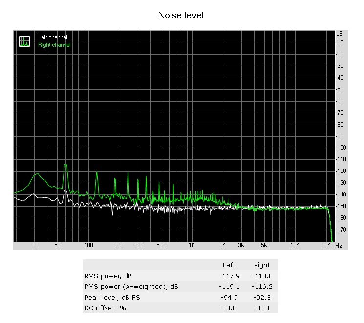
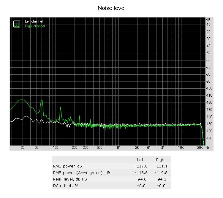
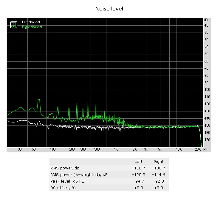
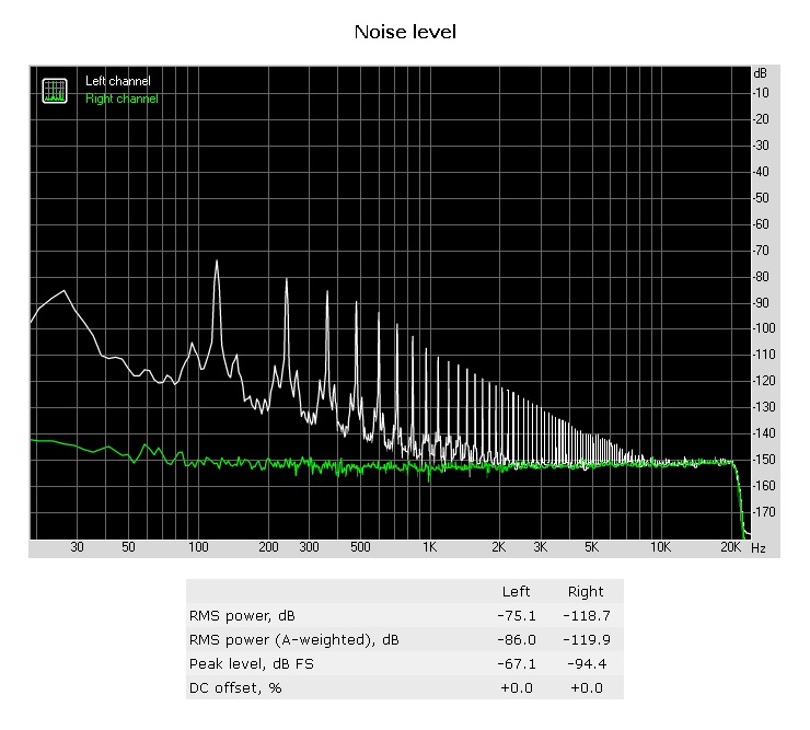
i forgot to set the drok input voltage setting to 115 vice 230. thought i was in the habit of checking that first before using. now i can get 35 volts at 8 amps before reaching my load tester limit. put a 3k resistor in my grlv to get 30 volts out. now i get 30 volts at 8 amps out on a load test. here is the noise level before and after the grlv regulator during the 8 amp load test.
-
found a couple 121 ohm resistors and here is what i get now amps volts 1a 23.35v 2a 23.36v 3a 23.37v 4a 23.38v 5a 23.39v 6a 23.40v 7a 23.40v 8a 23.40v 9a 23.41v 10a 23.41v
-
ok, let me find some 120 ohm resistors.
-
but the mjw21196 is rated for 16 amps what could go wrong? do you need to redesign the grlv for 10 amps? do i have to modify something or is it good as is? i know the load tester is only rated for 200w and it survived i can get a 60v 8a adjustable power supply for $47. maybe it can do 35v at 8a only 8 amps tho
-
i load tested the drok 48v 10a power supply and only got up to 27v at 10a with a rigol dl3021a dc electronic load tester here is the 1a steps (edit: forgot to set the drok input voltage setting to 115 vice 230) i was able to get 35 volts at 8 amps before reaching my load tester limit. anps volts 1a 36v 2a 35v 3a 34v 4a 33v 5a 32.6v 6a 32v 7a 31v 8a 30v 9a 28v 10a 27v then i connected a grlv with a 2k resistor to output 23.3v and load tested it amps volts 1a 23.3v 2a 23.2v 3a 23.2v 4a 23.1v 5a 23.1v 6a 23.0v 7a 23.0v 8a 22.9v 9a 22.9v 10a 22.8v
-
I used the bk1735 to replace the transformer as input to the grlv circuit. here is the noise level before and after the grlv then i tested an adjustable 0-48v 10a power supply i found on amazon for $40 DROK 48V Power Supply, AC 110V/220V to DC 0-48V 10A and tested it before and after the grlv
-
you're right in i have not calibrated it to 1v so i can't say 1uv, I'll strike that. from the post. this does let me see noise on power supplies for comparison like this bk1735.
-
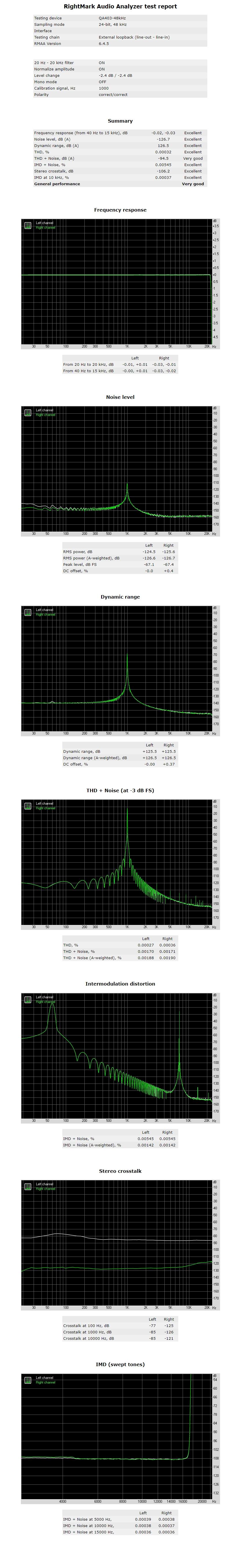
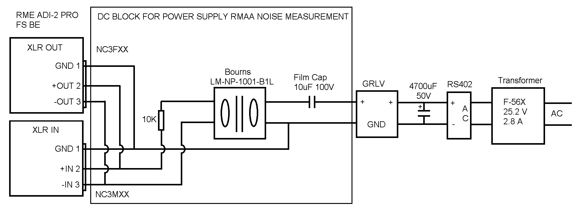
I've been able to use my RME ADI-2 PRO & RMAA 6.4.5 to measure GRLV power supply output noise. Kevin asked about using my setup with a DC block. It started with a 10uf film cap and 10k resistor then an audio transformer to isolate the RME from the power supply. I discovered a few sources of noise and removed them to get the GRLV output noise down to -120 dB. The first source of noise was 50 Hz and it's harmonics from 7 LED volt meter displays. The second was from not having ground connected from the RME to the power supply. The third was 60 Hz and it's harmonics because the GRLV circuit was too close to the power transformers. 1" was too close and 4" was much better. The pics in the previous post shows the progress over the last 10 days. The final 2 pics show the positive and negative voltage outputs on left and right channels. Then the final pic shows before and after the GRLV circuit. Here is the DC block circuit used to measure the output noise. I used one for each channel.

-
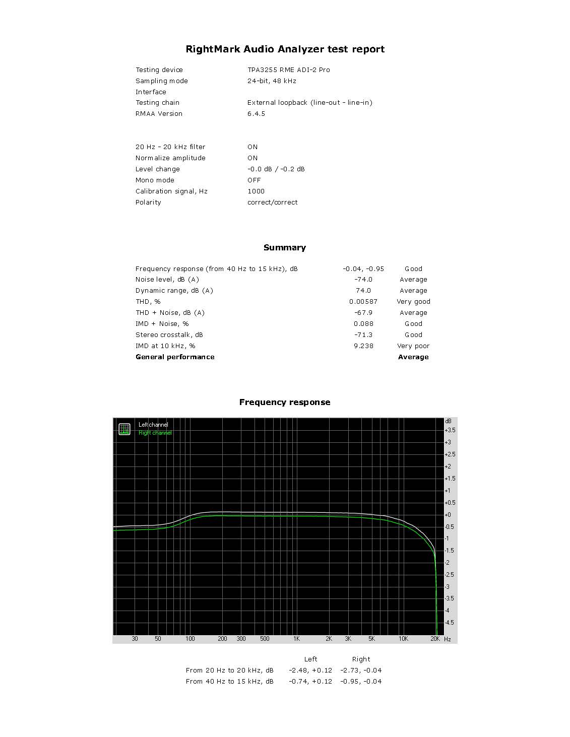
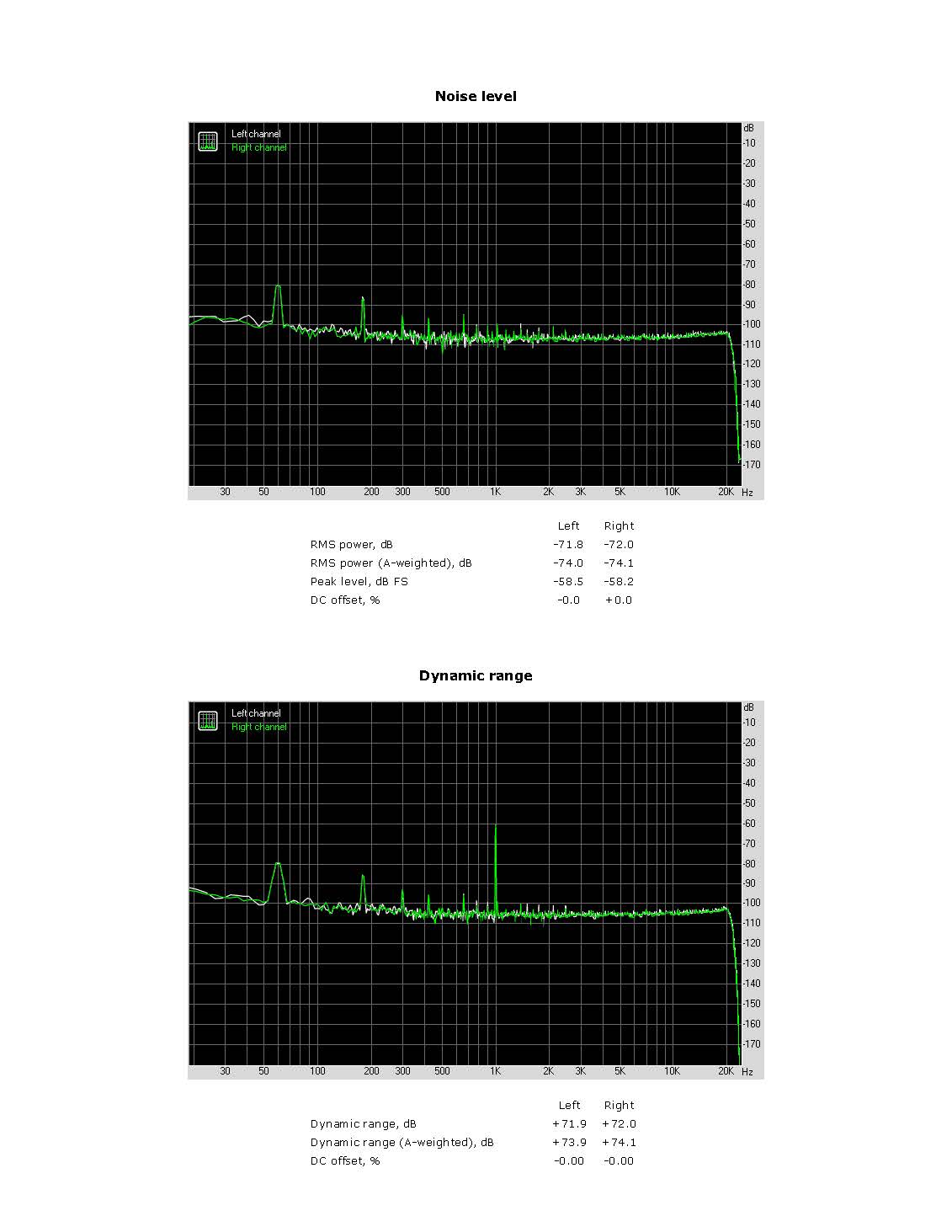
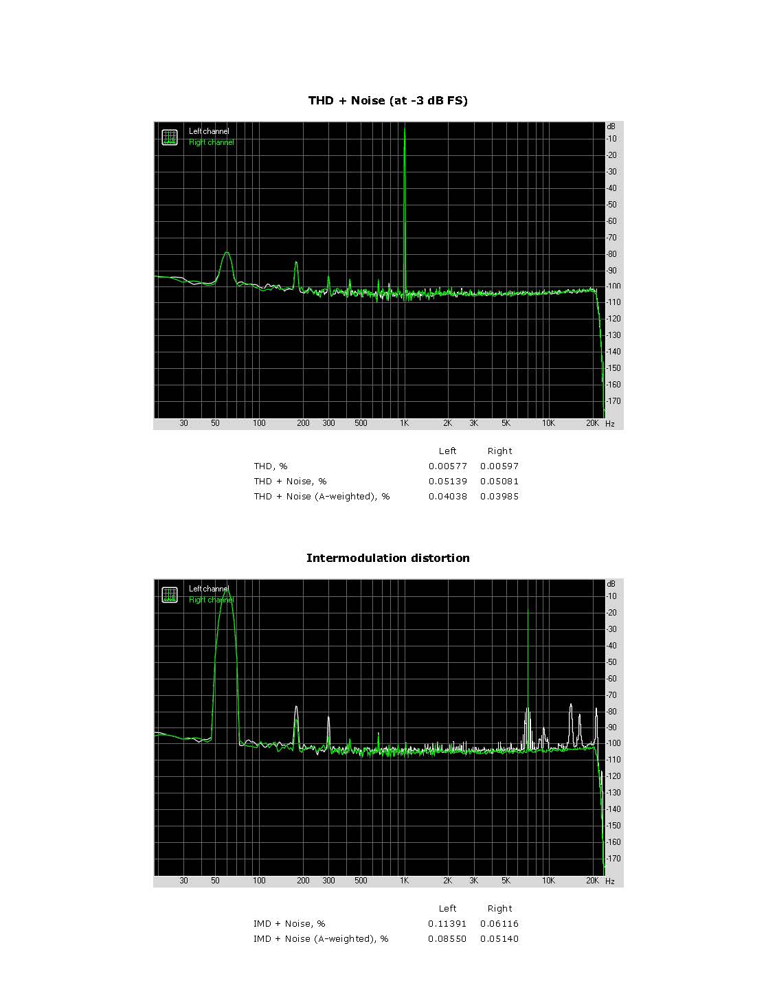
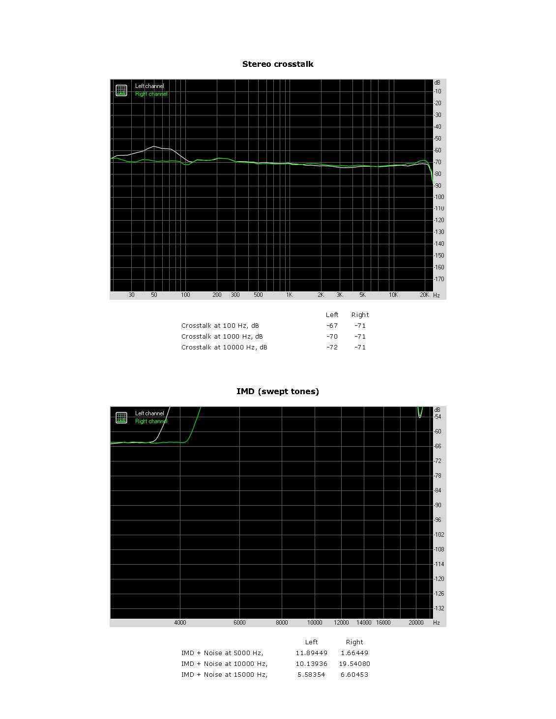
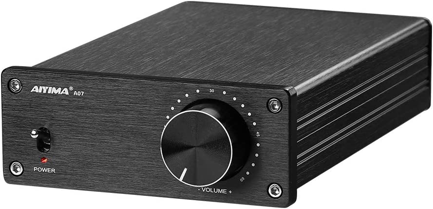
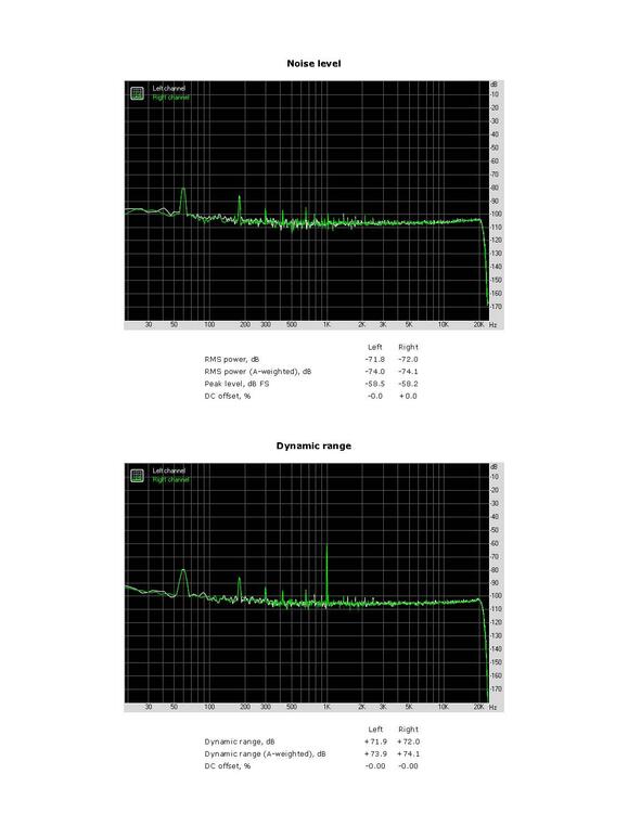
Found this TPA3255 on Amazon for $65 AIYIMA A07 TPA3255 Power Amplifier 300Wx2 RightMark Audio Analyzer test _ TPA3255 RME ADI-2 Pro.pdf

-
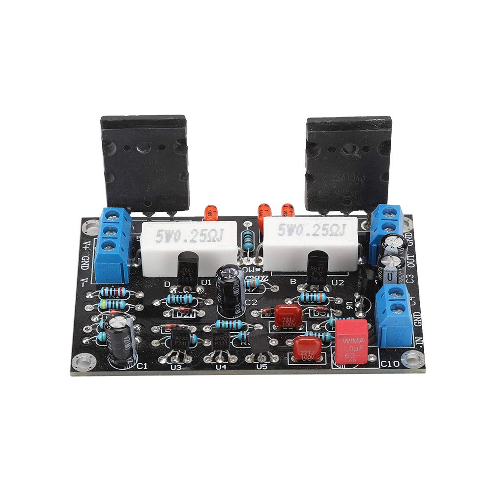
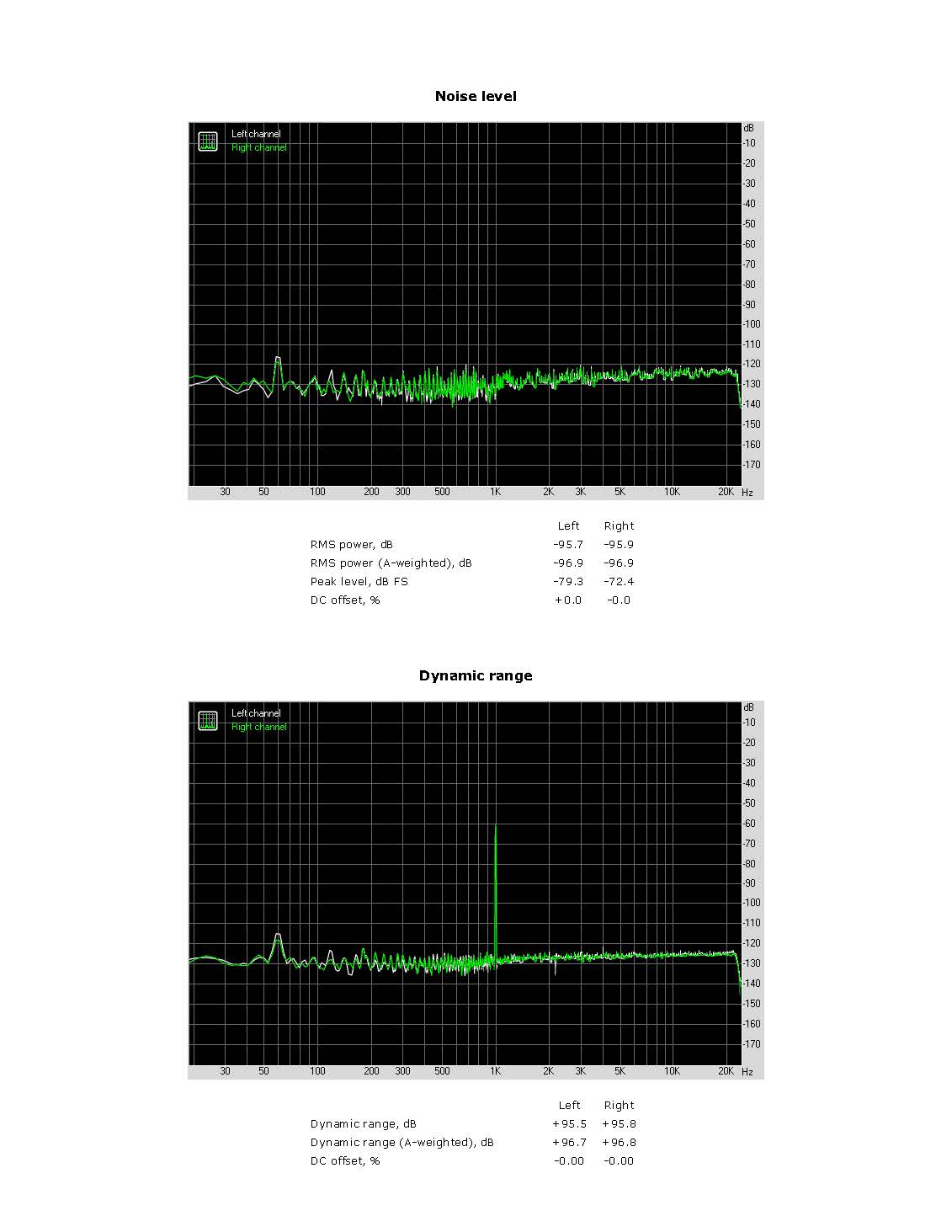
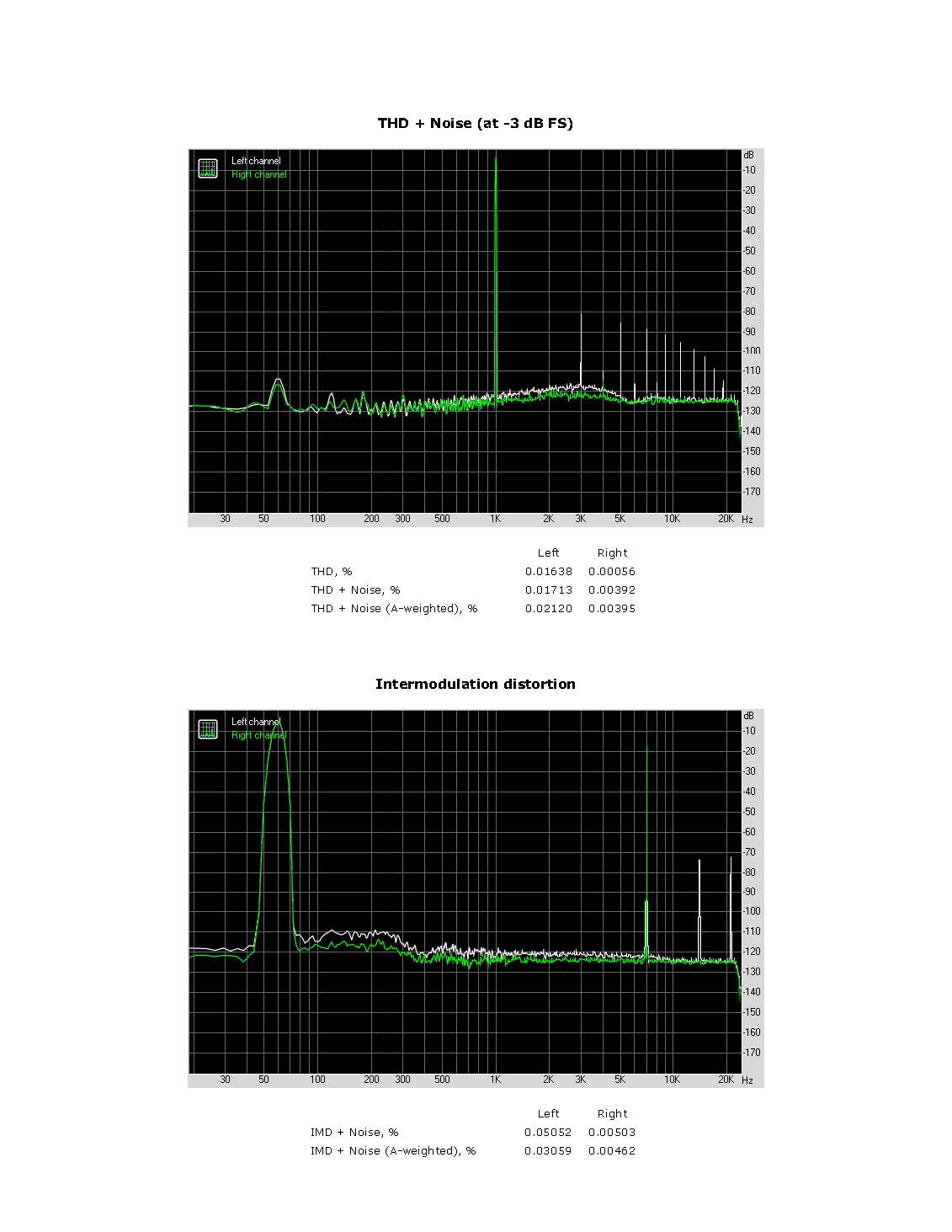
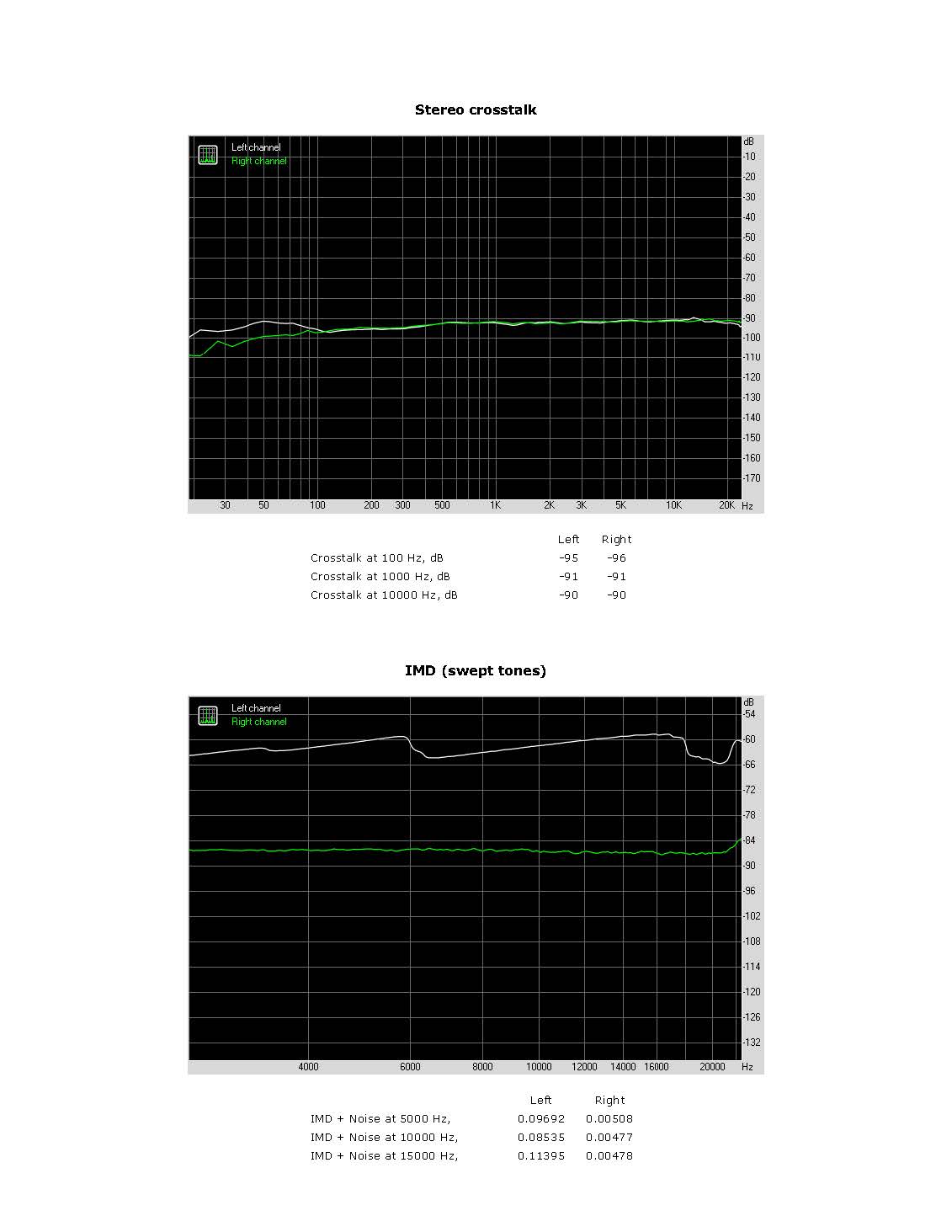
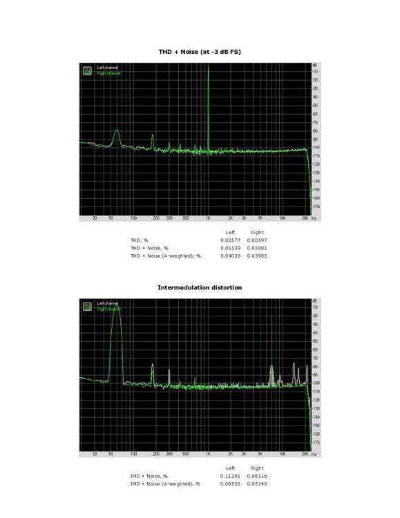
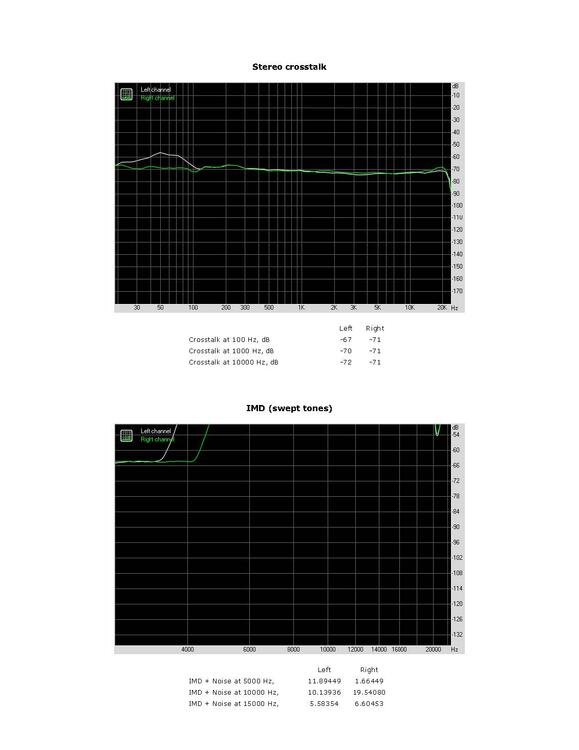
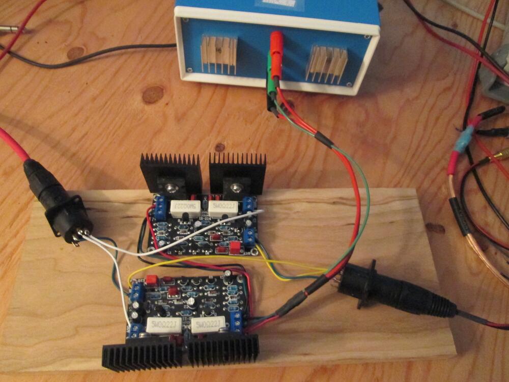
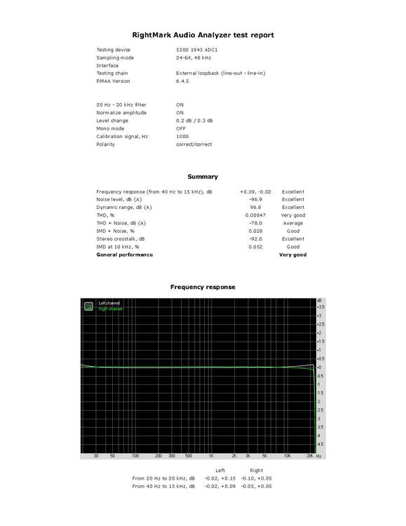
Also found this 5200/1943 board on Amazon for $16. Vbestlife 2SC5200+2SA1943 Power Amplifier Board 100W Set it up as balanced mono on the left channel and compared it to a XLR cable on the right channel. It has about 23 dB gain. RightMark Audio Analyzer test _ 5200 1943 ADC1.pdf

-
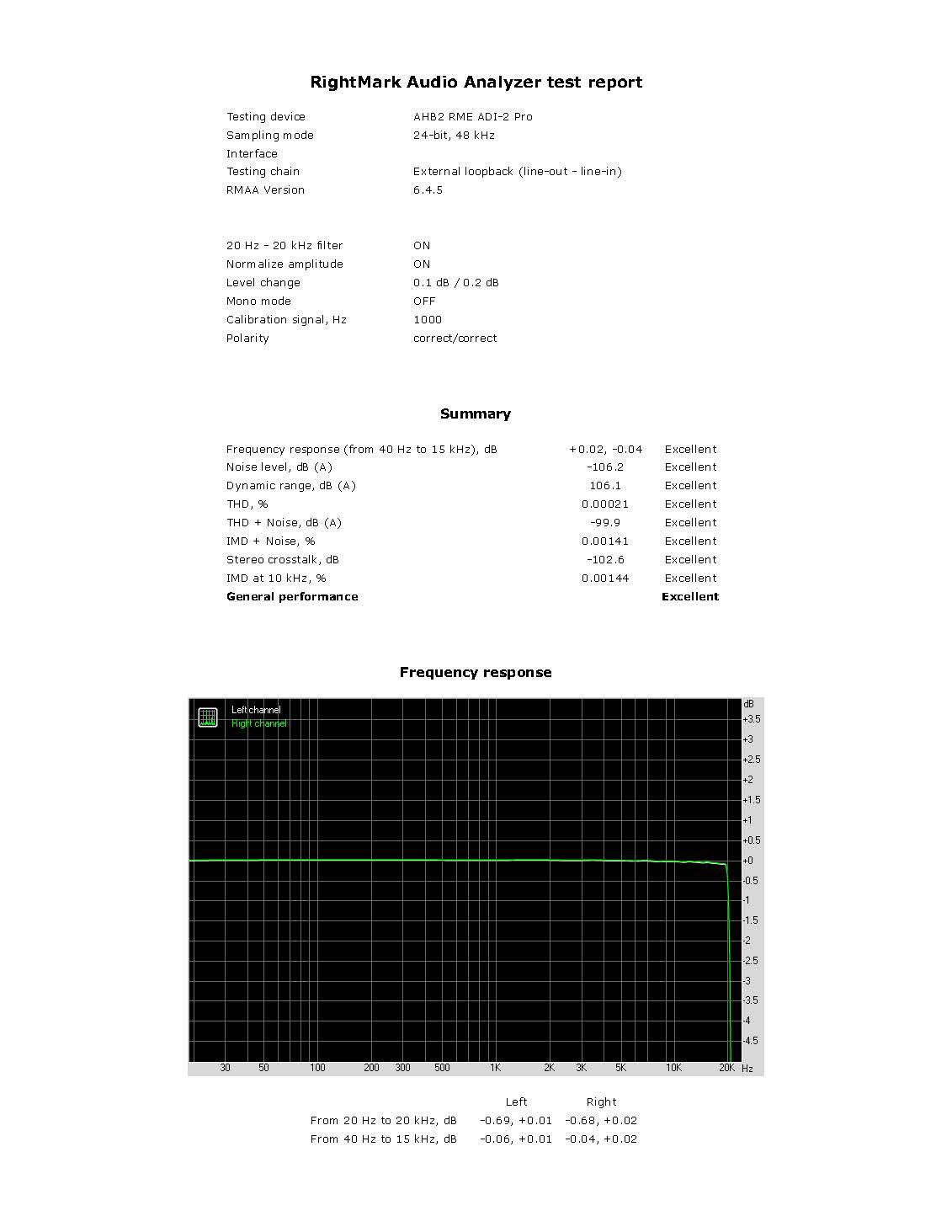
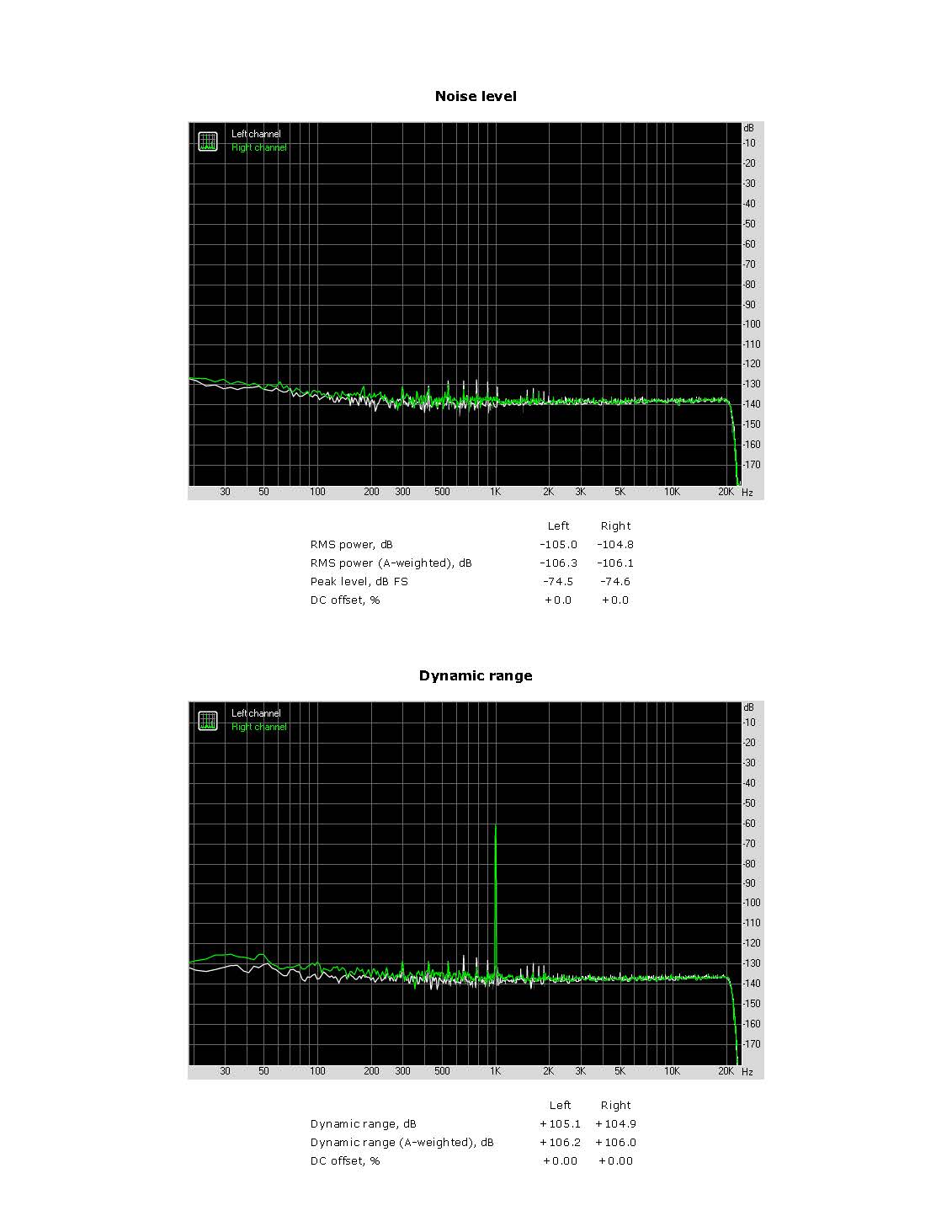
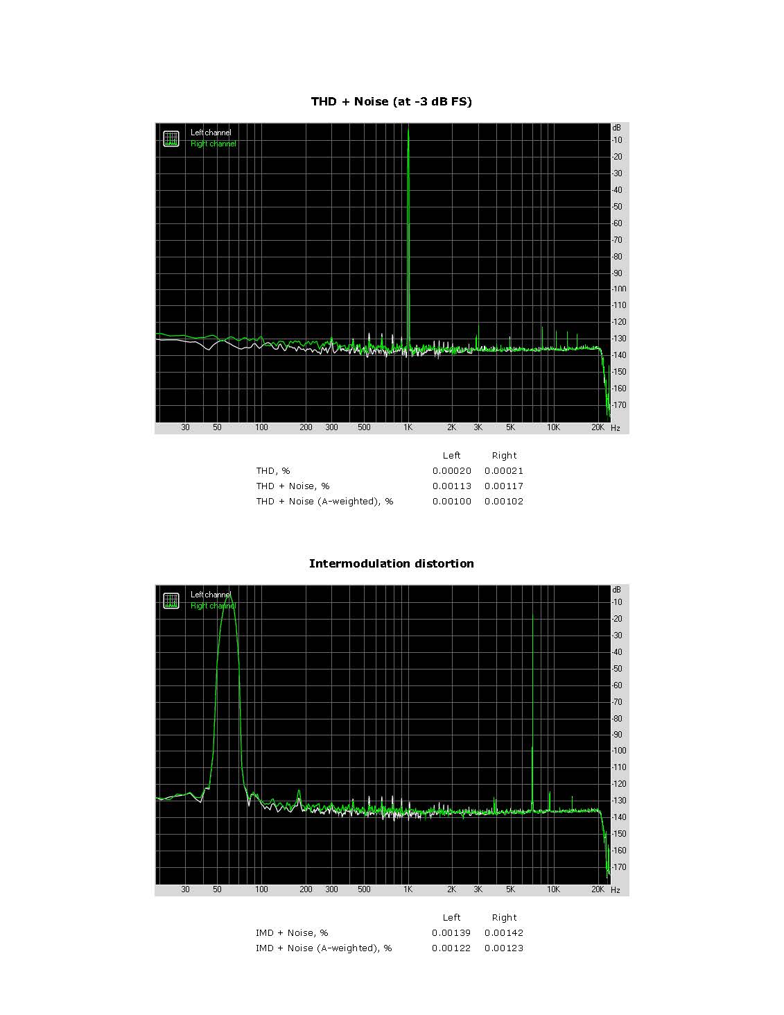
Here is the Benchmark AHB2 RMAA on the RME. RightMark Audio Analyzer test _ AHB2 RME ADI-2 Pro.pdf