dip16amp
Returning Member
-
Joined
-
Last visited
Everything posted by dip16amp
-
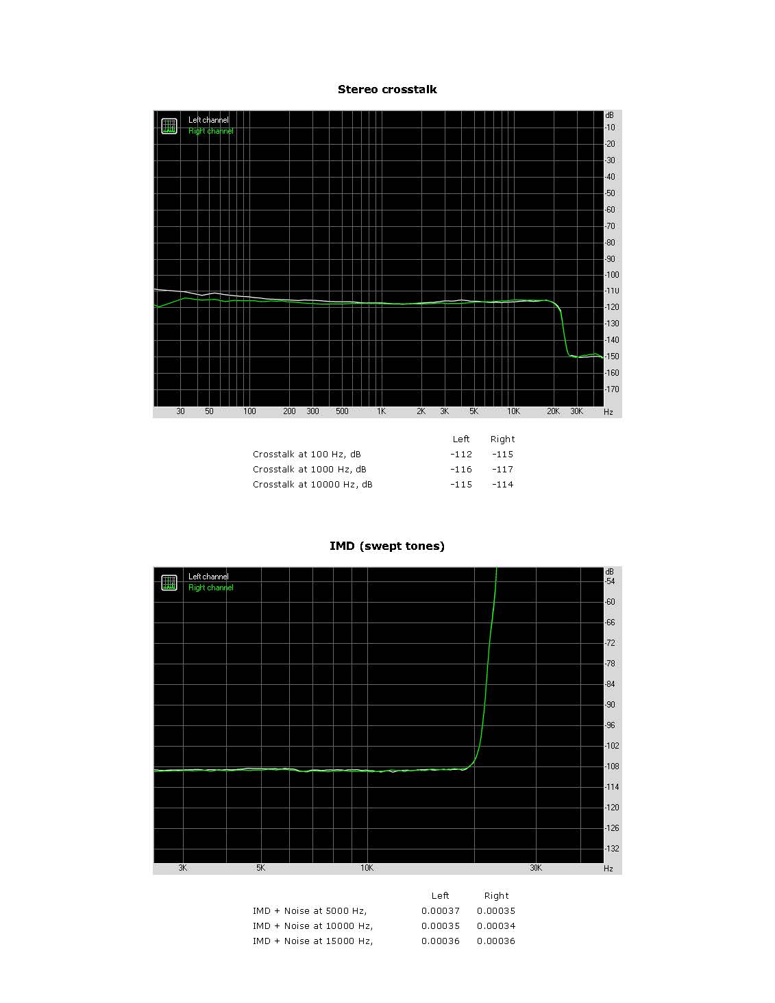
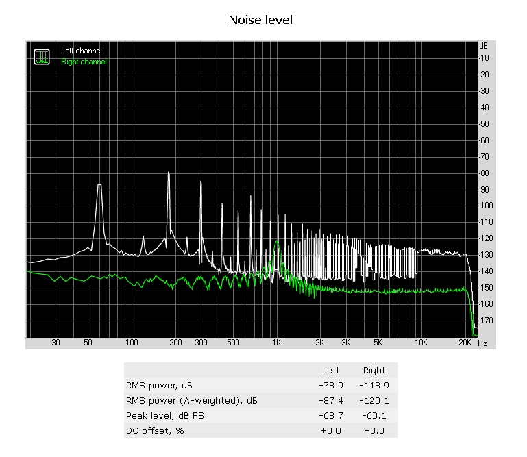
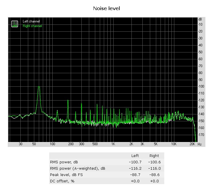
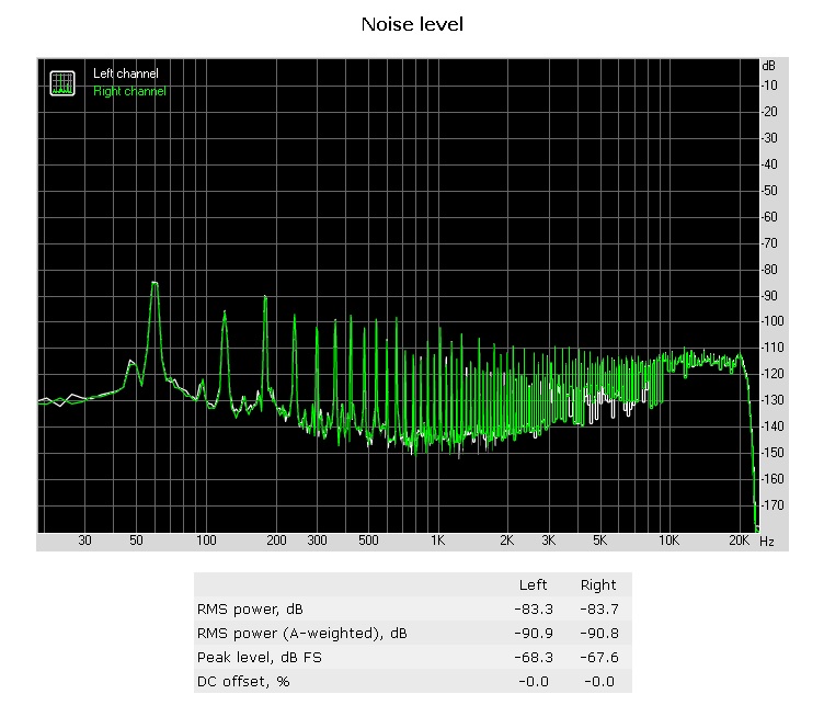
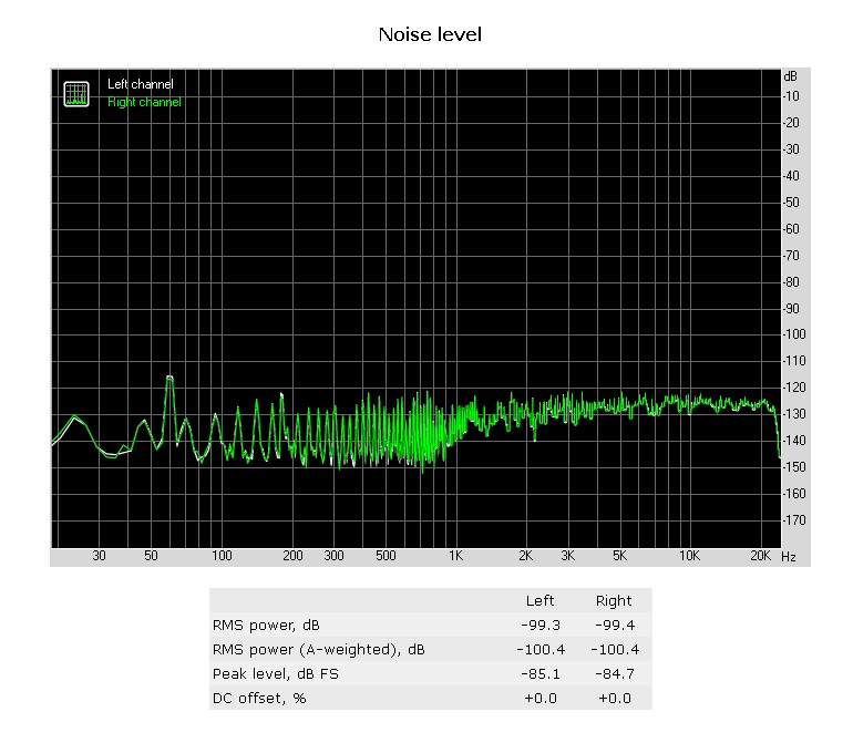
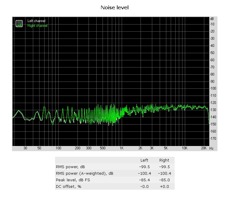
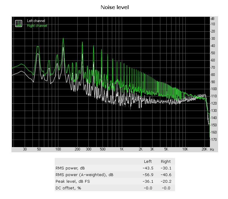
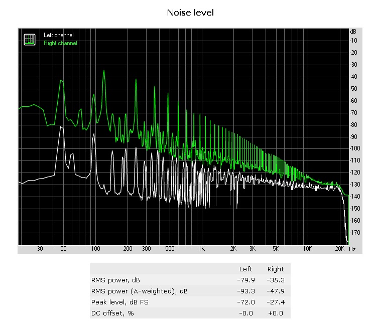
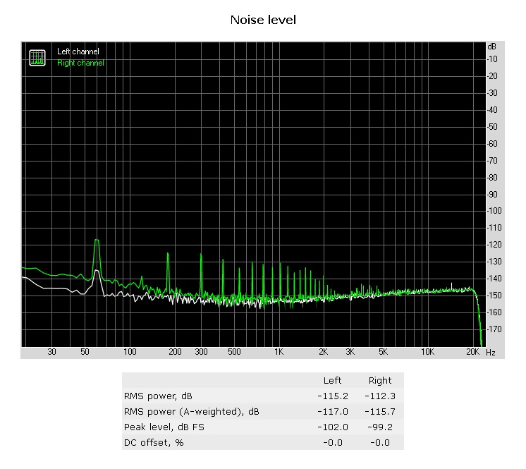
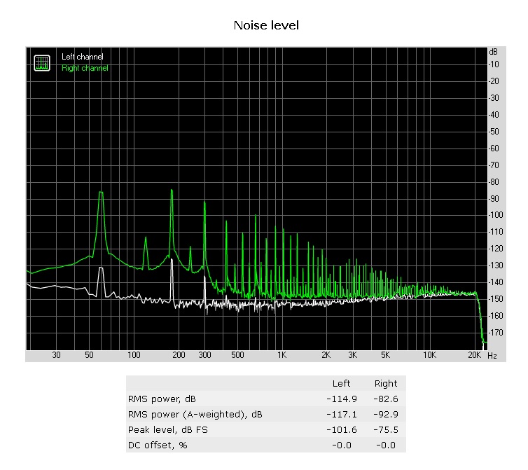
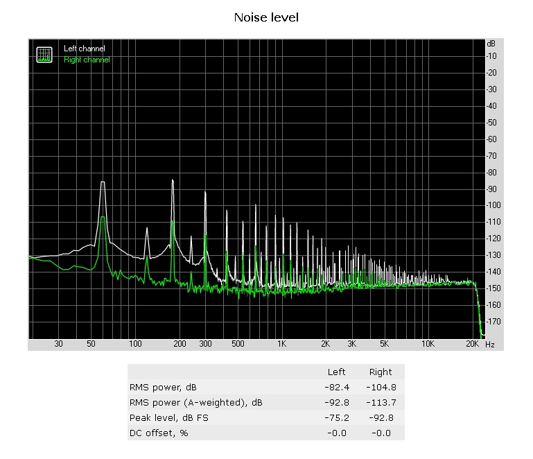
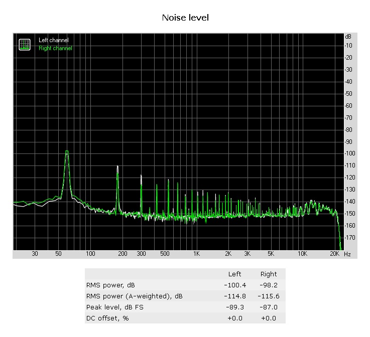
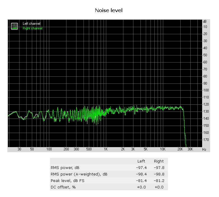
GRLV noise frequency graph.


-
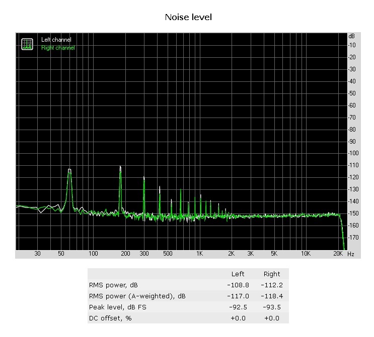
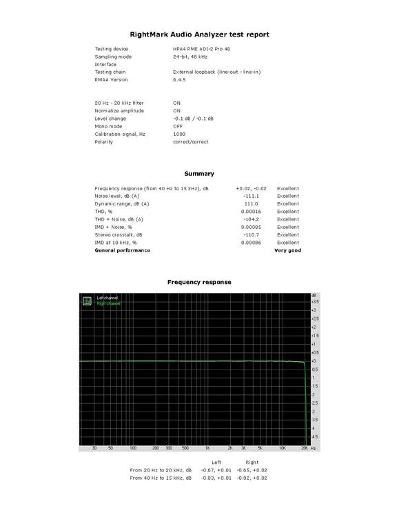
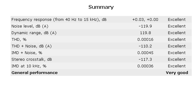
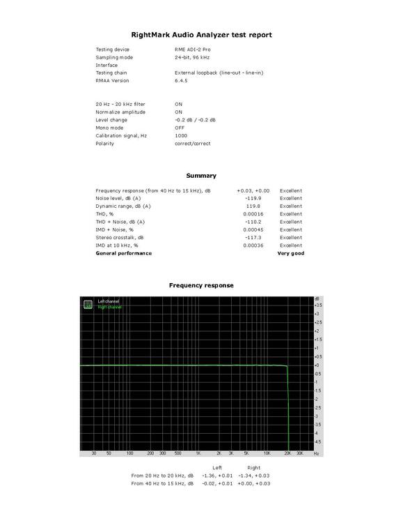
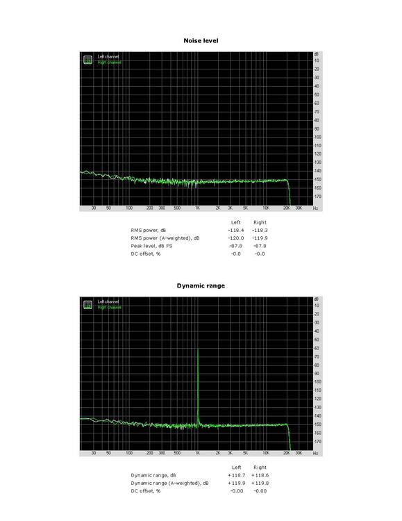
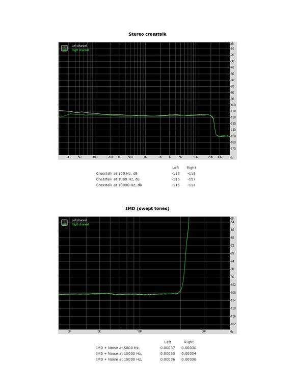
Here is the HPA4 & RME RMAA. RightMark Audio Analyzer test _ HPA4 RME ADI-2 Pro 48.pdf

-
I should test my Benchmark HPA4 or AHB2 on the RME.
-
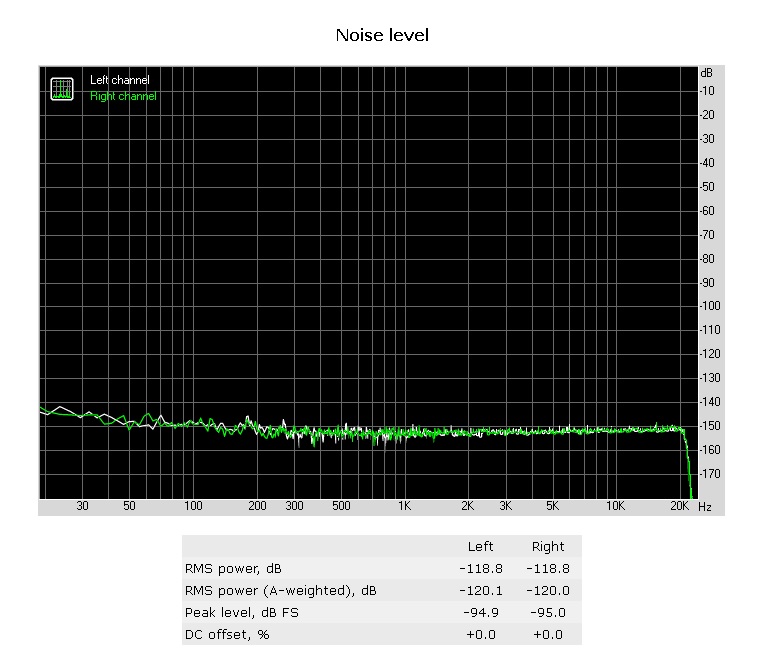
That was without the steel covers. When I put the covers on, it looks like this:

-
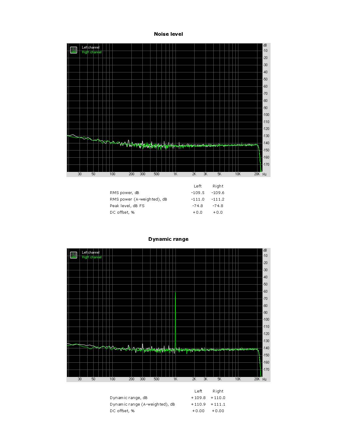
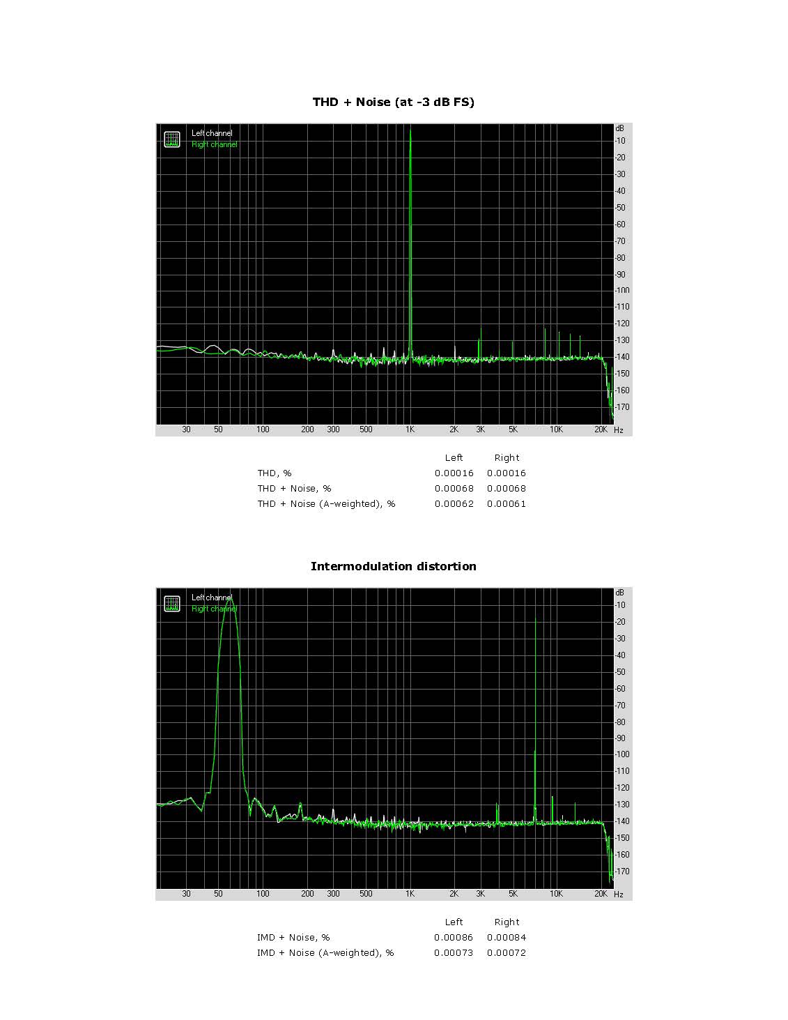
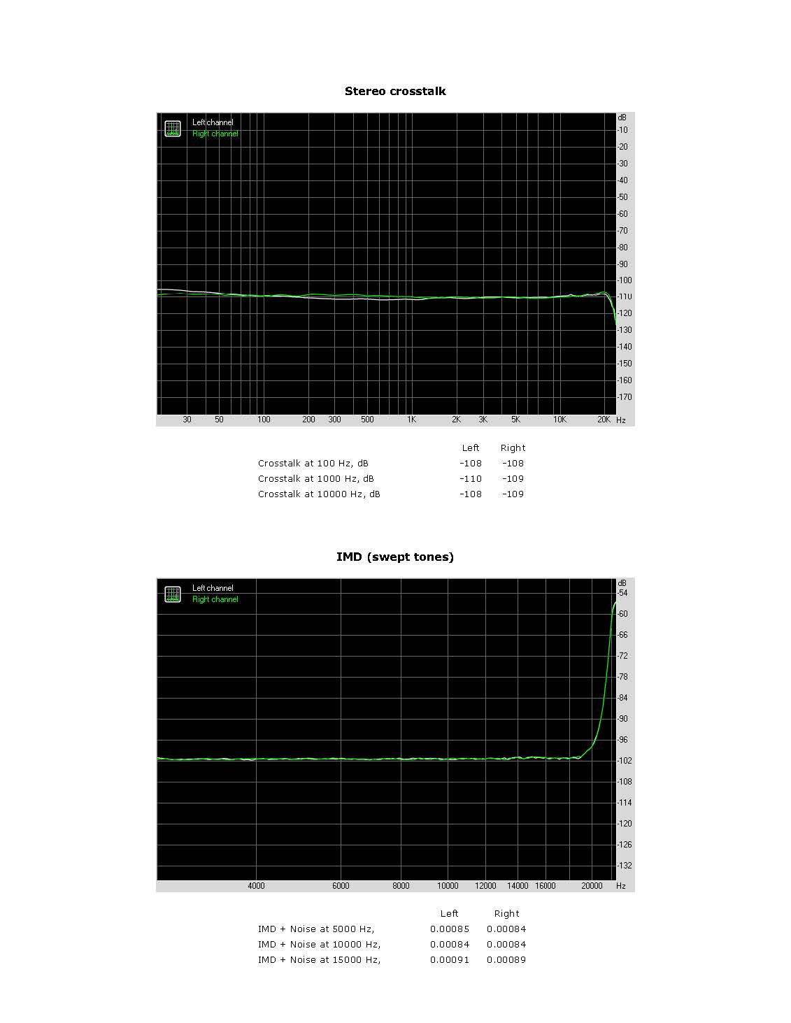
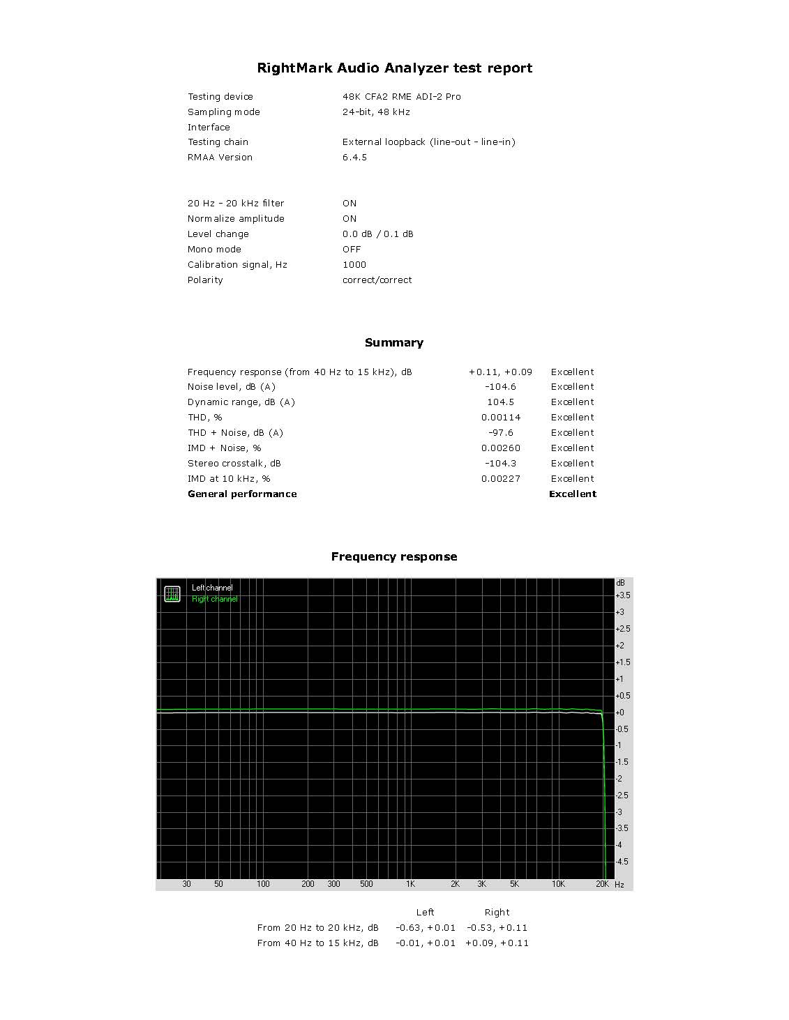
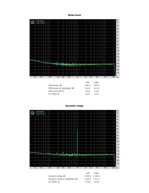
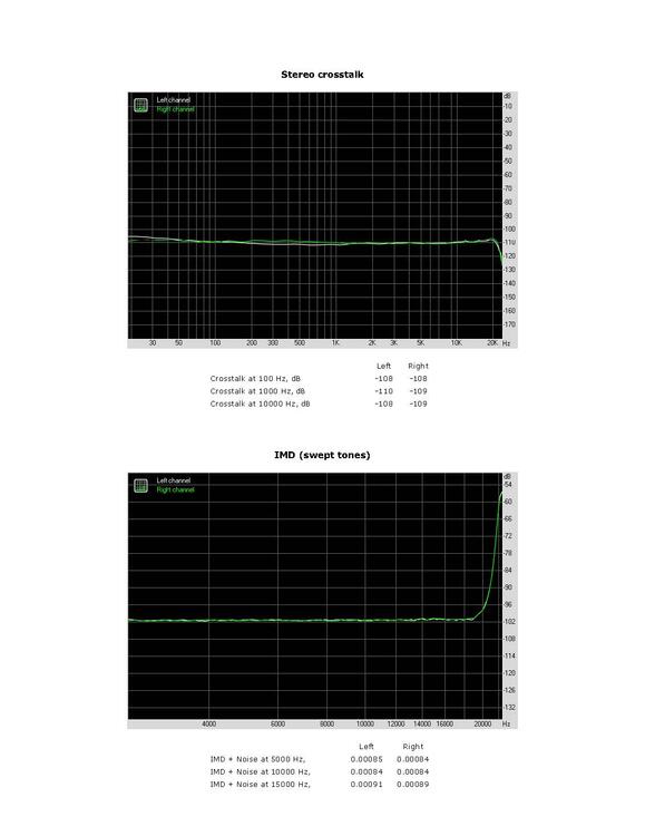
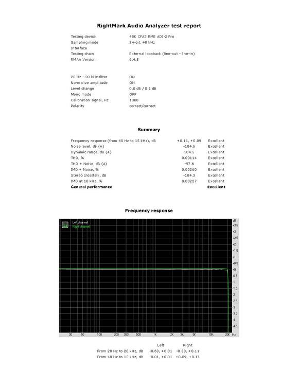
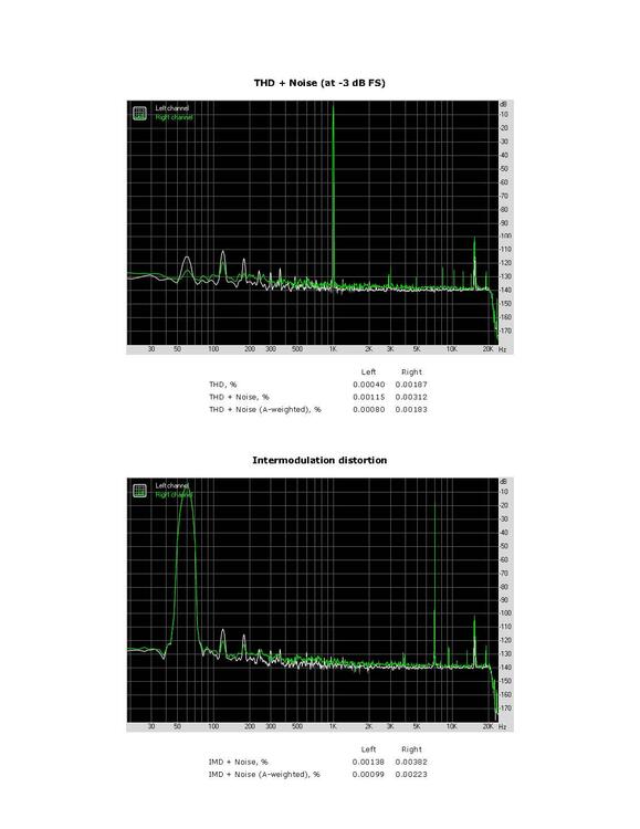
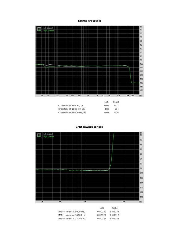
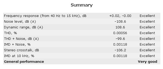
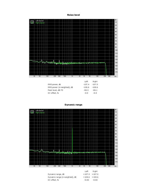
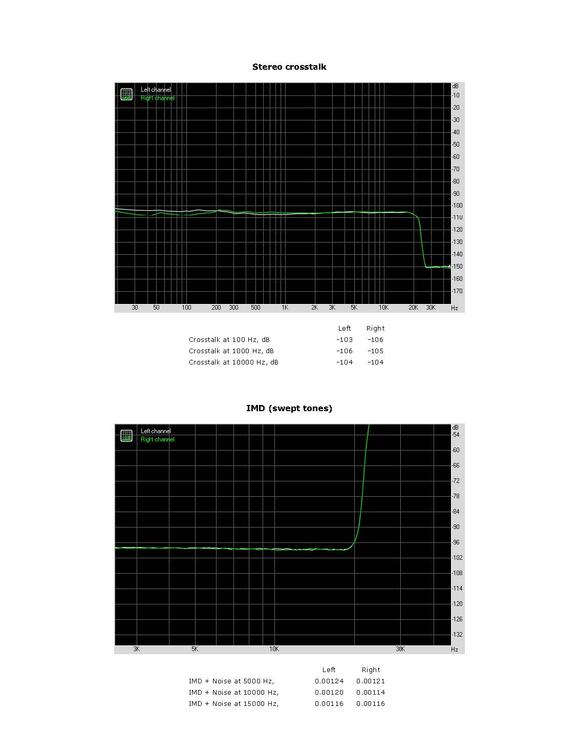
Here is the full balanced CFA2 RMAA. RightMark Audio Analyzer test _ 48K CFA2 RME ADI-2 Pro.pdf

-
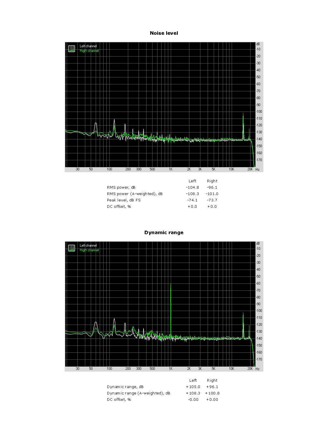
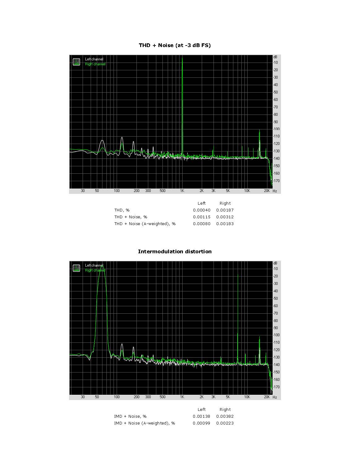
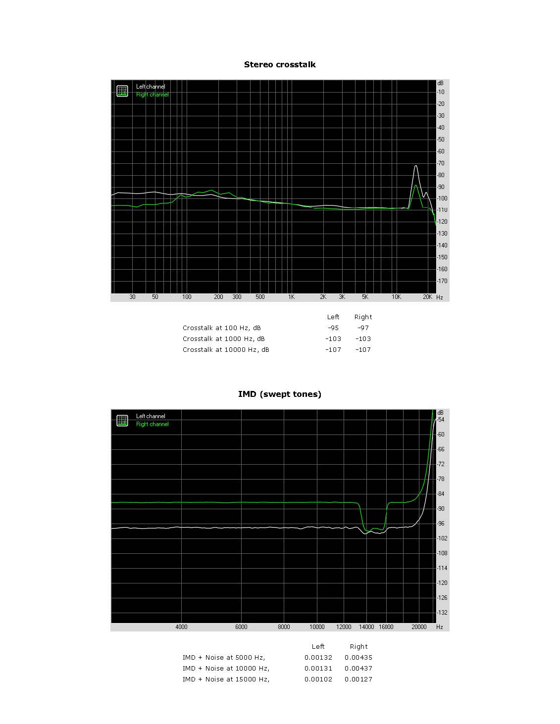
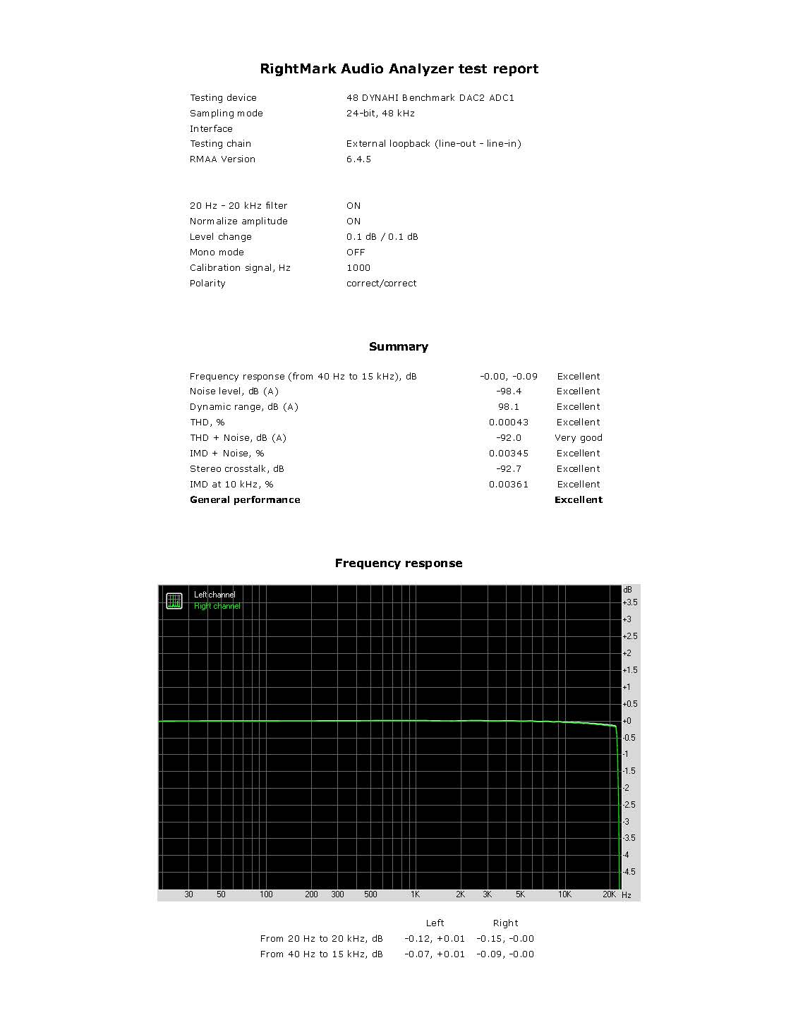
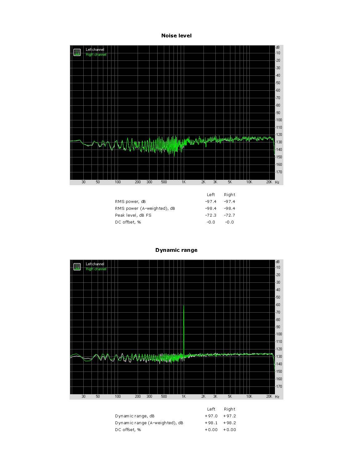
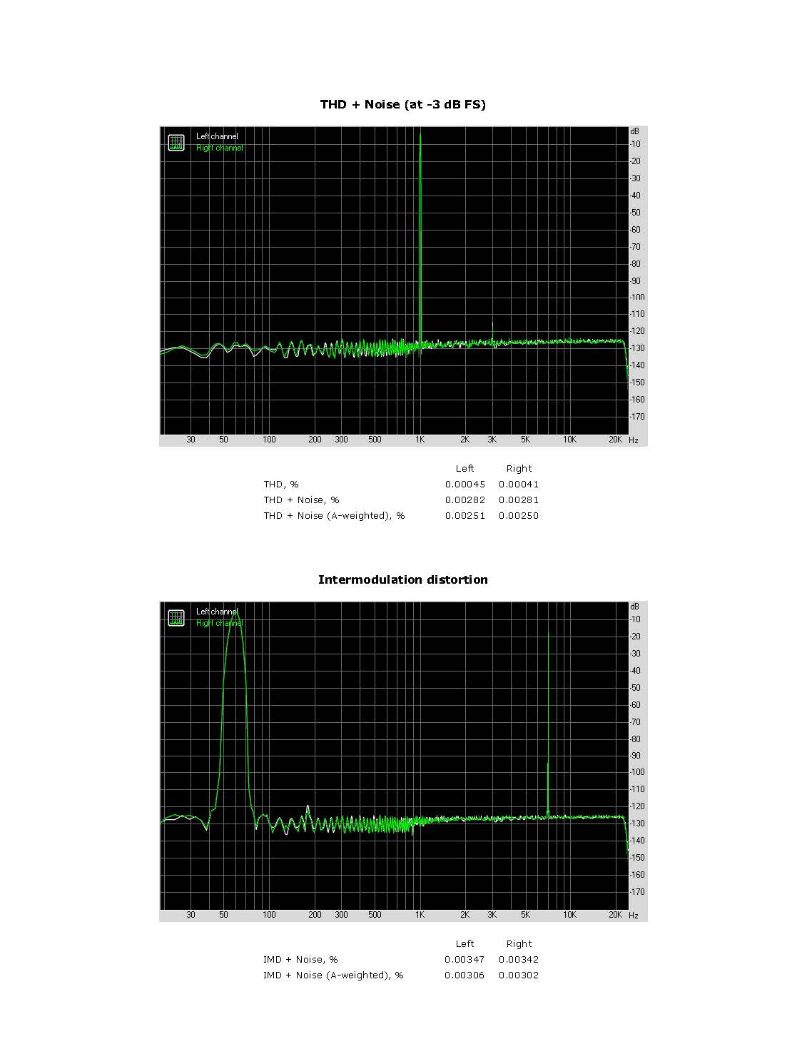
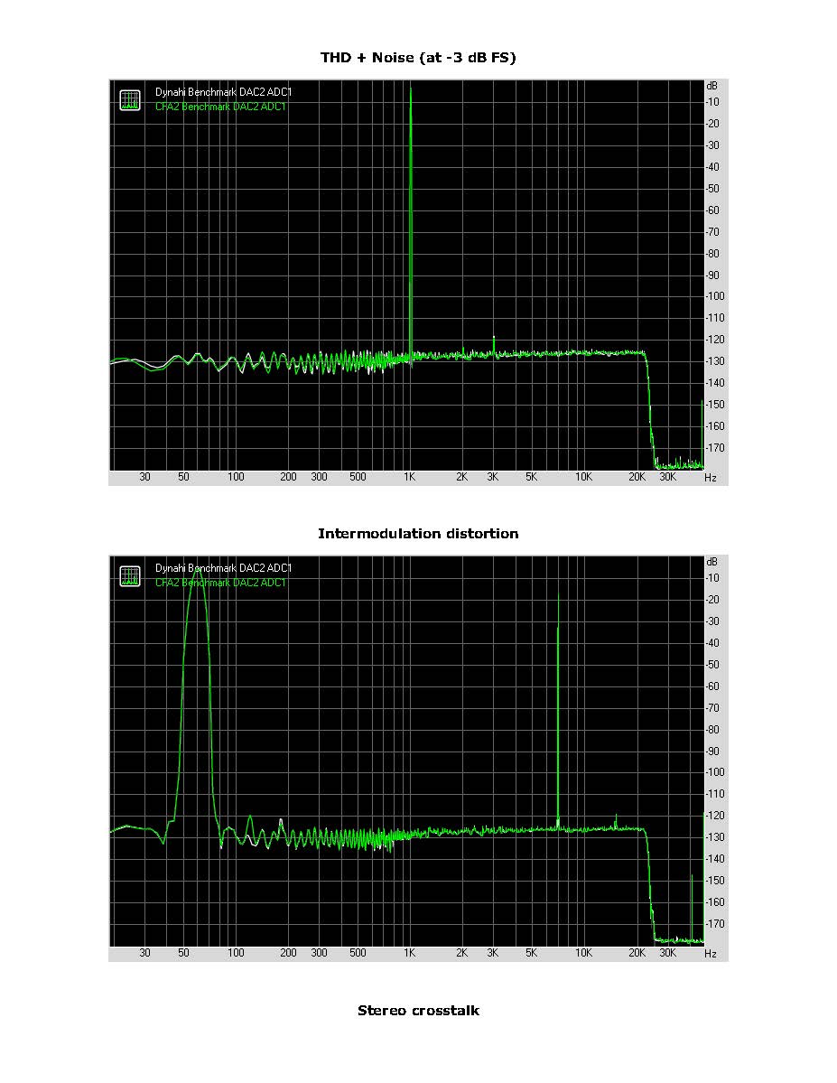
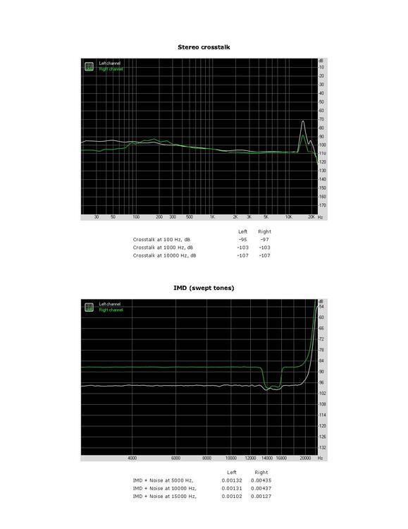
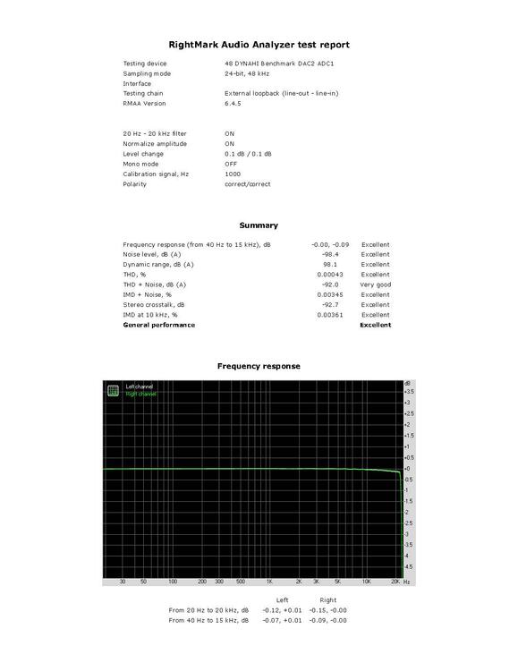
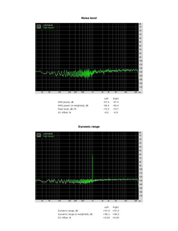
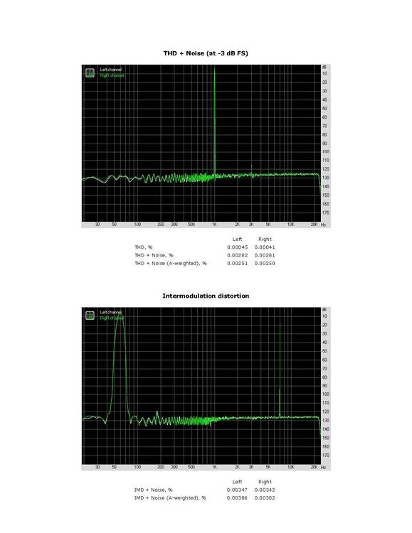
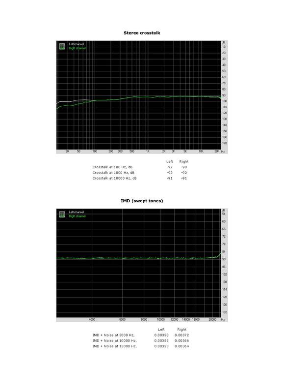
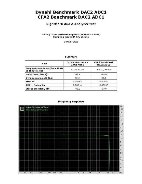
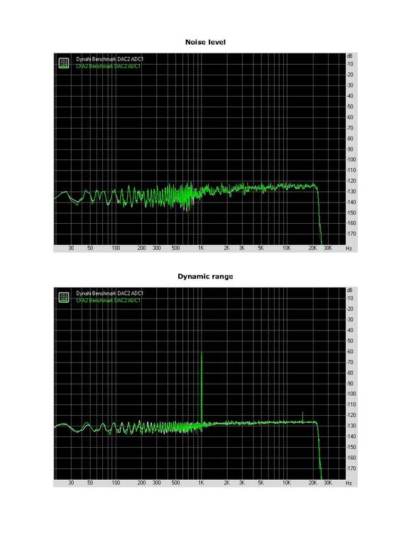
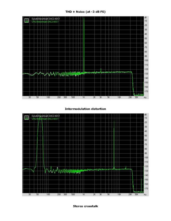
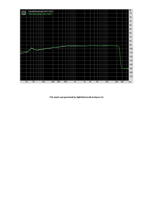
Here is the full balanced Dynahi RMAA. RightMark Audio Analyzer test _ 48 DYNAHI Benchmark DAC2 ADC1.pdf
-
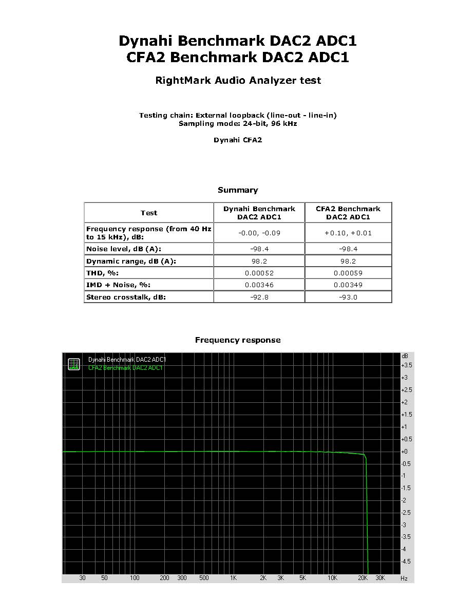
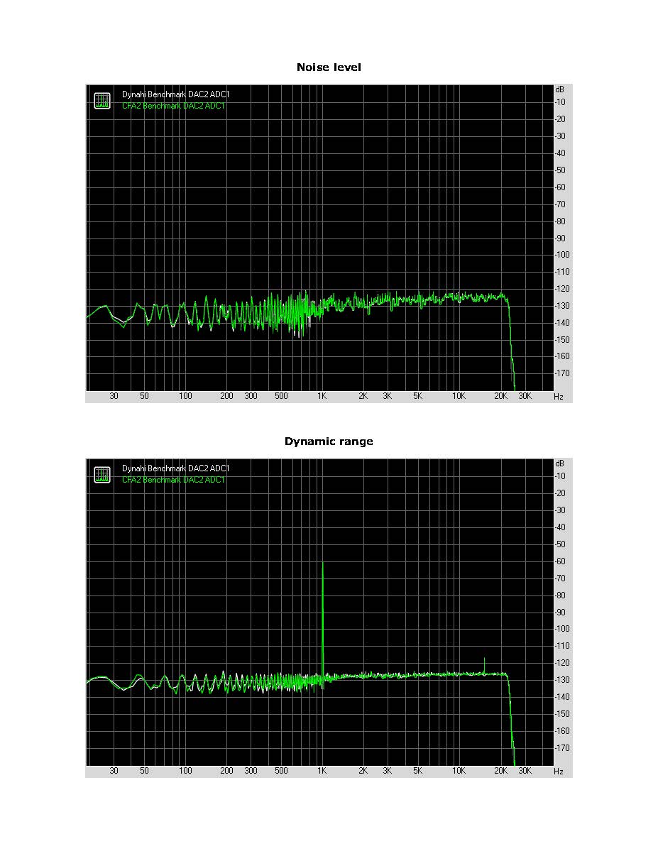
Here is a RMAA comparison of my full balanced Dynahi and full balanced CFA2. RightMark Audio Analyzer test_ comparison.pdf
-
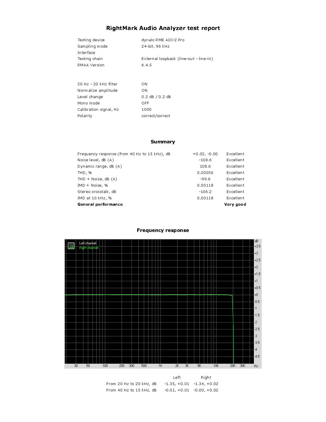
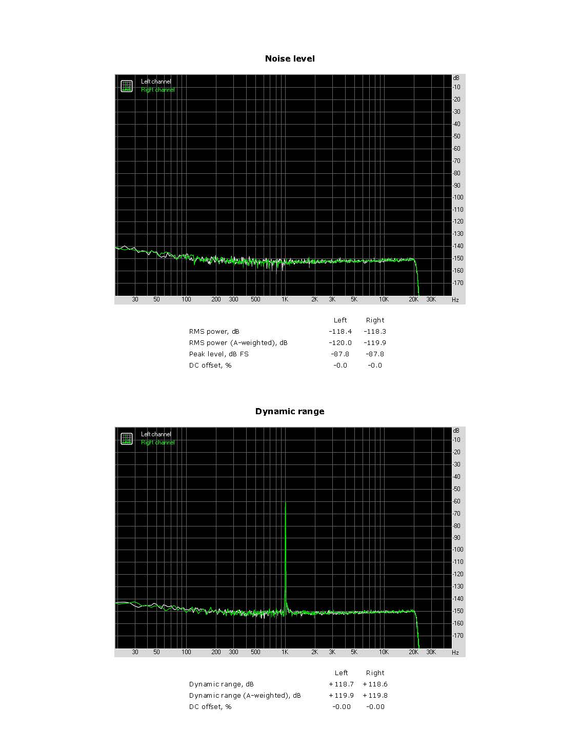
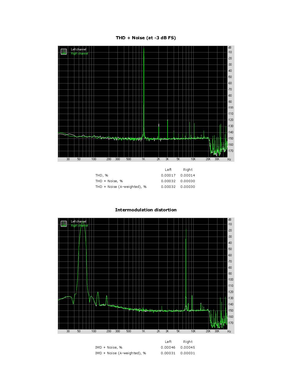
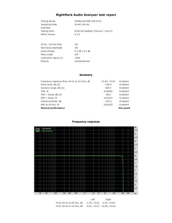
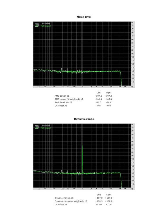
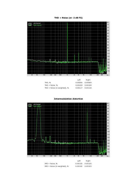
Here is the balanced Dynalo with 220 ohm loads RMAA test with RME ADI-2 PRO. Signals levels set to RMAA test levels as before. RightMark Audio Analyzer test _ 220dynalo RME ADI-2 Pro.pdf
-
These are just balanced XLR cables in and XLR cables out of the dynalo. No added loads. I'll look into adding loads.
-
Tested my balanced dynalo with the rme adi-2 pro today. The balanced dynalo is built on dip 16 sockets in 2004. Loos like the price drop of the rme adi-2 pro fs r be was only for 1 week, now it is $1999. RightMark Audio Analyzer test _ dynalo RME ADI-2 Pro.pdf


-
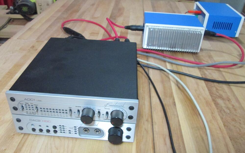
Found a new ADC & DAC device for testing my CFA2 amps with RMAA. The RME ADI-2 PRO FS R Black Edition has a recent price drop to $1699. Here it is testing one foot XLR balanced cables. It is much better than my older Benchmark ADC1 & DAC2. I'll test my CFA2 dual balanced mono amps soon. RightMark Audio Analyzer test _ RME ADI-2 Pro.pdf

-
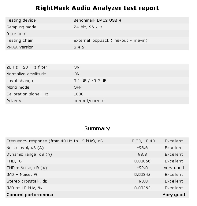
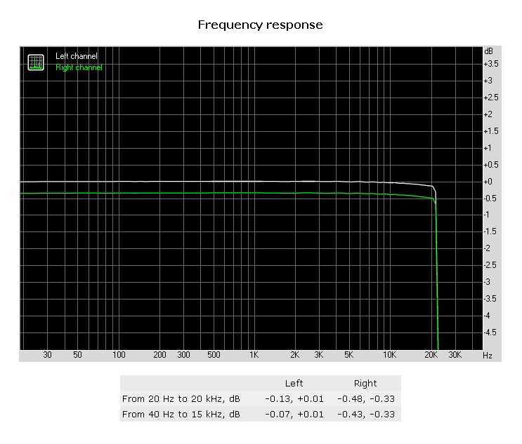
I completed the first balanced mono CFA2 amp, so I ran RMAA on it. The DAC2 balanced output right channel goes in on a XLR 2 foot Mogami 2534 cable and outputs on a 1 foot XLR cable to a Benchmark ADC1 USB. The left channel goes in a XLR 2 foot cable and a 1 foot XLR cable to the ADC1. This compares the CFA2 balanced mono to the cables. I had to set the ADC1 left channel to 10 dB gain to equal the CFA2 gain which shows 0.3dB lower than the left channel. This results in the CFA2 balanced mono gain at 9.7 dB.
-
Only one of four channels is up and running so three more channels needed to complete the full balanced system.
-
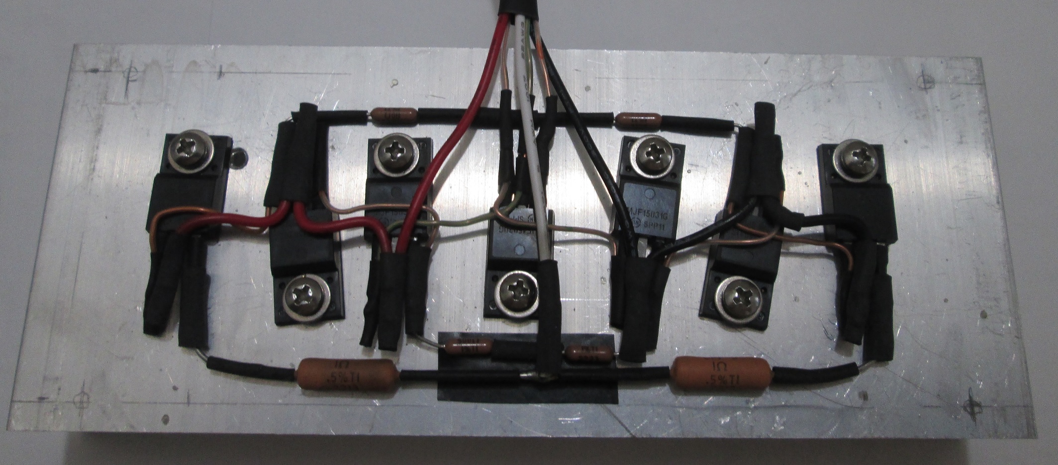
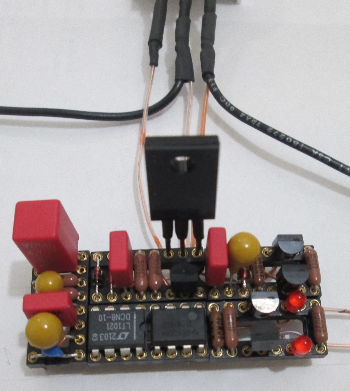
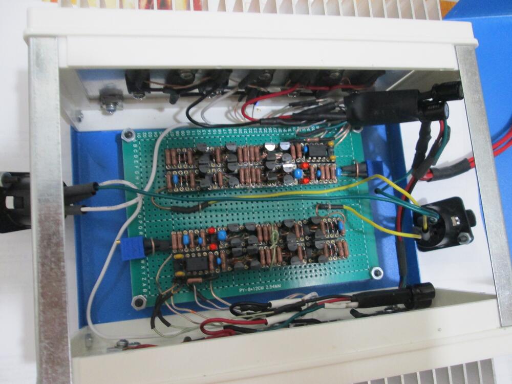
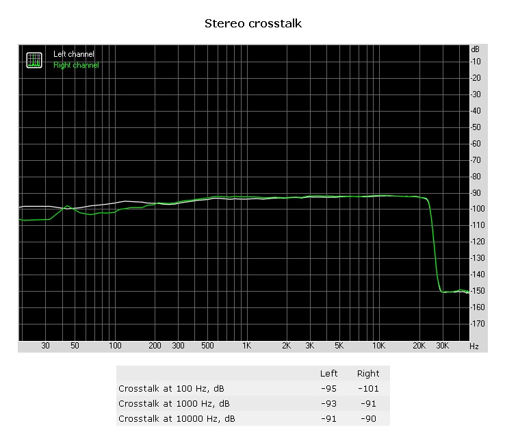
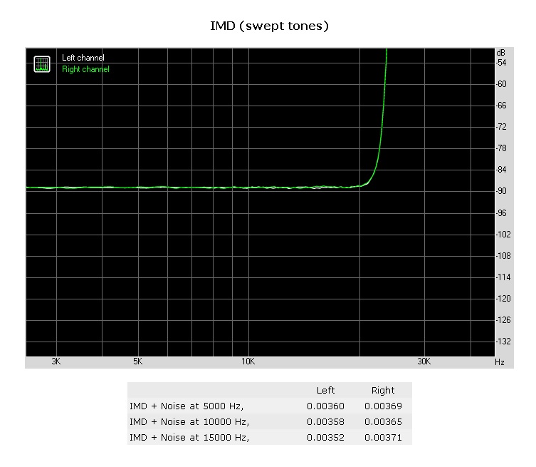
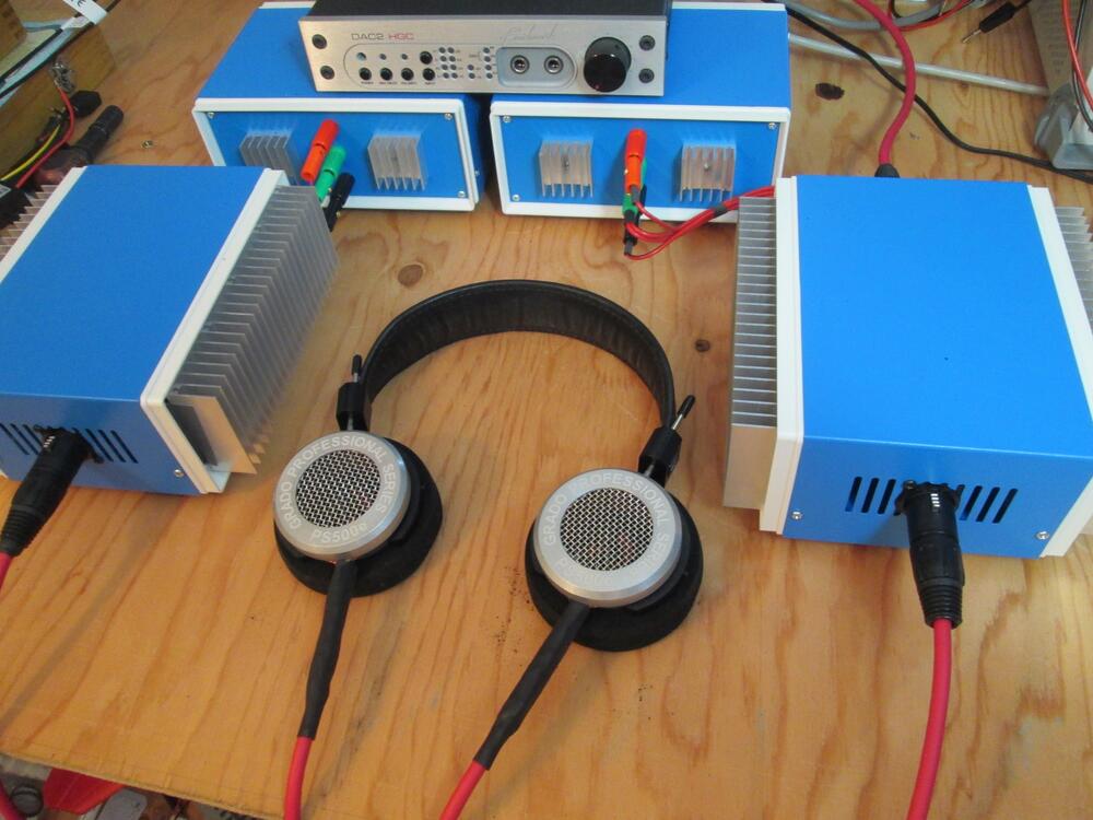
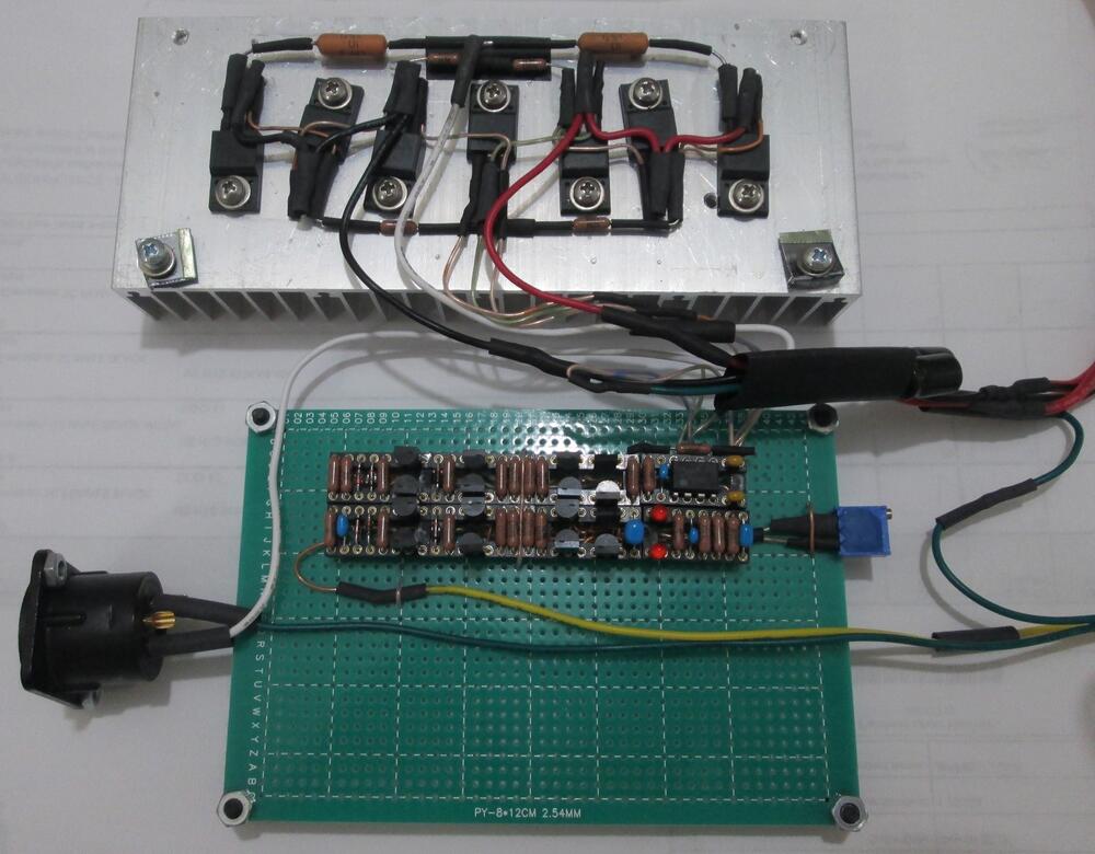
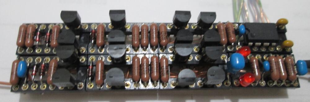
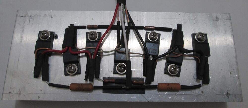
Here is my CFA2 built on dip 16 sockets as 2 balanced dual mono amps with 2 GRLV power supplies (also built on dip 16 sockets). Balanced input is from a Benchmark DAC and balanced output is to Grado PS500e with Mogami quad 2534 cable (each amp cabled to each ear). There are eight sockets with 125 pins used (3 pins are not used on the opamp) and 40 wires. Six wires go the the heatsink components. First channel is running 150 mA bias and DC offset was 30 mV without the opamp, 0.2 mV with it. Still have to build the other three channels.
-
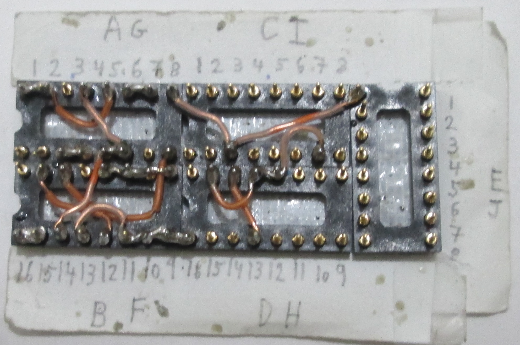
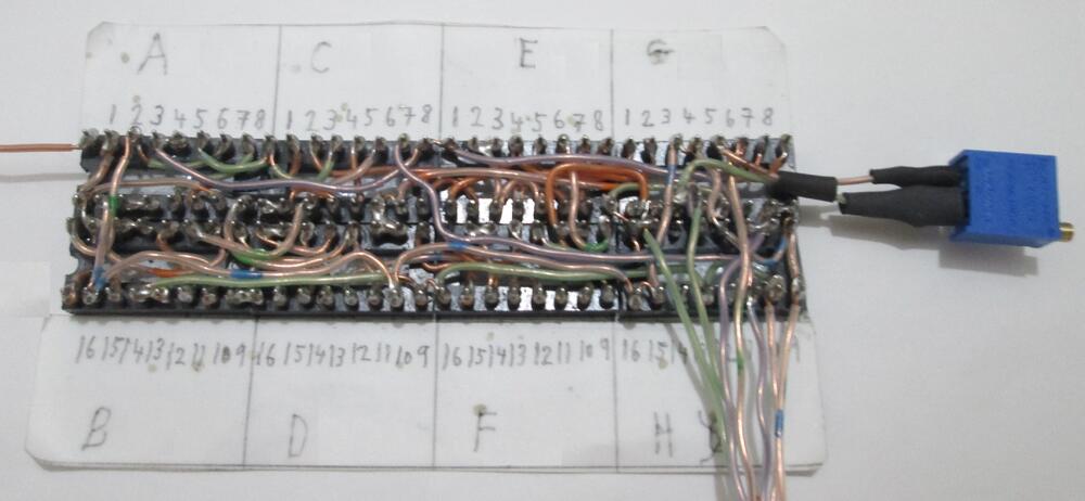
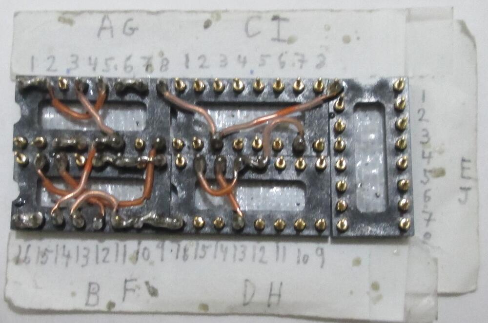
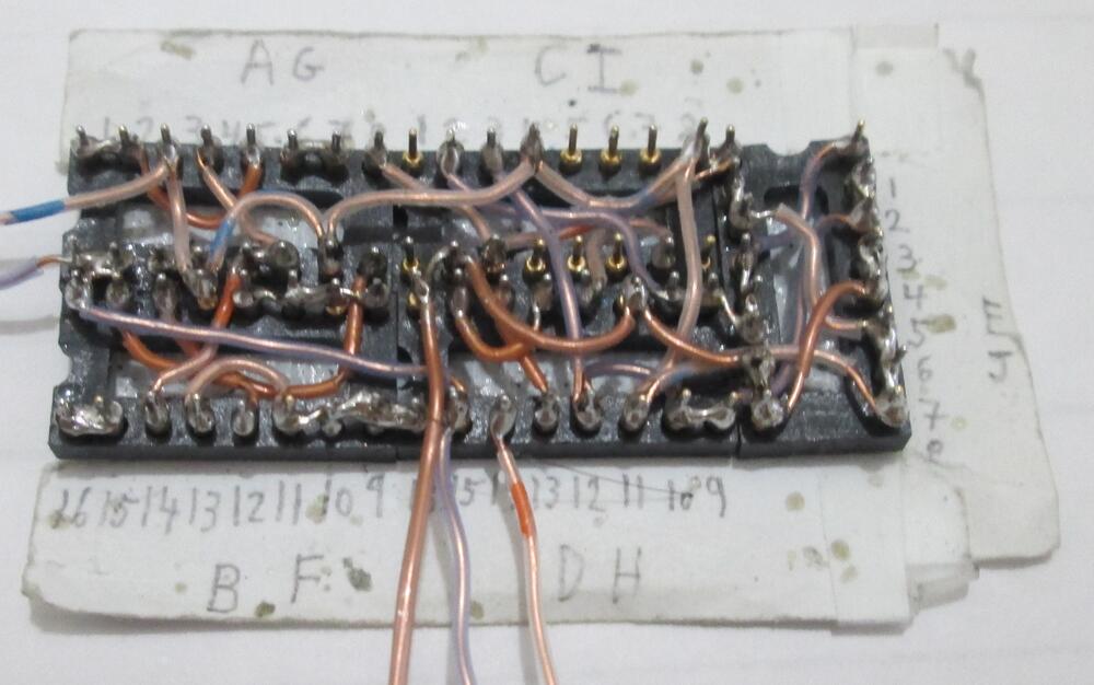
copy the following text into notepad for proper spacing format grlv dip 16 layout +30 volt ----A---------B---- | R16 | R1 | |D9+ D1+|Q6E Q3E| |D9- D1-|Q6B Q3B| |Q14C Q1E|Q6C Q3C| |Q14B Q1B| R3 | |Q14E Q1C| + D4 - | | R2 | - C7 + | | R19 | C11 | ------------------- ----C--------D----- |1 8|Q8D Q9B|Q4B | U1 |Q8G Q9C|Q4C D11- | |Q8S Q9E|Q4E D11+ |4 5| R11 | |1 8| R20 | | D6 | C .01 | | | + D - | |4 5| - D + | -------------------- -------------------------------- |C5 C9- C12 C16- R8 R7 C6+ C4.7| E | |C5 C9+ C12 C16+ R8 R7 C6- C4.7| -------------------------------- -30 volt ----G---------F----- | R4 | R15 | |Q10E Q11E|D2- D8-| |Q10B Q11B|D2+ D8+| |Q10C Q11C|Q2E Q13C| | R6 |Q2B Q13B| | + D6 - |Q2C Q13E| | - C13 + | R5 | | C14 | R22 | -------------------- ----I---------H----- Q7B|Q5B Q12D|1 8| D10+ Q7C|Q5C Q12G| U2 | D10- Q7E|Q5E Q12S| | | R12 |4 5| | R21 |1 8| | C .01 | D7 | | - D + | | | + D - |4 5| --------------------------------- |C4.7 C10+ R10 R9 C3+ C15 C8+ C4| J | |C4.7 C10- R10 R9 C3- C15 C8- C4| --------------------------------- wirelist +30 volt 24 AWG solid wire 1. A6 A7 2. A14 A13 3. B16 B15 4. B2 B12 5. B3 A9 6. D3 D13 7. A1 A2 A5 8. A8 C14 E16 9. B5 B6 B7 B8 10. A4 A11 A12 A14 11. D2 D4 D5 C10 12. B13 B11 B10 B9 D16 13. E1 D7 D8 E11 E12 E13 C2 14. C3 D12 D10 D9 E3 E2 15. (C2-) A3 B4 A10 C4 C8 D11 E8 E7 E6 E14 E15 16. (C2+) A16 A15 B1 D15 (Q4C) (D11-) 17. E5 E4 E10 E9 D6 D1 C15 (Q4E) (D11+) 18. D14 (Q4B) stranded 20 AWG wire (Q4C) (C2+) red (Q4E) output terminal pos red (C2-) output terminal gnd grn wirelist -30 volt 24 AWG solid wire 1. F10 F11 2. F3 F4 3. G1 G2 4. G5 G15 5. I4 I14 6. G14 F8 7. F16 F15 F12 8. F13 F5 F6 G3 9. G9 G10 G11 G12 10. G4 G6 G7 G8 I1 11. F9 H14 J9 12. I16 I12 H8 13. H3 I5 I7 I8 J6 J7 14. H2 I10 I9 J14 J13 J12 J8 15. (C1+) F14 G13 F7 H15 H10 J11 J10 J3 J15 J16 I6 16. (C1-) F1 F2 G16 I2 (Q7C) (D10+) 17. J1 J2 J4 J5 I11 I13 H4 I15 (Q7E) (D10-) 18. I3 (Q7B) stranded 20 AWG wire (C1-) (Q7C) blk (Q7E) output terminal neg blk (C1+) output terminal gnd grn copy the above text into notepad for proper spacing format
-
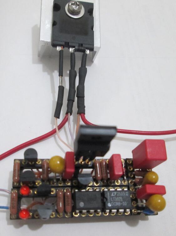
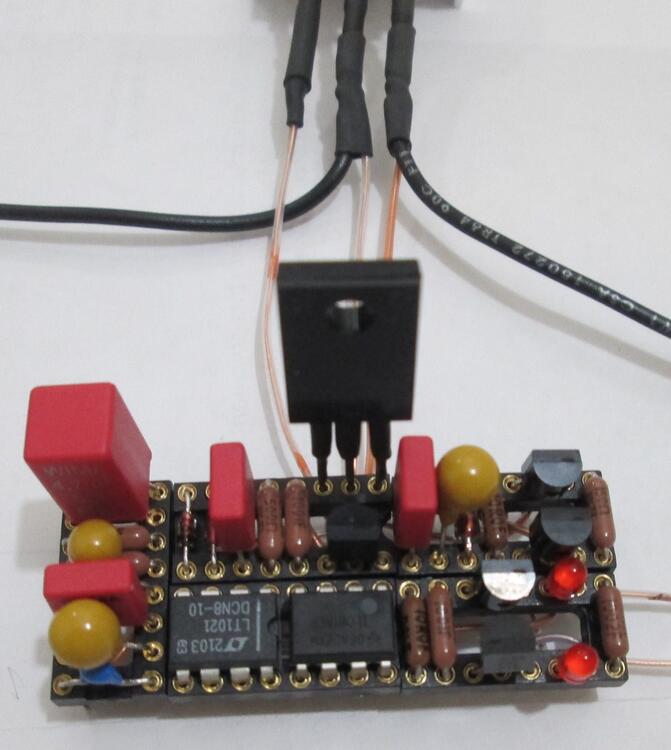
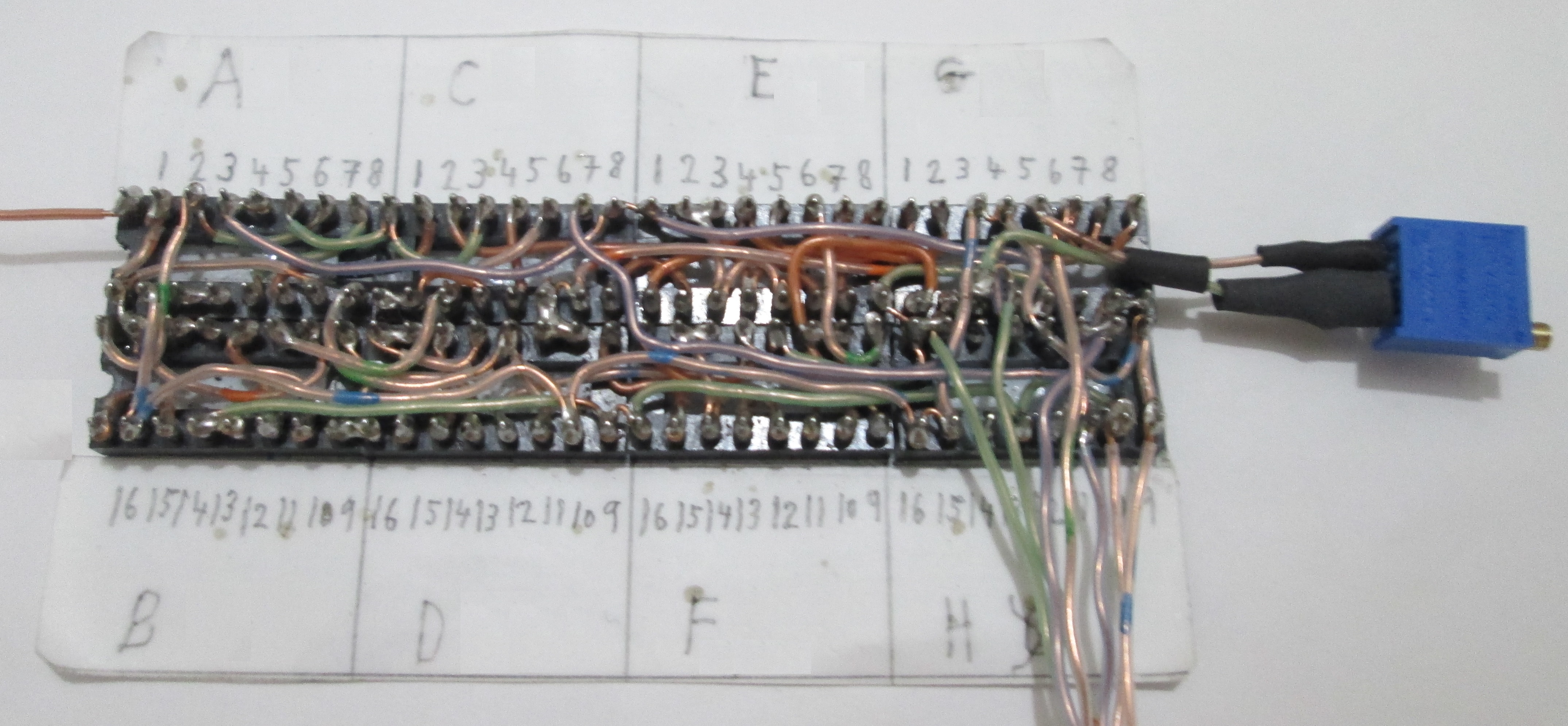
The first has the first 12 wires and the second has all 18 wires. Attached is the layout and wire lists. That is 2" duct tape holding the sockets together for soldering. The wire is from solid 24 awg cat 5 wire. I could not find any opa134pa op amps so I used tl081bcp, also tried lm318p which also works. The 47 uF caps has the 9.1 zener voltage and 10 volt ref voltage so I used 16 volt caps Used zener diode 9.1v 1/2w 78-BZX55B9V1 to fit into the sockets. grlv dip 16 layout.zip
-
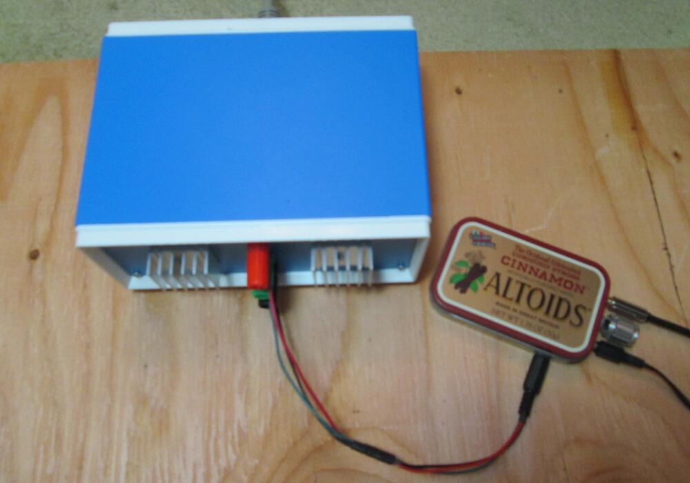
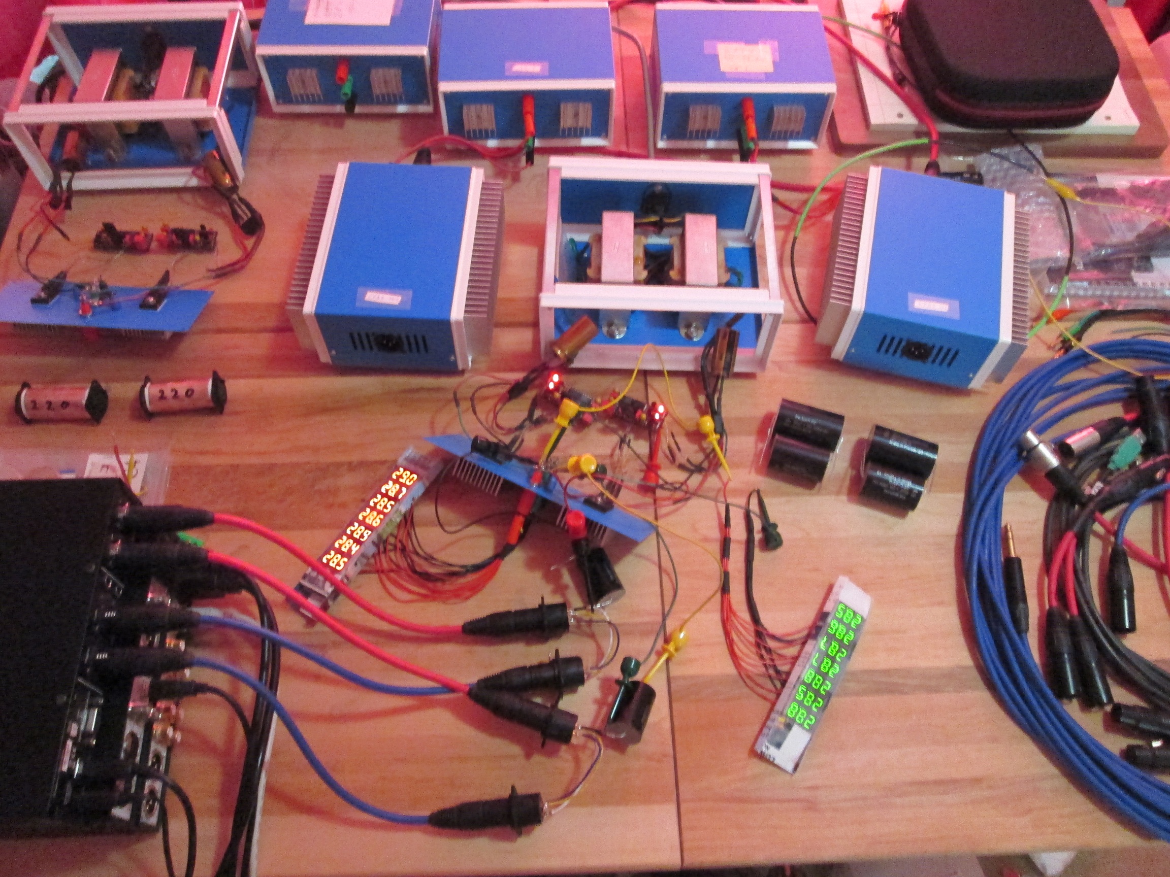
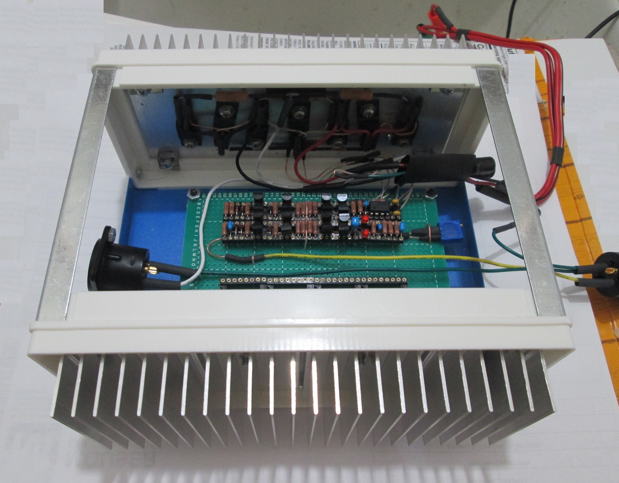
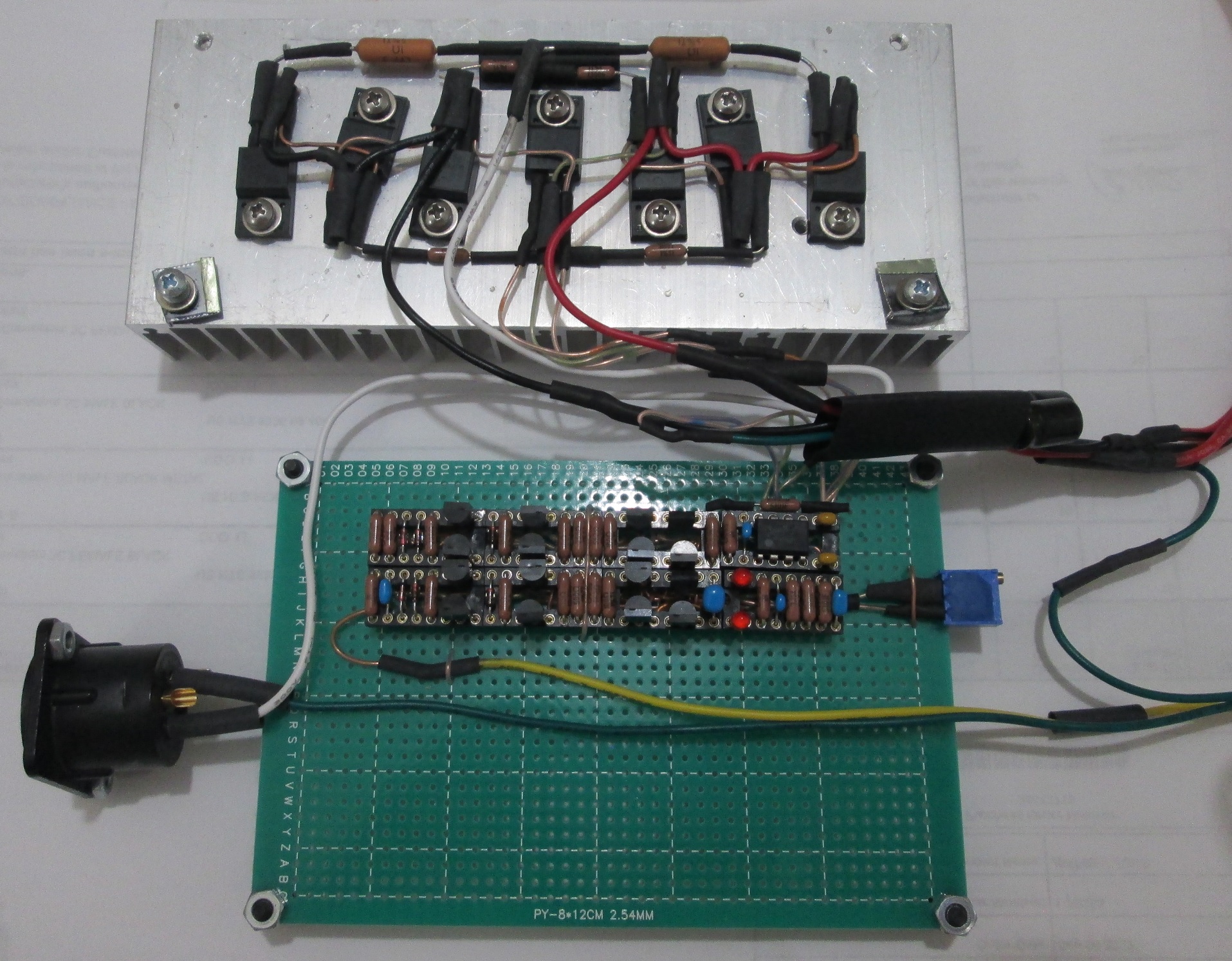
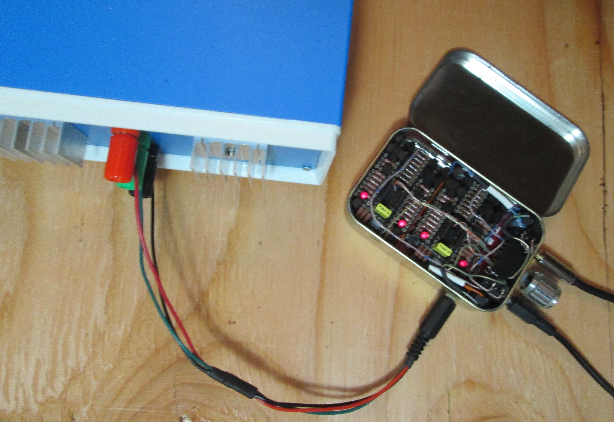
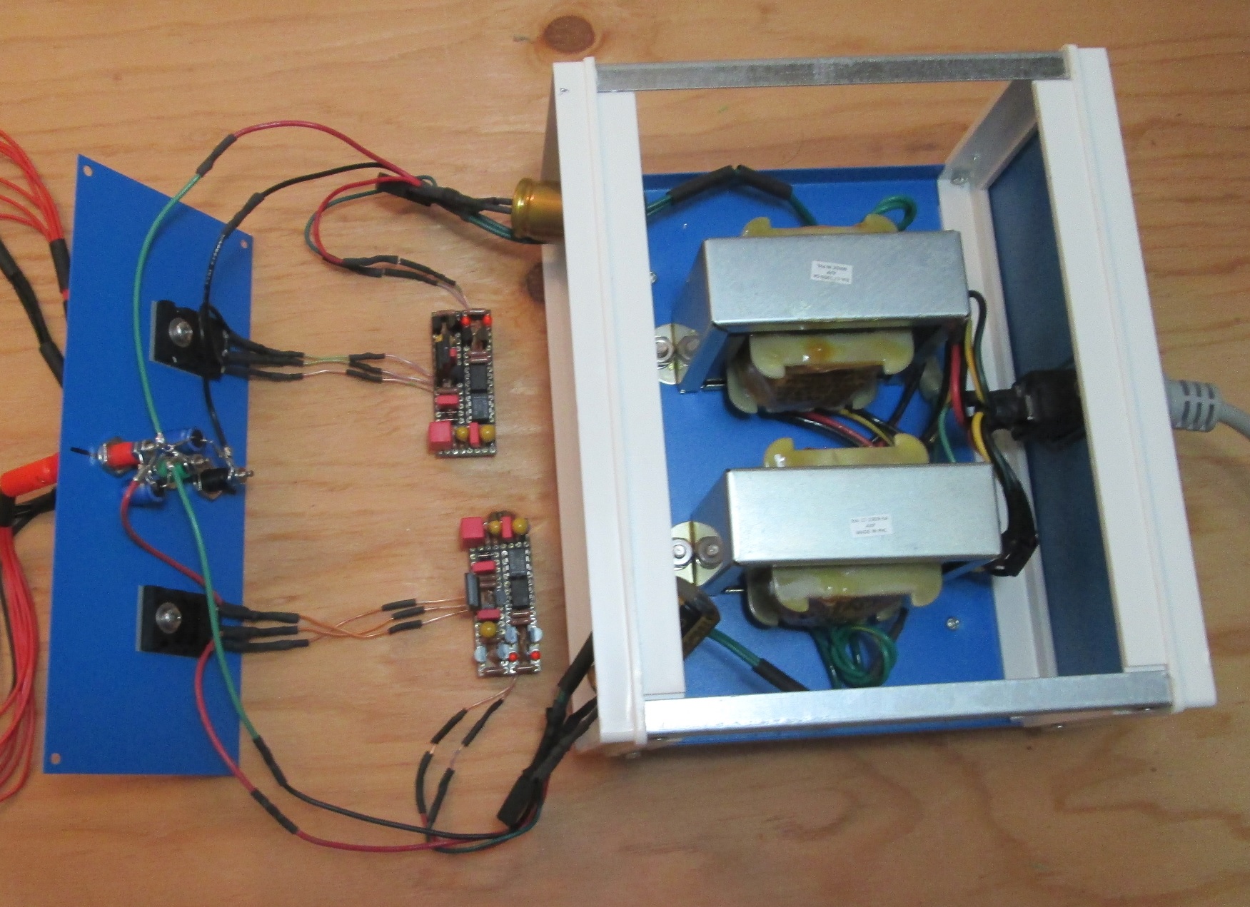
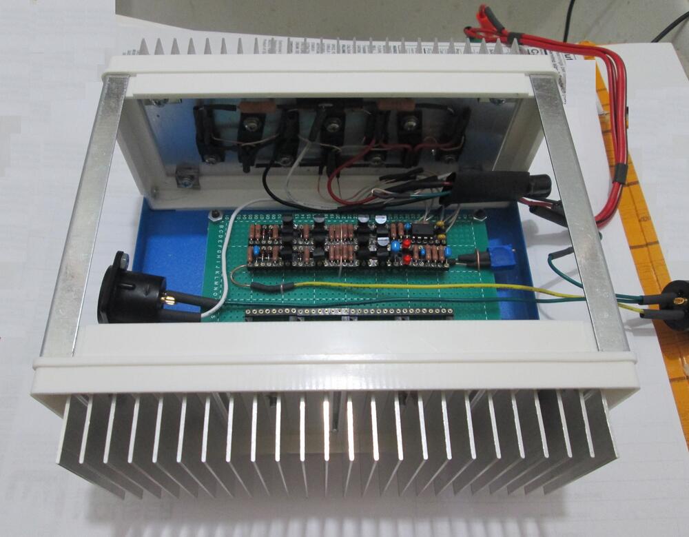
Here is my grlv power supply built on dip 16 sockets for my dynalo amp, also built on dip 16 sockets and put in an Altoids tin. It outputs +/- 16.7 volts using a couple of 16 vac 30 va transformers which puts 23 vdc into the grlv module. Also built a +/- 30 volt supply with a couple of 25.2 vac 50.4 va transformers and it puts 37 vdc into the grlv module. A second +/- 30 volt supply is pictured open. These are for my balanced dynahi, also built on dip 16 sockets. The grlv dip 16 module has 5 sockets on each side. There are 18 wires connecting 71 pins, each pin has only one wire on it, 9 pins are not used on the ICs. Parts layout and wirelist make it easy to reproduce.