Satyrnine
-
Posts
132 -
Joined
-
Last visited
Content Type
Profiles
Forums
Events
Everything posted by Satyrnine
-
Thanks! Yeah, impossible to beat that price! I had my boards made at oshpark. While I've had great luck with them, maybe something is up with the boards themselves.
-
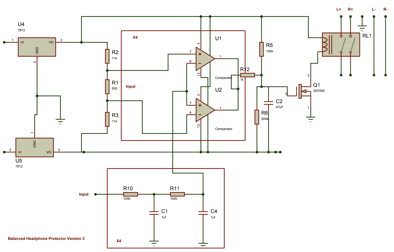
Thanks for the reply! In my case the noise is on the 30v rails, not the protector board ins/outs. I have a dual mono CFA3. All I need to do is connect the board to a grlv also powering one channel of the CFA and it injects the noise into that side of the CFA3, audible in headphones that are connected directly to the CFA3 outs, nothing connected to protector board ins/outs. So it's adding the noise to the grlv, which is then audible in anything also connected to that grlv. And yes, there's a number of caps and diodes on the board that aren't in the drawing. There's a diode across the relay coil. Thank You!
-
Well I made progress on my noise issue. There is no noise present if I remove Q1, the mosfet that turns on the relay and instead connect the relay to ground directly, effectively hardwiring the relay on. That tells me that the noise likely (?) isn't from an over-taxed 7812 regulator being fed 30v. Narrows it down to Q1 or the comparator circuit driving it... right?

-
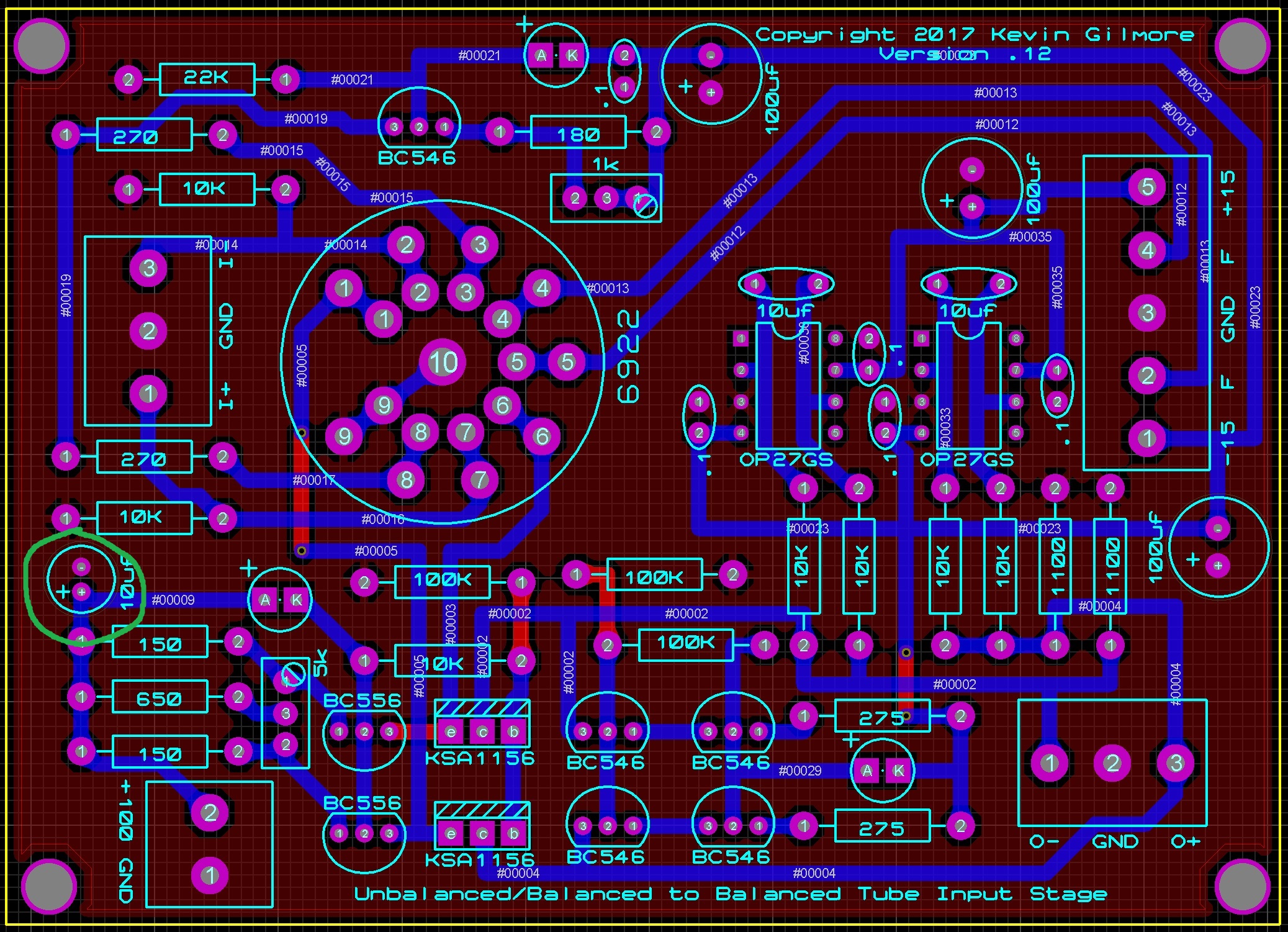
unbalanced/balanced to balanced tube input
Satyrnine replied to kevin gilmore's topic in Do It Yourself
Edit: I'm considering not running a HV delay at all, and relying on headphone protector board for delay and DC protection. A "standby switch" necessity is widely overstated, especially at the rather low 100v B+ we're dealing with in this circuit. Some even argue that hv delay (for long periods) can cause cathode poisoning. In my build, getting the delay working would be mean an additional 30vin to 12vout reg board as well as a 12v 555 delay board to operate the cpc relay. (can't find a 30v delay board without a noisy buck converter). KISS principle I figure. Any thoughts? -
and now for something completely different part 3
Satyrnine replied to kevin gilmore's topic in Do It Yourself
Please don't kill me for asking this: Can anyone suggest the best method to connect a subwoofer with SE or speaker-level inputs only to a CFA3? (specifically ubal2baltube boards into 4x cfa2) I imagine the sub inputs grounds are not floating, which obviously presents a problem. Maybe a 15k 1:1 audio transformer tapping signal after volume control? aka a "DI box"? Or maybe something like this paralleled to CFA inputs post-volume? Am I missing an easier method? -
Now that my CFA3 tube hybrid is nearing completion, I'm trying to get my protector boards working again. I chatted with Dukei/Miroslav who's used a number of these at +/-30v, and he says he's had no troubles, so it must be a problem with the boards. I have two built and both exhibit the same noise. Merely connecting power to the board, without using the ins/outs injects noise into the power supply. Only changes from schem are the slightly higher rated G6A vs G5A relay (pulls less max current actually) and a 1n4004 vs a 1n4007, which shouldn't a problem I don't think. I'm getting +/-12v on the chip pins as expected. Regulators aren't getting hot either. My bench supply is only positive, so no easily accessible bipolar supply on hand. Would it be inadvisable to use a voltage divider on a grlv 30v rail to bring down the 30v and add some isolation just to see if that resolves? Does anyone want to sell me a pre-made protector verified to work with 30v rails? I've just about had it with this, haha! I also tried the board in a friends Dynahi at 30v, and experience the exact same noise injection as soon as power/ground is connected.
-
unbalanced/balanced to balanced tube input
Satyrnine replied to kevin gilmore's topic in Do It Yourself
Just connected the tube boards to my cfax4 and gave a quick listen, I hear ZERO noise even with vol cranked. Zero hum/hiss/anything. Still retains that CFA slam/sound but with a perfect amount of tube "flavor". Bass has definitely not suffered one bit. WOW, can't wait to get it upstairs for a long listen. Still a rats nest on the bench. I'm going to have to figure out a good way to power the hv relay for final build. Appears it needs just a few volts and low current. I wonder if a voltage divider from a +30v grlv output would work? Just using a toggle switch right now. I'll message Dukei, who's done a few tube boards. May be who you're referring to on head-fi Pars. -
unbalanced/balanced to balanced tube input
Satyrnine replied to kevin gilmore's topic in Do It Yourself
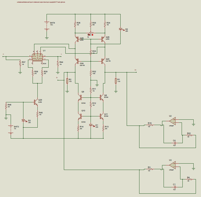
After getting these boards running, it seems to me like they bias up sort of like a dynahi. Trimpot on cathode adjusts offset up/down evenly across O-/O+, and balance balances the offset. Let me know if I'm off there. I scoped it and looks like it can take about 2.5vac per input before obvious clipping. (Using an old analog scope so not the most accurate) -
unbalanced/balanced to balanced tube input
Satyrnine replied to kevin gilmore's topic in Do It Yourself
Edit: Fixed! It was the damn socket! Two pins were somehow not connected to opamp. I reheated pins and two just fell out. That’s a first… I was measuring to solder pads not to opamp itself before. Learned something! I'm having trouble with the servos. On one board, I can get the offset almost zero WITHOUT the servo installed, using the balance pot, but as soon as I pop in the servo, I get about +3V of offset on the -O. What the hell? Here's what I've got on the -O side servos, which clearly shows something is screwy, I just can't figure out what. Voltage to ground: Working board: pin 2 (-in) 0v, pin 6 (out) 5.4v Problem board: pin 2 (-in) 3v, pin 6 (out) 28v! If I swap -O and +O servos opamps, same readings, if I swap tubes, same readings. Caps and resistors around servo measure ok. +/-30v rails checkout. What the hell? I'm sure it's something stupid. Could I have a bad transistor somewhere that'd do this only when servo installed? Any guidance would be extremely appreciated. -
unbalanced/balanced to balanced tube input
Satyrnine replied to kevin gilmore's topic in Do It Yourself
Hey Pars, I'm asking about biasing the tube on the ubal-bal tube boards, I've got the cfp boards dialed in. Thanks! On the board there's a 1k pot across r45, tail of the q29 ccs on shared cathode of the tube.
-
unbalanced/balanced to balanced tube input
Satyrnine replied to kevin gilmore's topic in Do It Yourself
How much DC offset without servo is "ok" for these tube boards? I'm finding even tubes that are "matched" can give me a pretty wide range. Over 1v difference between gnd/+O and gnd/-O, that the balance trimpot can't dial out. Some are perfectly balanced, some not so much. Do I just have to be extremely picky with matching triodes? Play with resistor/balance pot values to dial in for the particular tube? Edit: I believe this mismatch I was seeing was due to the weirdness I've got going on on this one problematic board, see comment about servo/offset below. Additionally, is a delayed hv turn on a necessity? I see about 3-4v offset before tubes start to conduct. Will the servos (opa445 at 30v) be able to handle that safely until tubes are hot? With all-tube amps, standby switches aren't usually completely necessary, but with this being DC coupled it's a whole different thing. These will be for the front of a CFAx4 Edit: I'm going with Yes, delay is required, at least if you're not using a headphone protector board with a decent delay, in which case, nbd. Offset goes too haywire on startup to be safe otherwise. Last, as far as biasing these up, is there any specific numbers I should be shooting for/recommended, or specific way I should be checking? I know a tube gain stage, but not as adept with the ccs or mirror bits at the end. Thank You! -
unbalanced/balanced to balanced tube input
Satyrnine replied to kevin gilmore's topic in Do It Yourself
Doh! That makes sense. Hindsight is 20/20. I'm sure that's my problem. Thanks all! p.s. I sourced some tasty NOS Siemens E288CC (uber 6922, 10khrs, ultra low noise, gold pin, slightly more heater and plate current) from Brent Jesse for this. Been listening to the bare 4x cfa2 (mindblowing by itself, loves Susvaras), excited to try this with it! -
unbalanced/balanced to balanced tube input
Satyrnine replied to kevin gilmore's topic in Do It Yourself
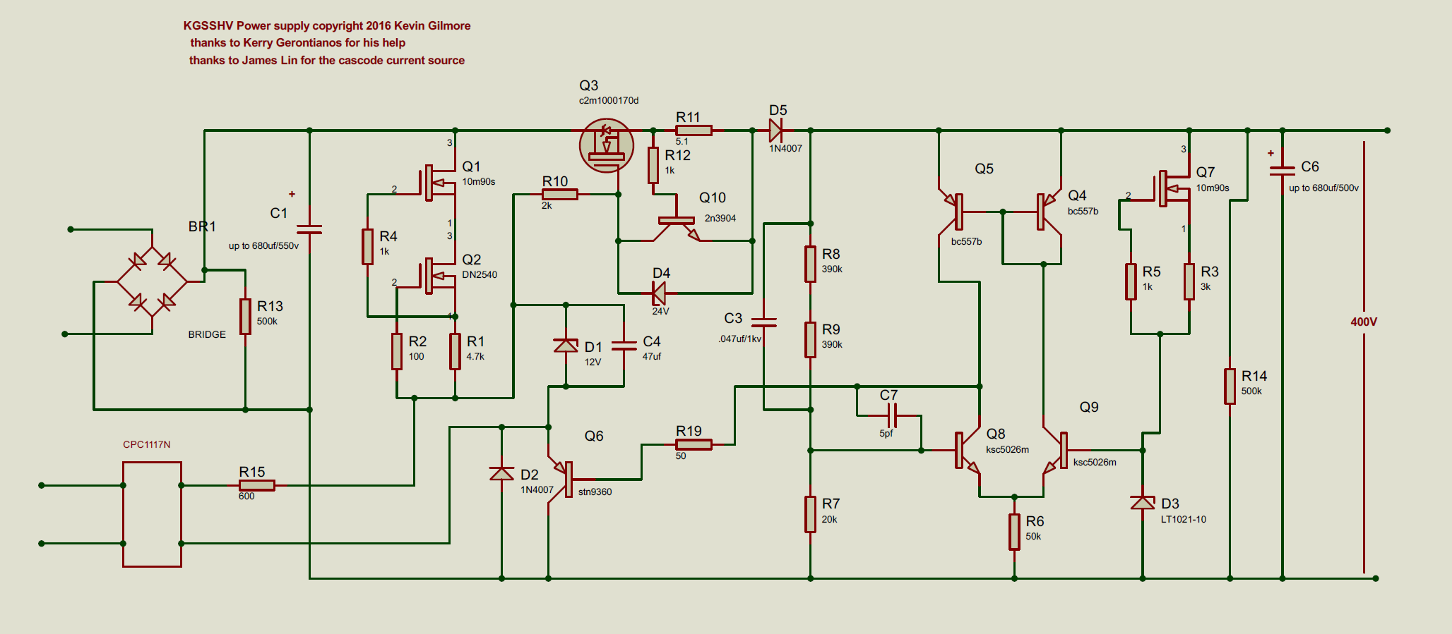
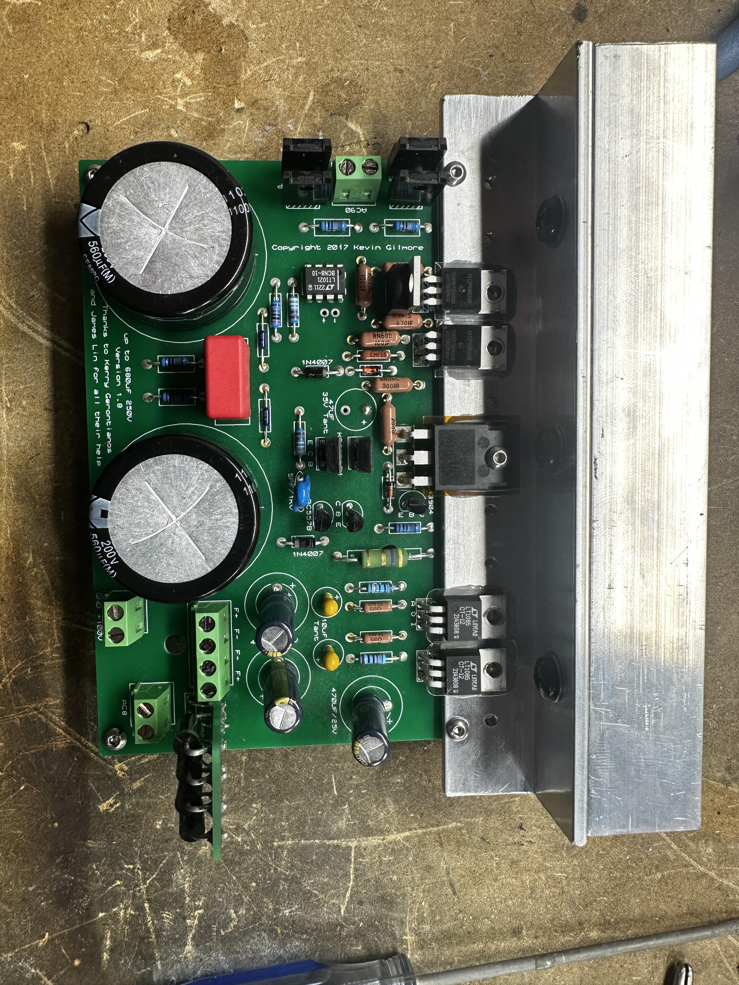
Getting the grhv100 up and running. Hoping someone could provide guidance. Cliff notes in red. Having trouble getting voltage out of the regulator Q3. I've got 3v on pin 1, 130v on pin2(in), and nothing on pin3(out). Seems it's not being turned on? The normally-closed cpc1117N relay is left unpowered, which should be "on" state... right? Schem for the 400v version below, I couldn't find one for the 100v version specifically, but very similar I believe. grhv100 board identical to mine, except I've not added a .5R 10W resistor between filament bridge+ and first cap, and changed first cap to 1000uf. Obv that's irrelevant in this case. I subbed bc556 for the bc557’s. As shown below, Q10 (adjacent to the HV regulator) is in backwards, that's been fixed, although I DID use the same part. I did power it up backwards, discovered, then flipped it. Could this be the culprit? No spares on hand. Can I sub a bc546? Diodes around it check out. Tests ok in a transistor tester.
-
unbalanced/balanced to balanced tube input
Satyrnine replied to kevin gilmore's topic in Do It Yourself
Before I got a proper bench supply, I used to use this method for getting different voltages for anodizing Titanium various colors, haha! -
unbalanced/balanced to balanced tube input
Satyrnine replied to kevin gilmore's topic in Do It Yourself
Trafo from Toroidy arrived! I'm getting about 7.2vdc for filaments, loaded. I'm currently using the stock 121R(series)/510R(to neg) resistors on the adjustable regs. Can anyone help me with the math to dial that in closer to 6.3vdc? 200R/510R? I assume that'd be easier on the regs than 121R/450Rish would? -
and now for something completely different part 3
Satyrnine replied to kevin gilmore's topic in Do It Yourself
Bravo! Looking excellent! Sure going to be a smaller package than the 2x 2U chassis I'm working on, haha! I'm adding the ubal2baltube input, plus 4x cfa2, but still! -
and now for something completely different part 3
Satyrnine replied to kevin gilmore's topic in Do It Yourself
I'm hoping to run a sub with my balanced cfa3. The sub only has SE RCA inputs, or speaker level inputs. Would this Jensen transformer (special low freq edition designed for sub inputs) jt-112p-2hpc.pdfbe a good way to get a SE sub output from the cfa3? Was thinking I could tap the signal after the volume control, before the CFA boards. Thoughts? JT-112P-2hpc - 39k:47k - 1:1.10, +20dbu max input. -
unbalanced/balanced to balanced tube input
Satyrnine replied to kevin gilmore's topic in Do It Yourself
Definitely! I'm able to make plans/drawings to get all my holes drilled/tapped if I wanted to, but since I'm not planning on making multiples, I decided to just do all of that by hand, and have just the main front/rear panel cutouts done by Modushop. All the heatsink interface will be done by me by hand. I figure there are too many variables to be 100% sure with my placement until I have the chassis on-hand. What I do is drill the mounting holes first, then place the transistor without any thermal pad/compound, bend leads as needed, THEN apply thermal pad/paste, insert, solder. Def way more time consuming that having pre-drilled, pre-bent. I'm using shoulder washers for anything with a exposed tab/hole, to verify no continuity. I've found that forming taps tend to be less troublesome with aluminum than fluted cutting taps as well. -
unbalanced/balanced to balanced tube input
Satyrnine replied to kevin gilmore's topic in Do It Yourself
Thanks Pars, yeah that's what I meant with "custom". Audio Supreme was just under $250 (incl shipping) and 2ish month wait minimum. In 2x45vac (for 90vac) + 8vac. I'm not opposed to the cost if it's the only option, but off the shelf hammond toroids (if they actually made them in 90v and 8v) would be a fraction of that. Even if I had cheap temporary lam core iron to test with while waiting on toroidy would be great. Strange there's so few options in those two voltages. I'll just be patient I guess. Ughh. Haha! -
unbalanced/balanced to balanced tube input
Satyrnine replied to kevin gilmore's topic in Do It Yourself
90vac transformers under 1M /s VA seem to be unobtanium. Think I can get away with 80vac and some low dropout diodes for the grhv100? Next available option is 100vac. Otherwise it's ~$250+ custom and 2-3 months wait min. Any off-the-shelf options I'm missing? Bonus points for 8vac + 90vac in one! -
unbalanced/balanced to balanced tube input
Satyrnine replied to kevin gilmore's topic in Do It Yourself
Very good point, agreed! Always check for (lack of) continuity from device to sink before powering on as well, obviously. -
unbalanced/balanced to balanced tube input
Satyrnine replied to kevin gilmore's topic in Do It Yourself
Oh hey, something I can answer! I'd give it a 6-7. My electronics experience is mainly with HV tube gear. I'm a repair tech and do custom builds, so lots of experience there. While Alum Oxide definitely IS better, we're only talking about 100v here, I don't think mica will give you any trouble. Be smart with thermal paste, as some types CAN be conductive and can cause a "bridge" if you're too generous with it. I've seen far worse than mica insulating 500+V successfully, but you should be OK. It's typically 600V insulation per mil of thickness. -
unbalanced/balanced to balanced tube input
Satyrnine replied to kevin gilmore's topic in Do It Yourself
Grhv100 nearly ready to test, waiting on 90/8 trafo from toroidy and some shoulder washers for the to-220’s. Sink is temporary. Added discrete bridge for heaters per Dukei/miroslav, who’s built a few. Are the +- pads out from the smd relay for an LED? Warmup delay? Any details on bias/balance adjustment on the tube board? Looks like plate balance and cathode resistor trim?
-
unbalanced/balanced to balanced tube input
Satyrnine replied to kevin gilmore's topic in Do It Yourself
The cap circled in green in the lower left has 100vdc across it. Having trouble finding a 6mm EL cap that size in ~120v+. Spend $25 on a tantalum? Just wedge an 8mm in there? Opa445's (I'm running 30v) are out everywhere in dip, so going smd+adapter. Can anyone give me a 101 on how to properly set the 1k (balance?) and 5k (bias?) trimmers? Here's the link the to BOM for this board. https://www.mouser.com/ProjectManager/ProjectDetail.aspx?AccessID=1d87f242f2 The circled cap in the BOM is an 8mm, and the socket is not available at mouser.
-
and now for something completely different part 3
Satyrnine replied to kevin gilmore's topic in Do It Yourself
Not normal, unless they are dif models. Its a sign you’ve got a pretty hefty inbalance somewhere, as your offset is showing. This might be a good clue for someone more versed with the ss/zf parts of the cfa3 circuit than I.