Satyrnine
-
Posts
132 -
Joined
-
Last visited
Content Type
Profiles
Forums
Events
Everything posted by Satyrnine
-
and now for something completely different part 3
Satyrnine replied to kevin gilmore's topic in Do It Yourself
When I was in this same boat, it was recommended to me to get two boards powered up, one "good" and one with problems. Print out two schems and measure voltages at each leg of each component and note on schem. Comparing the two should shed some light. Did you use parts from a known/trusted official supplier? Did you match transistor pairs? All this, and much much more is within this thread. I know it's a long read, but reading it all truly does help. It did for me. I know it sounds absurd, but I too "thought" I'd checked every component three times, and still found that a transistor was in backwards. It was the right transistor part number (which i verified thrice), but backwards. Because this circuit is fully dc-coupled diagnosing is a bit trickier than in ac coupled one. Any small dc offset (from an error or mismatched/failed part) early in the circuit gets amplified as it goes along. Comparing to a known-good board may be the best method to get to the bottom of it, short of shotgunning things, assuming you have spare transistors. You could swap out pairs and test between each replacement until you (hopefully) find the culprit. While they're out, I'd suggest measuring their hfe so you can check/resolve any significant mismatches as well. Edit: Since this is a CFA3, maybe pull whatever socketed input transitors (THAT, jfets, etc, quite a few options) you went with and see if offset is affected. Not sure that guarantees its those specific transitors, but I know the CFA3 can be picky with some inputs iirc. I built a 4x CFA2 + ubal2baltube to make a cfa3, so no direct experience with ss cfa3 boards. -
and now for something completely different part 3
Satyrnine replied to kevin gilmore's topic in Do It Yourself
I had the same issue, turned out to be a single transistor backwards on its pad. I repeatedly missed it after rechecking things numerous times. Also make sure all resistor values are correct and your non/pnp’s are in the right spots. -2.5v is extreme. Something likely very off/failed on that one. Note that shorting the wrong pins on any output device will make the 1R’s go nuclear and possibly take other bits with them. -
and now for something completely different part 3
Satyrnine replied to kevin gilmore's topic in Do It Yourself
without servo opamp, around 40mv is "normal". With servo opamp installed, it should start on turn on around 40mv-ish, and slowly go down to very near zero or zero over 30sec or less. Can also verify the Antek as-1230 is a great choice. Using 2x for my dual mono cfa3. -
and now for something completely different part 3
Satyrnine replied to kevin gilmore's topic in Do It Yourself
This is super useful data! Thank You! -
and now for something completely different part 3
Satyrnine replied to kevin gilmore's topic in Do It Yourself
Excellent! Thank you! What voltage are your grlvs’s running at? Also, I know “max temp” is 150c, but whats a realistic/safe case temp maximum? How far can it reliably/safely be pushed? -
and now for something completely different part 3
Satyrnine replied to kevin gilmore's topic in Do It Yourself
Does anyone have any reading/data/thoughts of case temperature of the 15030/1's at various bias levels? I'm on temp less than ideal heatsinks, but direct mount with thermal paste. Getting about 50*C across the board after and hour or so with 30v supply and around 120ma bias. (Planning on 200ma once I'm on the dissipante sinks) Using a 4 channel thermocouple. -
unbalanced/balanced to balanced tube input
Satyrnine replied to kevin gilmore's topic in Do It Yourself
I'm going to put together a mouser BOM for the ubaltobaltube shortly, unless someone has one they could share? -
and now for something completely different part 3
Satyrnine replied to kevin gilmore's topic in Do It Yourself
A friend is at canjam right now and just sent me a photo of this beast there. Great work! -
and now for something completely different part 3
Satyrnine replied to kevin gilmore's topic in Do It Yourself
Well, the problem is I’m an idiot apparently. After going over the board carefully so many times, I came back to it after a breather and there it was, Q8 in backwards. I’m so sorry for wasting everyones time with this. 😫 -
and now for something completely different part 3
Satyrnine replied to kevin gilmore's topic in Do It Yourself
Ack, I apologize simmconn, yes its the “ok” board. I’ve been wracking my brain on this and failed to recall you’d already pointed out that the OK is def not OK. Thank you for your help, will investigate there, makes perfect sense. -
and now for something completely different part 3
Satyrnine replied to kevin gilmore's topic in Do It Yourself
Without opamp, about 400ma 😬 The others are around 40ma as expected. I Just replaced all the output trannies, the input pair, and the ptza’s with as close matched parts as I could, no luck. -
and now for something completely different part 3
Satyrnine replied to kevin gilmore's topic in Do It Yourself
Trying to diagnose some excessive offset on one board. Likely culprit is unmatched N/P pairs I assume. I ordered 20x spare of each bc556 and bc546 but there's no way I can match these. 546's are all about 215hfe, and 556's are all about 120hfe. Same with ptza06 and ptza56, at least 50hfe difference between N and P types, but tight matching within their own type. I replaced the input pair and the ptza's with the closest hfe match I could find, helped offset ever so slightly, maybe 20ma. Should I be matching vbe instead of hfe? Sorry, tube guy learning the ropes. -
and now for something completely different part 3
Satyrnine replied to kevin gilmore's topic in Do It Yourself
It's possible, although my soldering skills are pretty developed. I like use Kester 186 liquid flux, Kester 44 60/40 solder and a decent Hakko Iron at 750*. Taught by a guy who helped make some electronic parts for the F117 fighter as a civilian contractor even. Everything is always nice and shiny and liquid looking. I wonder if like tubes, a tester only tells you a part of the picture. I've had numerous tubes test OK on a tester, but not in circuit. -
and now for something completely different part 3
Satyrnine replied to kevin gilmore's topic in Do It Yourself
Swapped all 15030/31’s and the bias issue is solved! Behaving nicely. I tested all the removed transistors with a cheap ebay tester and none tested “bad” but I realize thats a limited test. Thanks for the help all. I can finally try this beast in balanced mode! Still waiting on tube input boards from Dukei who had spares. Also need to wrap up dc connector details and order chassis yet. -
I'm using a +/-30v grlv with common ground to power it. Tried it shared with a CFA2 as well as on it's own GRLV. I still get the noise both ways. Only way I don't get the noise is disconnecting cfa2 boards, powering only the protector board and headphones connected to it's outputs. I'm using onsemi 7812 and 7912, rated for 35v input and 1A. Relay is Omron G6A-234P-ST-US-DC12 which is 12v and ~17ma coil current. I'll check on heat, but seems if it was the issue, I'd get noise even without CFA boards connected, no? Thanks!
-
and now for something completely different part 3
Satyrnine replied to kevin gilmore's topic in Do It Yourself
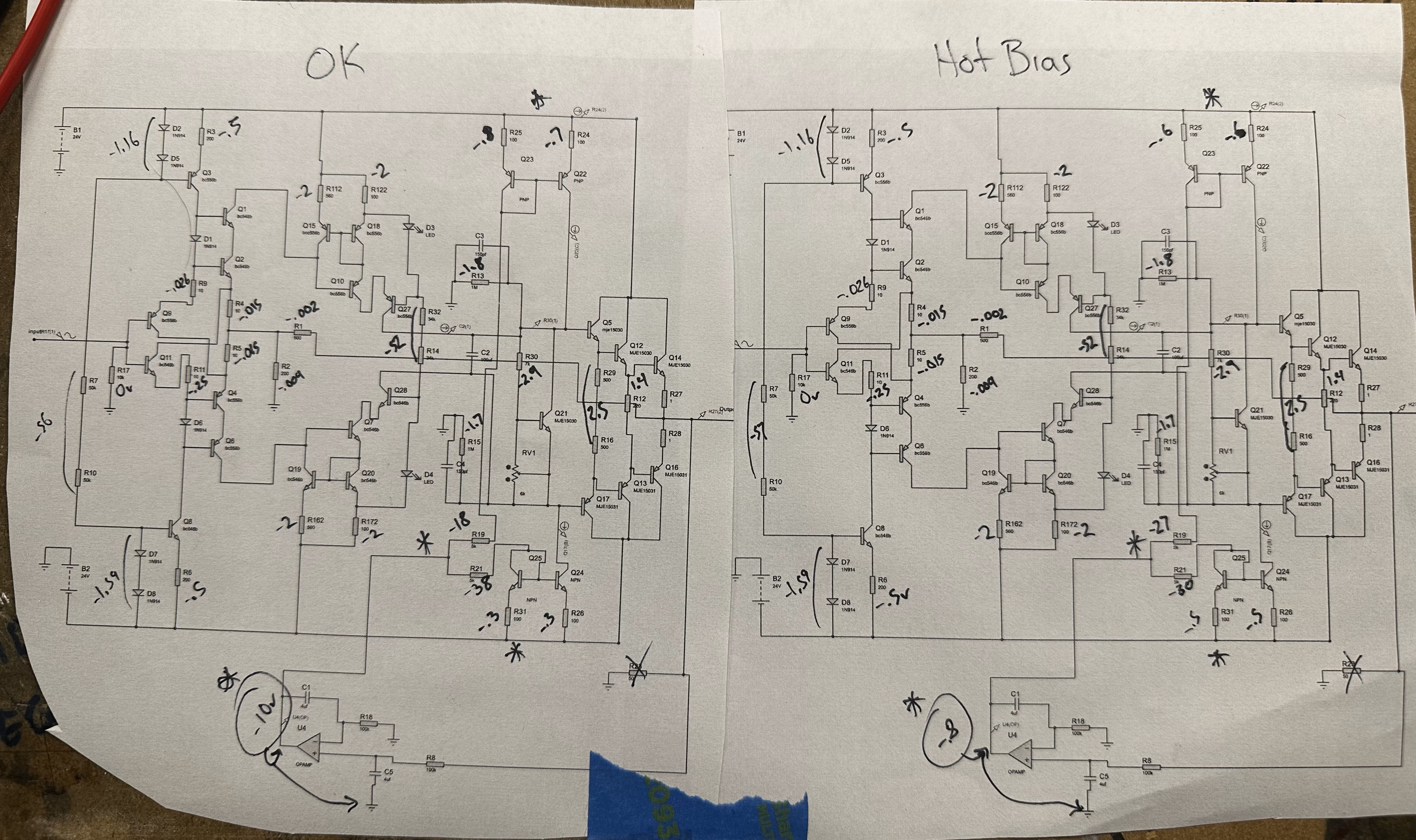
You're completely right, arbitrary to have a negative since I was just measuring drop across the resistors. Dukei recommended measuring drop across resistors vs voltages to ground. I mindlessly added the negatives when I was jotting it down, just a matter of probe position in this case. +10v is the proper voltage after the servo in this case. Thanks for the input, I'll investigate further. Sorry about the size. The resolution is decent, but on a phone or such device it may be tough. The schems I was jotting on were small, tried to keep everything visible. I def often write too small. -
and now for something completely different part 3
Satyrnine replied to kevin gilmore's topic in Do It Yourself
Yes, I've visually verified all parts, and ohmed out each resistor to verify. Checked for cold solder joints, polarity/orientation/etc. N's and P's in right spots. Good eye Pars! Yes, in that pic the two toasted output devices had the screws removed, I've since replaced with new official distributor parts. I do have spares, I'll just replace all the 15030/31's as you suggest. Those are easy as you say, esp with my new Hakko desoldering gun. Inputs to opamp would be the feed/sense from the output right? I should add, I have the amp working in SE mode now, with 120ma bias or so, and it absolutely blows my mind. Unreal power and slam, and the dynamics and detail are just wild. Raw dogging for now without protector board with my LCD-2's and LCD-X's. -
Still haven't been able to test at below 30v, BUT I did find that if I have no CFA boards connected, just the protector board powered, I don't get any hum from headphones. I also built up a second board, and had same symptoms as first, so I'm guessing it doesn't like 30v.
-
and now for something completely different part 3
Satyrnine replied to kevin gilmore's topic in Do It Yourself
I bit the bullet and took measurements of an OK and the "Hot Bias" CFA2 boards. Here is what I found: Test conditions: OK board biased to around 120ma, trimpot in middle-ish position. Hot bias board has trimpot all the way down, which gives about 100ma of bias. Ran from the same GRLV at 30v. Clearly the big difference is the output of the servo is showing 10v on OK board, and only .8v on hot bias board. Servos getting proper voltage on each board. I swapped in a known good chip, no difference. The 5k feeders after servo are showing dif drops between boards too. Can anyone give me some guidance on where to go from here?
-
I ended up using a spare 30v grlv to power the protector board separately. Same transformer. +/- 12v on pins 3/12, still had noise, but it was different sounding this time maybe. Less hf content? Maybe imagination. That mostly (?) rules out that it's somehow injecting the noise back through the grlv and through the cfas, but solidifies that it's happening at the protector board. I think. Suspecting overworking the 12v regs w 30v at this point. Wasn't able to test at lower input voltage because my bench supply isn't bipolar apparently. (I usually do tube stuff, rarely need a bipolar supply until now, hah!) I'm going to go through it and triple check values and get some more detailed readings.
-
I do have a bench supply, will def give that a shot and report back. I'll try it at 12v and 30v to see if there's any difference in behavior.
-
Will have to check the pins tmrw, but fwiw, spec sheet says the regs used max input voltage is 35v, so it is cutting it close. And yes, all unused input pins grounded. On delay is only a few seconds too. I'll triple check everything again asap.
-
and now for something completely different part 3
Satyrnine replied to kevin gilmore's topic in Do It Yourself
I built a protector board up for this. When I connect it to one of the grlv set to 30v (also powering 2x CFA boards), it causes pretty bad high frequency noise on the outputs. Right now in SE mode, grounding negative inputs. I tried grounding two ways: 1) GRLV ground AND cfa output grounds all connected to protector board. (hf noise was present) 2) Only GRLV ground connected to protector, cfa output grounds and protector input ground connected to star ground. (hf noise was worse) When I remove the protector, cfa is dead quiet. I've read these can be used with 30v, but maybe I'm stressing 12v regs too much? -
I built a protector board up for my 30v CFA. When I connect it to a grlv set to 30v (also powering 2x CFA boards), it causes pretty bad high frequency noise. Right now in SE mode, grounding negative inputs. Negative outputs not connected to anything. I tried grounding two ways: 1) GRLV ground AND cfa output grounds all connected to protector board. (hf noise was present) 2) Only GRLV ground connected to protector, cfa output grounds and protector input ground connected to star ground. (hf noise was worse) When I remove the protector, cfa is dead quiet. Thoughts?
-
and now for something completely different part 3
Satyrnine replied to kevin gilmore's topic in Do It Yourself
Was going to go with switchcraft due to being less modular and worried about getting the right pins and all, but these are WAY cheaper than switchcraft too. Do you happen to know the right "pins" I'll need? I'd hate to order the wrong thing, and there are TONS of options with this line. Are locking nuts, plug housing, and everything but pins included with the connectors, or do those need to be sourced separately too? Doesn't seem clear. Datasheets show no accessories. Thanks! Also, does anyone have any guesses on what could be causing the spicy bias on the one board? I'd really hate to resort to shotgunning all the sand to try to find the culprit. I have a decent Hakko desoldering gun, but extensive rework sucks if avoidable. I'm going to go through and measure voltages across each resistor and compare to a working board.