FallenAngel
Returning Member
-
Joined
-
Last visited
Everything posted by FallenAngel
-
I've read that part a couple of times and it confuses me completely. What do you mean "adjust DC offset"? There are no trimpots on this amp. Where does adjustment come in?
-
Yeah, I kind of figured that. Not sure why the "good" board all of a sudden got offset issues though. I personally really hate having to fix boards with major issues so I'll probably rebuilds a new set while salvaging the parts that I could.
-
MAJOR UPDATE! I just realised the "bad" board had the V+ and V- flipped! I wired it correctly and was shocked to find out the following: "Good" board now has almost 1V DC offset "Bad" board now has about 17V DC offset Now I'm quite confused.
-
Inputs are not shorted, nothing connected. No load on putout while testing +9V good, -17V bad pin6 to ground on opamp Not yet measured voltage base/emitter I don't know what the .5v refers to I know it's marked and easy to populate which is why I'm surprised I messed up somewhere. Update: I replaced the 4 SMC transistors, no change.
-
I have not found that to be the case and have a few boards in the garbage to show for it. I tested both board and one works perfectly. Unless I am really blind, a possible scenario, the transistor are correctly placed. It troubled me that redoing the soldering raised the offset a little, making me think something really did burn up before. I'm just uncertain of which to replace. I should have extras around, I think. Any suggestions of where to start? I think smc as those are still on my table. Thanks by the way.
-
Double checked every transistor, all are correctly placed and none get warm. I don't know where to start replacing them and from experience, TO92 are a pain to remove and I've damaged boards before trying. Any suggestions on where to start or which are likeliest to fail?
-
Update: So I just cleaned up the board and redid some solder joints, DC offset is now 2.8V... WTF?
-
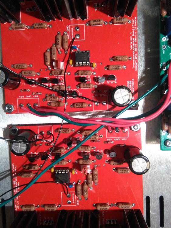
Just completed this amp running from GRLV at +/- 20v, powered it up and see 5mV DC offset on one board and 2.7v on the other Where should I be looking to try to debug it? I measured voltages across a bunch of the resistors and they certainly don't look similar between the two boards. I double checked the output transistors and they look to be installed properly. The resistors also look to be the same on both boards.
-
Thanks my friend. I had thought so but really wanted a clear and direct answer like this. After 15 minutes of setup, I've gotten both boards to about 0v. The second was MUCH harder for some reason but it looks good now.
-
Need more TL;DR than that. Like measure X resistor and adjust TP1 until 0v.
-
What's the TL;DR on settings? 3 trimpots, what should be done with them, measured where and adjusted how? Thanks.
-
Thanks for your posts guys. My question was a leading one in an attempt to have simple and direct parts list for builders that may be very skilled in building equipment but may not have a high level of understanding of schematics or circuits. I was hoping someone would come up with a little table like the following. ((R8 + R7) / R7) x 10 ((1.5 + 1.5) / 1.5) * 10 = 20v ((2.21 + 1.5) / 1.5) * 10 = 24.7v ((3 + 1.5) / 1.5) * 10 = 30v R7 = 1K5 R8 = 1K5 for 20V R8 = 2k21 for 24.7V R8 = 3K for 30v R9 = R7 R10 = R8
-
Thanks Pars and congo5. I checked the bottom of the board and it looks like one part of each secondary gets rectified and fed into the positive and negative rails. I'll just desolder it. Worst case scenario of lifting the PCB trace still has no effect. Glad I double checked, thanks guys. Is there any easy table for output voltage resistor selection? Maybe I'm too used to the other forum.
-
Damn, I already populated all 3 bridges. Should I remove the middle one or just leave it there?
-
Noob style question - how is the latest board transformer wired? I'm using a dual secondary transformer, so I'm assuming I wire the two AC lines and leave the center GND open. Also, what's the 6th input to the side with resistor to ground for used for?
-
I'll be running this amp a little lower voltage than you guys, only at +/-20V, so is there any reason not to use the OP27 in it?
-
The wiring input RCA and XLR wiring I've seen seems to put XLR - and RCA Ground switched and wired through the pot, while connecting XLR + and RCA signal together. Is this really a good way of doing this? Should the RCA ground be sent through the pot for - input? Is there any problem with connecting the outputs of two DACs together like this?
-
-
Looks like MJW21193 is out of stock in Digikey and Mouser Are there alternative components or alternative places to get these parts? EDIT: Grabbed some off eBay.
-
Cool
-
Any thoughts on running this amp off +/- 20V? Also, how sensitive is this amp to power supply quality? As in, is there much difference for this amp to use a simple LM317/LM337 vs Sigma22 or GRLV?
-
Obvious is good. I remember using the TL081 in my Dynalo on +/- 16.4V as originally designed, but this one will be running +/- 20V, so that's important. I got the following transformer VPT36-690, 2x 18V 0.69V, and I assume that'll be more than enough to run this amp using the GRLV psu.
-
-
Thanks! So basically that would mean a GRLV psu would barely need heatsinks to power one of these amps. How large should the heatsinks be on the amp though?
-
Silly question, but what do you mean by "want going to your phones"? How would you calculate that for, lets say 35 ohm HE1000? Applying ohm's law, that's almost 2A with 30V rails (60v) and that can't be right...