Quad
High Rollers
-
Joined
-
Last visited
Everything posted by Quad
-
The charge up is not that noticeably slow, since the RC-time is only 0.47 s (4.7 MOhms x 0.1 microfarad). Before you start the CD, the membranes will be already fully charged if the charge build-up time would be due only to the series resistor in the bias supply. But there is a low impedance (w.r.t. the impedance of the headphone elements, which is about 1000 times larger than that of the final capacitor) in parallel of the output of the bias supply. So it certainly is not just a current source, but much more a voltage source, due to the reservoir capacity of the capacitor. I suppose that the sonic effects are minimal, since the defining factor is the speed of the charge migration on the diaphragm itself. Reason: The time-constant of the diaphragm and the series resistor is only about half a ms, so well in the audio range of the phones. So in order to have low distortion, the series resistance of the diaphragm itself, must be very much larger than 4.7 MOhms. If the charge stays "put" during the slowest mechanical cycles of the diaphragm, the distortion is minimal. If the membrane would be (good) conductive, which is the case on some electrostatic loudspeakers), then an improvement can be made by using a very high value series resistor in the bias supply. I think that the function of the series resistor is primarily a matter of safety. If you touch a connector (or pin) which is at a high potential, a very noticeable and potentially dangerous current can flow through your body. Most likely you touch the (grounded) cabinet of the amp when plugging the connector in or out, which makes up for a good return path for the current. Furthermore, due to the small shock, you might make an uncontrolled movement and hurt yourself or damage something. If, however, there is a high value series resistor, the current is limited to a safe value.
-
Hello bobkatz, Yes, we are talking about the same part of the schematic. But... after the resistor R403 (4.7M) you find the capacitor C417 (0.1uF). After that there is is direct line to the bias-pins on the headphone connectors. So in effect: no series resistor. Just an additional RC-filter stage in the bias supply. The schematic prior to s/n 1000 does not have this capacitor. And thus does indeed have a series resistor in the bias line. Things can easily be corrected for s/n over 1000 by just adding a 4.7M (or an other large value that you happen to have lying around) between the bias wire and the connectors. Best regards, Jac
-
Hello bobkatz, First of all: thank you for the manuals. The notes on old manuals are always worthy of being read. Why invent the wheel twice? So in fact you did implement a kind of balance control after all. Are they sonically of the same quality as the volume control or does that not make a difference? I tend to feel that the sonic differences between volume controls are minimal. One of the main issues to me is very good tracking. The output coupling caps: the listed voltage rating is probably just what Stax had at hand. Which indeed by no means implies a necessary value. I expect that your output caps will sound similar to mine. There is a school of thought that is against too high value capacitors. You could argue by using a largish value, you put a lot of (unnecessary?) dielectric material in the signal path. Which might have its own contribution to sound due to charge being kept in it. Difficult to choose one way of thought of the other. I guess that the proof of the pudding is in the eating anyway. About the 300V diaphragm bias: I am just too chicken to bias all my phones to a value which is much higher than recommended. Since the room I use the phones in, is not humid, I suppose it could not hurt that much. Since my amps can generate more than sufficient output voltages for the phones I use, that alone is not a reason for me to increase the value. My loudspeakers are modified Quad ESL-63 electrostatics, so probably I am used to lower sound pressure levels than most people. It would be nice to be able to learn from Spritzer if, by his knowledge, the higher bias voltage has ever caused harm! It is relative simple to wire the second phone connector as pro bias. 300V is quit low for pro-bias phones, although they will of course work. But at a quite reduced output level. I once planned to do some serious listening tests and decide for my self whether or not the bias voltage actually influences the sheer sound quality. Not talking about SPL. But I have not come to it yet. I do, however equipped my home made amps with a variable bias voltage. I can set the value in steps of approx 2dB from 150V to 1500V. (The steps of 1000, 1200 and 1500V are required for my Jecklin phones.) Higher sensitivity indeed does mean more headroom in the amp, which sometimes is a major benefit. Depends on the amp of course. Your action of making a feed-trough connection is certainly useful. I did the same on my own amps. The bias series resistor is definitely not part of all Stax amps. F.e. see the service manual of the SRA-12S for s/n over1001. C417 is directly across the bias output, and they did not put a series resistor in that line. Concerning EMI and RFI: for high frequencies the current idea (in contrast to early thoughts) is indeed to groud as much as possible. Connect all connectors and screenings directly to ground. For LF however, induction of flux from the mains or a nearby mains transformer quite easily induces a 50/60/100/120 Hz hum component in a ground circuit. For European versions of audio equipment you see all kind of ceramic capacitors connected across input and output connectors. Just to be able to conform with the immunity regulations. Usually ceramics do not a lot of good for the sound. The induction of mains hum was a serious problem for Stax with the SRA-14S. The prototypes had a built-in mains transformer, but since the circuitry was too sensitive to induced hum, they decided for the final production series to use an outboard transformer. My own amps have there input jacks isolated, but my main ground connection is somewhere in between the connectors. Sometimes it is required to make an additional ground connection at a different location. Thinking things through combined with some trial and error work, will give a solution. The are different schools of thought about paralleling capacitors, as you indicate. Audio Research for one, used to have all kind of paralleling in the deep past, but now often choose to have just the supply electrolytic. Since the power supply actually is in series with the output, a very good quality supply will not go amiss. Which does not at all necessarily means electronically regulated... I tried several power supply concepts for my DB Systems DB-1 pre-amp and could detect not a major audible difference. So I restored it to the original concept. My measurements do not confirm this outcome. But I still feel that a good MKP does not do any harm Thanks again for making the manuals available, and have a lot of fun listening to your Stax equipment! Best wishes, Jac
-
Hello bobkatz, Good to see that more SRA-12S amps are still in use. You are absolutely right about the quality of the intermediate-stage amp and the phono board. Normally indeed there is no need for the additional gain, and it causes audible noise as well. Part of the cause of the noise is the high impedance of the volume control (250k if I remember well). You did the right thing by choosing a much lower value. Personally I feel that a balance control is indispensable. A lot of recordings are off balance, and my ears have some damage that needs correcting as well. My volume control happened to have sufficiently good tracking, so I left it in place. More so, because I wanted to keep the balance control also. I tried to keep my SRA-12S as original as possible, so I left all boards functioning and restored them all. In practise I only use the direct input (via the vol/bal controls) to the output amps. I think that the 2 uF is way over the top. The headphone represents primarily a capacitor in the order of 100 pF. So you get a capacitive divider of the headphone and the coupling cap. The (DC) charging time for the 2uF is also a bit long, since the charging resistor is 10 MegOhms. I also feel that 400 VDC is on the low side. At most, 650 V could be across the capacitor. During normal operation, the DC voltage across the coupling capacitor should not exceed much over 350V. I do not know the voltage rating of the original output coupling capacitors, since they were already replaced by the previous owner (or most likely by his repair center for that). The capacitors I used are rated at 2000V, but that is just because I had several of them already. And they, more or less, fitted on the pcb. If you are in need of them, I can always mail you 4 pcs. About the biasing the output stage: At the time I did not have the equipment to measure distortion of a balanced system at a few hundred volts of audio voltage. So I just adjusted for max output swing (as observed on an oscilloscope). By the way, this setting corresponds closely with the prescribed value by Stax. (At the time I only measured the distortion of one half section of the output, since you could treat that as non-floating. The distortion was quite large, but is virtually canceled out by using both output halves.) Since then I have made an extention to my HP 339A distortion analyser, in order to be able to measure the output of this kind of circuitry. If proved good value during the development of 2 amplifiers of (partly) my own design. If I come to it, I will do some measurements on the SRA-12S. More current might not necessarily "bias them better", since each transistor is a single-ended circuit with just a resistor as collector loading. For a momentary output voltage towards the (positive) supply rail, the source impedance (to the load) is the collector resistor. If you set up for a higher collector voltage, the collector current actually drops. Because the collector current is (supply voltage minus collector voltage) divided by collector resistor. Or to put it simple: Just the voltage over the collector resistor divided by that resistor. So setting a higher collector voltage actually drops the voltage over the resistor, hence lower current. Just try some different settings, and most likely you will find that it makes no audible difference. The diaphragm biasing voltage for the phones was originally 200 VDC, and 230 VDC for later types. In fact it was 200 VDC at the time of the SRA-12S. But most normal-bias phones, if not all, could stand a higher voltage. I added a "pro" biasing output as well, and I put that at the recommended value of 580 VDC. Again, most pro-bias phones would be able to handle a substantially higher value. The SR-007 f.e. certainly would. It also depends a bit on the air humidity, how high you can go. And the risk you want to take. Once a flash-over has happened, I suppose that there is conductive material (carbon) at that position, and the element will never be as it was before. For my ears there was not much difference in sound (quality), for relative small variations of the diaphragm bias voltage. What does change, however, is the efficiency (or sensitivity as you could call it equally correct) of the phones. The bias voltage is just there to put, via a large series resistor, charge on the diaphragm. The more charge, the more sensitive. All that to a certain upper limit of course. The (very audible) higher output (with the same input voltage) gives the impression of higher quality, but in reality it makes very little (if any) difference, if you carefully adjust (reduce) the sound output to the original level. It just gives mote "total" amplification, but that has no relation with quality per se. Just do add a high value series resistor to the headphone connector, if it is not yet in your version. It is suppose to supply current, not voltage. The do or don't of grounding stays an interesting subject. If it induces a hum component, it obviously is not the right way to do it. If it doesn't, it is to your personal opinion whether you want to ground it or not. The SRA-14S for example is sensitive to grounding problems of the internal wiring. I usually keep the input connectors floating, but for the utmost in EMC immunity, grounding might be the better option. But the circuitry and component (cable) quality should always be such that it does not make a difference in the real world. The +/- 15V supply is fine at +15.2 and -14.7. There really is no need to replace the circuitry. I just took care of good electrolytic capacitors and added a polypropylene across each supply. Integrated circuits sometimes are better than discrete, but not necessarily so. I briefly tried a setup with IC-regulators (just to be on the safe side, audio-wise), but was not able to detect any difference. Quite in contrast with popular belief, I feel that the SRA-12S is a very good sounding amplifier!! And yes, I would very much like to have a high resolution scan (300, or better 400 or 600 dpi) of the user manual! I will send you a PM with my e-mail address. Thank you in advance for taking the trouble. I am looking forward to it. Best wishes, Jac
-
Hi htless, Some more detailed ones would be helpful. Would it also be possible to get some high resolution pics of the EMM-1 -module? top and bottom and some at an angle to see the components and mechanical construction better? Maybe some day I will try to rebuild it..... if I can get enough info on it, that is. And I will try to make a JB-1 (line level input) module. Just to have a nice view at the back of the SRA-14S, and see the appropriate led light up on at the front panel..... Thanks. best wishes
-
Hi Birgir, Yes, somehow I feel that you are (again) right. Onto the other Stax equipment the usual text is screenprinted. Nothing on this one however... Thanks again. Hello htless, Thanks. That would be appreciated. And yes I had found this japanese site some time ago. No detailed pics of the SRA-14S. They also have a section with brochures/user manuals. The links to the brochure of the SRA-14S (2 pages) do not work.... Maybe someone has an original brochure of the SRA-14S. A copy or high-Q scan would not go amiss I would not even say no to an original one Let's hope the service manual and one or two of the equalizer-modules come my way someday. Thanks for your contributions.
-
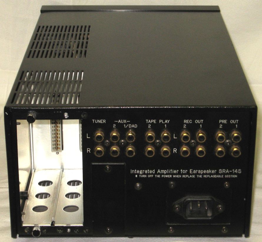
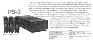
Hello htless, Thank you for your additional information and your photos ! All very interesting stuff. The PS-3 power is made specifically to use as a phono pre-amp unit with one of the available SRA-14S cartridge modules as a head-amp for one of the SRM-amplifiers. This way you could create a (I presume very high quality) phono input on a line-only amplifier. Probably a good way for Stax to sell the separate modules. The PS-3 cost about a quarter of a complete SRA-14S in Japan. All pictures I have seen so far from an SRA-14S are with an outboard dedicated power supply unit. Mine could very well be an early (or late??) model model for other uses than the consumer market or perhaps it is a kind of pre-series or prototype. Never seen one like this, so without more information it remains just guessing. I would be very interested however in some good resolution internal photo's both of one of your your SRA-14S and of the SRA-14S power supply unit (or of both, if there are any (small) differences). That way I can ascertain that the built-in power supply is made of exactly the same components, which I guess it is. And some (large) electrolytics have been replaced in my unit, so it would be nice to see their original value. It would also be nice to see how things are arranged internally in the SRA-14S when the power supply is separate. Thanks again! Some day I hope to get hold of some service info on the SRA-14S.... Best wishes.
-
Thanx! Yes I am very happy to have the SRA-14S. I always wanted an SRA-12S and an SRA-14S. Well, now I have both of them! Let's hope someone can help me to a service manual for it. Then I can restore it to original glory....
-
Yes, that is also what I have always assumed. Thanks for the information on the switches. No s/n, but the sticker or plate could have been removed someday. Even at a prototype you would expect some indication. Since I never saw pictures of an SRA-14S with internal power supply, there is very little to compare to. There is no text "Serial No._____" on the back, like on the "standard" version. Although I knew on beforehand that there was no s/n on it, I still bought it. Always wanted to have an SRA-12S and an SRA-14S..... Well, I have both now As soon (or not soon....) as I have more technical info I could start with the restauration process. By the way, the internal mains wiring looks original, so indeed it could very well be a kind of protoype. There should be some more around, but maybe only in Japan. The 2 little "handle-bars" on the bottom side of the front panel are missing. It is not to disturbing though. The seller will try to bring me in contact with the previous owner of whom he seems to have bought it about 3 years ago on Ebay. With some luck it might be possible to follow part of the history back. I find that always nice to know.
-
Hi padam, Thanks, our posts have crossed each other. I already found the user manual some time ago. Nice to have, since usually it is also difficult to get hold of. All the best.
-
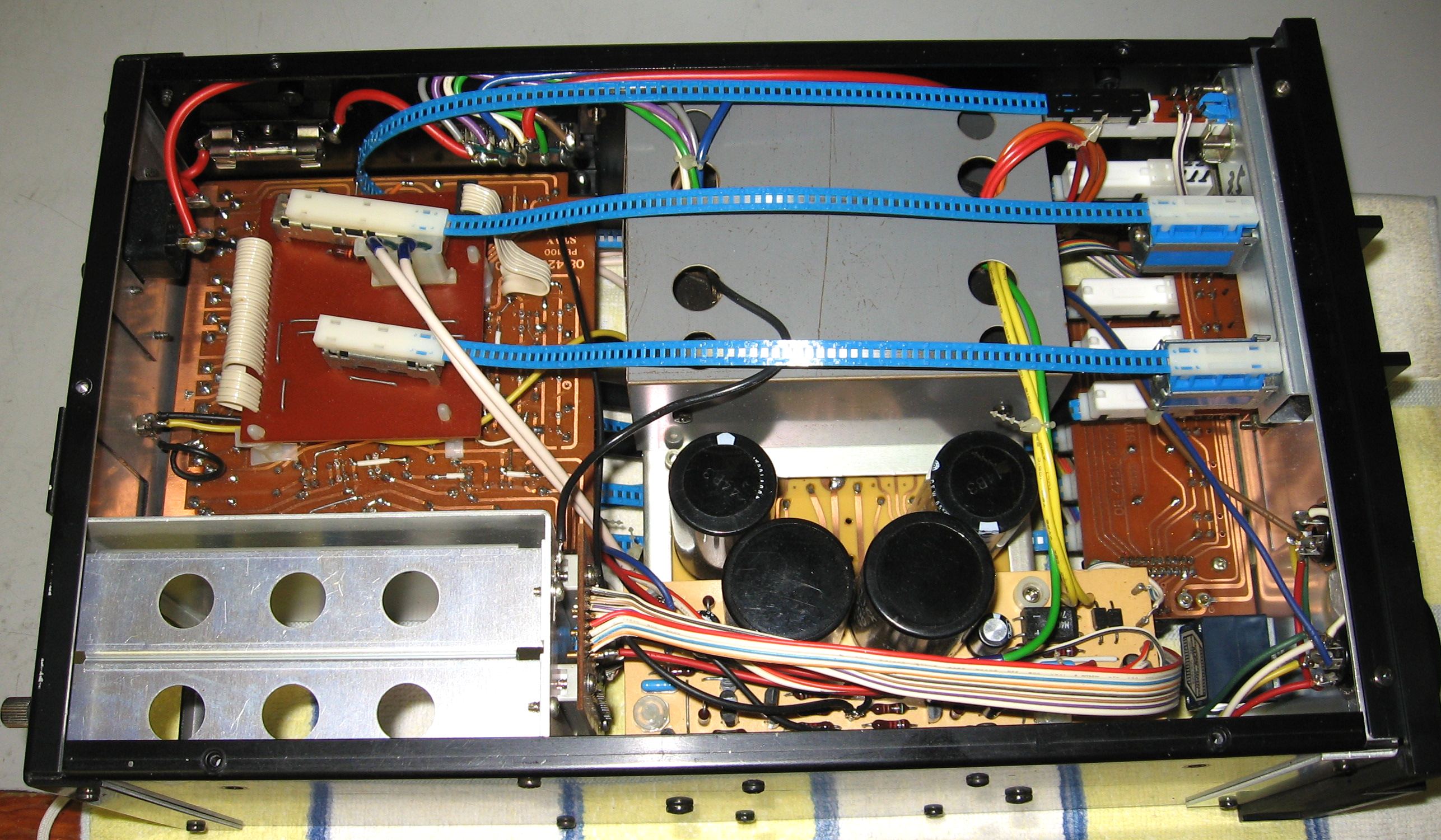
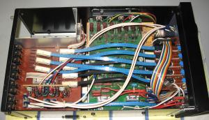
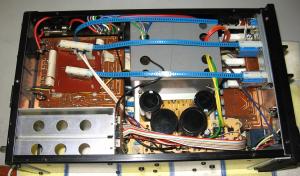
Hi Spritzer, Here they come. The IS amplifier is on a separate board, with somewhat lower gain than the SRA-12S. That is a good thing. Less noise also. The gain without the IS is sufficient though (as is the case with the SRA-12S, i.e. 60dB), and then there is no audible noise at all. All switches are connected by flat bowden cables to the front. Not easy to service this way. Do you happen to know any reports about bad switches? It is not (yet) clear to me why there are so many cut traces and added bridge/jumper wires on one of the switch-boards. (Maybe on the other switch-board too, I have not yet looked at the copper side) Also one of the HV electrolytic capacitors is missing, but the missing one has been paralleled with the one next to it. It has a very small hum which strangely enough disappears when I engage the IS.... So I suspect it is caused by the changed boards. The tracks have been removed very neatly, so it is barely visible where the original traces have been. With a circuit diagram and a pcb drawing things would be a lot easier to follow. All I have so far is the instruction (= user) manual. Nice to have though. Well, so far I am happy with my SRA-14S, and I hope that a service manual and some input modules will turn up somewhere. Then there will be a full restauration. For now I will leave the SRA-14S as it is. Best wishes.
-
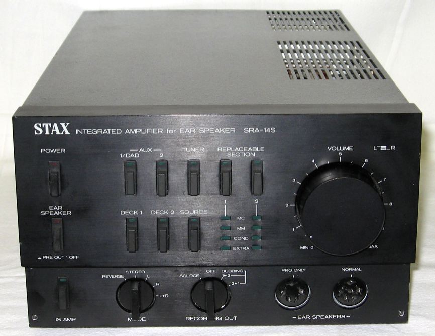
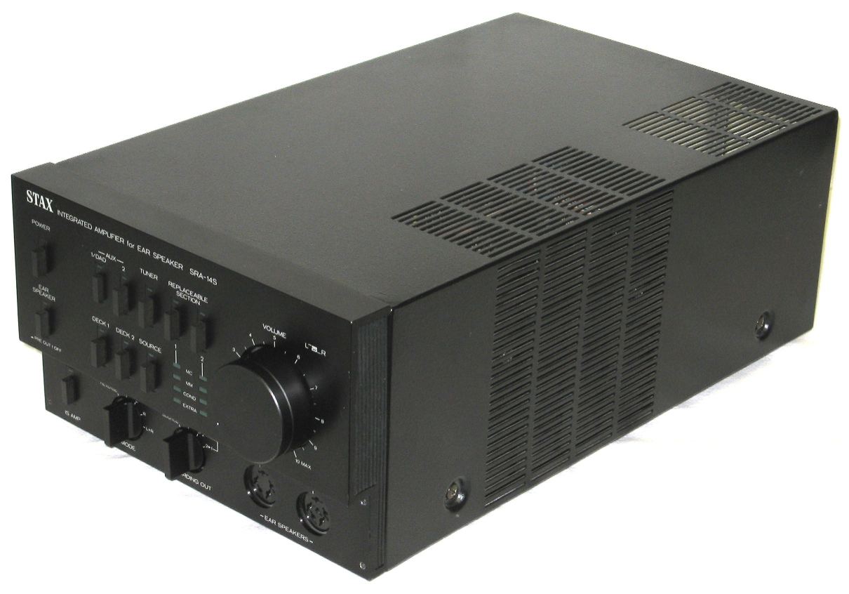
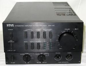
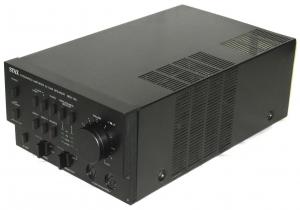
Finally I was able to acquire an SRA-14S and it has arrived now! No phono equalizer modules however. A previous owner had been cutting copper tracks on the input/switching pcb and added a lot of wires (in different places than the cut traces). Neatly done, but still.... Maybe he had some problem with the switches? So restauration will be a major undertaking without documentation. Can anyone help me with the service manual and/or schematic diagrams? That would be highly appreciated. Paper copy or electronic, everything is welcome. The headphone amp looks at first glance like the circuitry of the SRM-1 (of which I also have no service manual), but the power supply looks a lot better. A vastly larger transformer of much better quality than usual for Stax. So it may even sound a bit better. I switched it on briefly and it sounds very promising. This is the version which has the power supply built-in. Previously I did not know that this existed, but it turns out to be completely original! It uses the same components as otherwise in the external power unit. Much more convenient this way! The transformer has a specially wound core, so the stray field could be low enough for this. If there is any interest, I can post some pictures of the innards. Thanks in advance for any help with the service manual!

-
Congratulations Birgir !! I am jealous already...... This is definitely THE amp we all would like to have. No chanche of building one without the schematics I am afraid.... Looking forward to seeing a detailed comparison with the other famous amps. Enjoy it ! Quad
-
Thanks for your help Birgir ! (Is there anything at all that you do not know about Stax?) Best wishes.
-
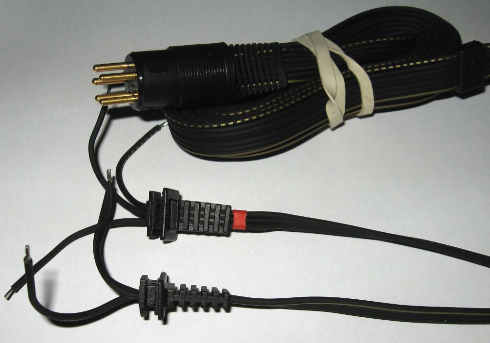
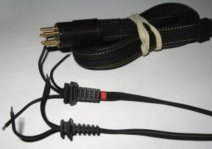
Hi all, Recently I acquired a replacement Stax cable. Could anyone determine for which type(s) ear speaker it is intended? (Just curious to know it....) Some characteristics (see picture of the cable): * the continuous and dotted lines are gold coloured * the cable is matt black * the length from the tip of the connector pins to the feedthrough at the speaker side is approx 2.39 m * the overall width of the cable is 13 mm * the connector is a 5-pin gold plated type I might use it for a SRX-mkIII (or mkII with torn membranes I have to repair) after a planned conversion to a pro version. Or even to improve my Jecklin Float. The capacity of the stock cable of a Float is so much higher than the Stax cable, causing an unacceptable and unnecessary high load to the amplifier. But than I have to get a high bias voltage to the Stax connector (1200 or 1500 V for the Floats, depending on which type it is). And I might forget to set it back to the 580V Stax voltage before I connect my dear Stax.... Not a good idea at all, when I think about it; I'll stick to the Hirschmann connector for the Float and find an other type of lower capacity cable for the Float without having to cut off a precious Stax connector Thanks!
-
You are welcome, Deadneddz. The BH will most likely sound superior to the T1. I have not been able to audit a BH, but the circuitry looks sound to me. The high current in the tube output circuit will enable the BH to supply a lot more current at high frequencies. And if the output impedance is much lower than that of the T1 (which I expect it to be, but I never did calculations on it), the sound certainly will improve overall. If the output (source) impedance is low, the unwanted currents in the cable capacitance have far less influence on the amplifier. Since a major part of the headphone+cable capacitance is caused by the cable, this could be a determining factor. The capacitance of the cable has some unwanted characteristics (f.i. the loss factor) and gives unwanted output currents in the amplifier. And these currents are larger than the wanted currents in the headphone element itself! So, al in all, I would expect to have a better sound quality from the BH (or any other capable amplifier!) than from the T1. Not that the T1 is bad; quite the contrary. But it has its limitations. Let us know your findings, if you will ! I always learn from experiences from others. That make me attentive of things I might not have payed attention to if I was to find out all by myself. Good luck and enjoy the Signature.
-
Hi, I prefer the SR-Lambda Signature way beyond the SR-404. I was able to use both and decided I preferred the Lambda Signature much over the SR-404. I let the SR-404 go and still have the Signature. Especially the very sharp s-sounds of the SR-404 annoyed me. It depends a but on your choice of music, but since I enjoy female jazz vocals, I could not live with the 404. Some experimenting showed that some damping/filtering can give a very large improvement. To get the idea: just position some thin fabric of your choice between your ear and the phones. You hear the change immediately. Unfortunately the coin has two sides: you trade in some spaciality. The Lambda misses the very sharp intonation, but is not as neutral in that as the SRX-mkIII for example. To my opinion the damping of electrostatic phones is a very critical item. F.e. my Jecklin Float improved a lot by adding a piece of fabric on the outside of the electrostatic cell. Both treble and bass are more linear. An easily achieved improvement can be the use of very good tubes in the T1. If it still has the stock ones, replace them by NOS good ones. In my SRM-006t the change in quality was larger than I expected it to be. The circuitry of the SRM-T1, T1S, 006t and 006tII is almost identical, so I expect that the T1 would certainly benefit as much from top quality tubes.
-
The capacitor is across the bias (to ground) and not in series with the bias line, so I see no problem. It will filter a little bit of the mains ripple, due to the resistor before the capacitor, but not much at this value. But the current consumption is very low, so the cap will stay charged and there will be very little ripple anyway. As far as I know the following Staxes have a parallel output capacitor of 0.01uF (and no series resistor after that!): * SRD-7 * SRD-7 mkII * SRM-Xh * SRM-X pro * later versions of the SRA-12S * your new pcb There may be other types as well. The series resistor does not really make a constant charge circuit, since the value (4.7 or 5 MOhm) is way too low for the capacitance of the phones (say less than 150 pF). The time constant is about 0.75 ms, so this is not active anymore below several hunderd Hz. Thanks for your input on desirability of the series resistor. I fully agree that it is beneficial.
-
Hi Birgir, I am missing the input resistors (4R7?). I suppose they have an equalization function as well as presenting a better load to the connected amplifier and give some addition protection to the phones (thermistors) and your ears And why not add a normal bias tap as well? I have an SRD-7 (normal bias). If it helps for you to know how the transformer wires are connected in there, I can open it and have a look for you. These adapters have an output capacitor across the bias output. Some amplifiers have that as well, but all later ones have a series resistor to the output. That gives some protection against short-circuits (burns in the membrane if the membrane touches a stator?) and makes it safer to touch. In my SRA-12S, I added a capacitor across the output first, but later decided against it and added a series resistor (4M7) as well. What is your opinion about this?
-
Thanks Birgir, If the construction is different, it certainly would go a long way towards explaining the claimed sonic differences between SR-202 and SR-303 / SR-404. And puts some light on the opinion that the 202 is, soundwise, more closely related to some of the Lambdas than to the 303-404.
-
Thank you padam, One of them indeed is the post I had read sometime, but was unable to find back. It all helps to get a better picture of the 202-303-404 relationship and preferences. Quad
-
Thank you padam. Would you happen to know what the precise difference w.r.t. the drivers is? I too am a bit dissapointed by the coloration of the SR-404 (compared with my SRX-mkIII) and by the pronounced s-sounds (most noticeable in female vocals). Thanks. best wishes, Quad
-
Could anyone point out the precise differences between the Stax SR-202 and the SR-303? I understand that the difference between the '303 and '404 is only the cable, but I was wondering what about the '202? I have read something about it somewhere (how's that for being vague.. . Maybe in the Stax thread), but I am unable to trace it back. Thanks for the help!
-
Hello Mark, Thank you for your comment on my write-up. I am glad to see that there are some more 12's still in existence . Yes, there is some noise on the line inputs. When I use the SRA-12S with my SRX-mkIII, and use a cd-player at an aux input, the amplification is sufficient without the interstage (I.S.) amplifier. Just push the most right button. Then the noise is gone. The amplification in that case is the same as of the current Stax amplifiers: 60dB, or 1000x. (Some recent ones are 54dB, or 500x, to have the complete information.) It certainly pays off to use the best quality capacitors you can find. No need to use exotic types, though. A small investment in good quality polypropylenes, however, is justified. And, what most designers seem to forget, the power supply in fact is more or less in series with the audio signal circuit. So not only the amps themselves should be good, but the supplies as well. A parallel polypropylene capacitor across the 650V certainly does a lot of good. I used 220nF, just because I had one. But I guess that 100nF will be equally well. And if you have an old type SRA-12S, it will still have 1uF electrolytics on the small power supply board. Replace them by 1uF (50V or higher) film capacitors. Check all electrolytics, and when in doubt, replace them. Do use good quality types. in my '12 I only had to replace the 1uF and a 220uF-6.3V one. The others were in absolute remarkable condition, and measured (at capacity and loss factor at 1 kHz) better than many new samples. I added 2 capacitors 1000uF-35V for the + and - 15V. The '12 I have "only" has 1000uF originally, and the later versions already have 2200uF. And I put a 100nF MKP across the 24V. The output capacitors had been replaced by the previous owner (I guess that this was done by the Dutch importer). The original value is 4.7nF. A larger value does not hurt, and I have some 10 nF 2000V Philips MKP capacitors, so I replaced each output capacitor by one of these. So, 4 in total. In the picture you can see them on the output boards: the yellow blocks. Philips has made some very good components. Note that not all of the yellow blocks are of the same dielectric (and thus audio quality...). The large resistors and power transistors on the output boards get quite hot, indeed. The transistors dissipate about 2W each, and the resistors 2.4W each. Take care in properly adjusting the mains setting and the output amplifiers (balance and voltage: the collectors of the transistros should have the same voltage, and the voltage between collector and ground should be between 280 and 300 VDC). The #2 pre-outs are switched with the middle one of the three switches ("output"). Pre-out #1 is always on, pre-out #2 is off if you use the phones. So that appears to be correct in your case! Finally check the bias voltage. If you do not have a meter with a very high input resistance, just measure before the 4.7M resistor. The circuit of the amplifier looks relatively simple, but it has quite some interesting ingenuities embedded. Absolutely first class for the period and certainly, with some attention, still very very good indeed today. You don't happen to have a user's manual, do you? If so, I would be delighted to have a (high quality) scan of it. Succes with the restauration of this excellent piece of engineering! If you have any remaining uncertainties, do not hesitate to ask. Best wishes.
-
MachMat sold me crappy capacitors once. I sent them back, but he did not reimburse me fully. Not recommended by me.....