

arnaud
-
Posts
281 -
Joined
-
Last visited
-
Days Won
1
Content Type
Profiles
Forums
Events
Posts posted by arnaud
-
-
Agreed. The number of people bitching about the price is overwhelming, and some are even treating it as a personal affront it seems like. If you don't want to pay that much don't buy it, it's as simple as that.
I think the concerns raised by some about the pricing are fair (this time). I like to think that something is not being priced up simply because it can. The 009 is way too expensive but, naively maybe, I like to think it's simply a by-product of intricate manufacturing process / large R&D investment. As of now, there's been no objective justification of the large cost increase. Does a new trace for the coil justify it? I'd like to hear why. Maybe they're going to tighten the tolerance on driver pairing, driving up the rejection rate?
In the end, it all can be just BS justification but, at least, it doesn't leave a taste of being "taken for a ride". It probably sounds like a 2kUSD headphone and I understand the concept of supply and demand, yet it doesn't mean I just want to accept it without raising an eyebrow. Without this kind of healthy skepticism on the pricing, the headphone audio world will become just like the traditional speaker audio industry with unreal escalation of prices vs. actual performance jump.
-
Oh, and one other thing I just realized is that we can actually see the influence of acoustic resonances in the earcups and the effective damping by looking at the isolation graph. In particular, I believe the negative sound isolation (so an amplification of the signal when wearing the headphone) is a sign of a resonance with peak amplitude at the microphone location. Interestingly, the mk2.5 has very peculiar isolation performance which probably gives away the frequency at which the vent is tuned. I am quite interested in trying a few things out through simulation now

Edit: humm, why does the sr003 show the exact same negative noise isolation as the other headphones? Isn't this result just an SPL difference without/with the headphone in place averaged over a few speaker locations in the test cell? Or maybe the FRF is also going through this "independent of direction" equalization hence I am just seeing the shape of that filter? It should cancel out in the SPL difference though, humm...
PPS: The isolation curve is SPL_withheadphone - SPL_without ? I am confused because normally, the term noise reduction implies "reduction of SPL due to the device" hence a positive value means there is attenuation. But your graphs are plotted the other way around no? (-10dB means that SPL went down by 10dB)

-
Tyll, this is EXCELLENT! Your measurements are really of amazing consistency (the 2 SR009). I was shocked to see the differences between the Omega2 Mk1 and 2.5. Seeing this and comparing to the 009, I think my pair (a late Mk2 e.g. SZ2 series) is closer to the mk2.5 than mk1. The mid bass hump / lack of infra-bass and warm signature with just a treble spike makes a lot of sense as these are basically the things I hear as large improvements out of the 009. Oppositely, Birgir is not noticing such drastic improvement going from his Omega 2 to the 009 and I guess it's because he worked out how to get Omega 2 to sound the best (using mk1 drivers, closing the vent, adjusting the ear pad depth and so forth...).
-
Here are my current amazon preorders:
Wilco - The Whole Love (9/27)
96/24 on HD Tracks!
-
I'm a bit cautious when getting modern remasters of classic records. Most of the time they end up being louder and with a narrow dynamic range. Maybe I'm wrong. I sure hope so.
Incidentally, I was checking this while listening to the wall and while most of my rock albums don't often exceed 25dB of dynamics range, there are plenty of moments on this one in the -40 to -60dB range. I no longer have the original CD version to compare, but I doubt very much any dynamic compression was applied to this remaster, it actually very much sounds like an "old school" mastering job with plenty of dynamics. Having said that, it is maximizing redbook dynamic range with peak levels near 0dB.
-
I haven't followed the re-release of recent years so I literally jumped of my seat when I listened to The Wall (from the discovery box) tonight, after a 10+ year hiatus. Between the remaster and the upgrade in my listening system, I'd say I was rather pleasantly surprised by the sound. It's simply awesome sounding through the 009!
-
Tyll: ok, looking at the frf closely, it would seem like the 007 you tested was tuned at 50Hz while the 009 is tuned at 65Hz. Since there can't be any acoustic or other mechanical resonance, it must be it!
Birgir: i would start with 100dB. I see it translates to 100Vrms on the brochure. Does that mean 280V peak from stator to stator?
-
Hi Wachara,
I tried to PM you at HF for some basic info on Stax electrodes but maybe you don't check there so often.
I am after some ball park values to help with a simulation of acoustic performance of the sr009. The things I am looking for in regards to Stax headphones:
- Typical tensioning on Stax drivers
- Typical first resonance frequency
- Typical stator diaphragm spacing
- Typical polarization potential of the membrane (I guess it's affect by the coating?)
Any info you can share would be much appreciated!
cheers,
arnaud
- Typical tensioning on Stax drivers
-
Reading something on HF? You must be mad...

While the data we have are just small pieces of a much larger picture we can extrapolate from it and get somewhat plausible results. There is also a way to calculate the force but my brain is just too fried to even contemplate thinking about it...
Hi Birgir, I got some hints from Bob (Robbo1802) and also referred to Headcase's intro but it's not quite meshing well with the model. Do you have any idea of the typical first resonance frequency of the diaphragm, is it in the range of 50Hz or much higher / lower?
For the estat force, do you have any idea of the stator to stator voltage under normal operating conditions and polarizing potential on the diaphragm?
-
If the diaphragm was loose-ish then I could see this to be true but once we factor in just how tightly stretched the Omega diaphragms are and the relatively weak force at hand here then any large scale excursion becomes improbable IMHO. Best way to determine this would be via distortion analysis because once you get any large scale excursion in a push-pull driver then the distortion rises quickly.
I see... I would not call the diaphragm in my current simulation loose though: the effective Young's Modulus is something like 5 orders of magnitude higher than the default Nylon value, 2 orders of magnitude higher than steel. If anything, the model is way stiffer than real life so actually figures are north of what I have shown. But really, without further test data (electrical impedance) or possibly SPL test on the driver out of the assembly, I can't be sure of anything...
BTW, the force I am using a 1e-6 N uniformly distributed over the whole surface. Is there a quick / rough way to estimate the estat force under normal operation from the specs? I meant to have this discussion in the simulation thread I created on the other site but did not manage to drag your feet there

-
Given that the diaphragm doesn't move at all (it just vibrates) then I doubt any run it will add to the impact.
Birgir, I have been wondering for some time now what kind of displacement values were generated for estats. Even though my simulations of the SR009 are still very very preliminary, I am showing below the RMS displacement at the center of the diaphragm in order to generate about 100dB SPL at the base of the earcup. I need to see how this varies with changing the diaphragm properties (since my properties are bogus atm) and earcup cavity absorption but it should not vary by orders of magnitude. I will redo a simulation with finer frequency resolution so we can see the displacements from 20Hz. I suspect it is not that negligible in light of the 0.5mm spacer thickness...
RMS displacement at center of diaphragm:

SPL at base of earcup:
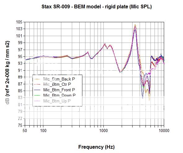
(not to scale) animation of the response at 50Hz: http://www.youtube.com/watch?v=CrriaT_tQuk
-
Marv, I agree that thd and such non-linearity monitoring graphs have more likely to show the differences. Actually, having compared te stock 323s and 727a amps driving the 009, I really thought I could hear significant differences in the lower register. It was with unfamiliar source and material, at a noisy store, so I guess the differences were not subtle...
-
Just a feeling atm but I doubt you'll see drastic changes on the SPL response, simply because differences between amps are of the order of nuances which would fall within repeatability accuracy of the tests... Not saying you can't hear it, it's just that our hearing is so much more accute than visible differences between 2 graphs. At least for SPL / impulse / step response graphs...
-
You, sir, are insane .... insanely cool! Great stuff!
Tyll, I posted some new results in the simulation thread over at HF ( http://www.head-fi.org/t/572968/modeling-headphone-s-acoustic-performance#post_7782482 ) with some comparison against your test data. Not quite there yet with the model it seems
-
Spritzer, how about the modded 727 (I know I'm cheap), you still got one around no?
-
Interesting point on the volume. I think I'm at around 65dB in average so not what you'd call loud. I crank it up at times and crank it down too with the SR009 playing edgy recordings.
-
I'll start with the first point for now: there is no such thing as energy storage in a thin airgap. Energy is stored in modes, therre are no modes through the thickness... What it does though is mass load the diaphragm and add damping if vsicous effects are significant (e.g thin layer, small holes in the stator...). I am in the process of looking into this for simulation model.
In summary, this stator to stator spacing (and stator perforation ratio) is part of estat design and has many function (controls the force, damping...) but it's not the source of estat advantage over different technology
-
Do you know anyone who has tamed the treble peril of these?
Try a search for HD800 mods on HF, you should see at least 3 different kinds, all revolving around adding some sound absorptive material (thin lining) inside the earcup (over the frame part, not the acoustic mesh). I even did a computer simulation back then to see how much attenuation of the treble I would get and the test data I got recently (credit to Purrin) showed it was bang on (2-3dB in the highs which is about just what the HD800 needs to sound natural to my ears). Obviously source and amp pairing needs to be thought about as well but this type of modification is much more effective (and possibly intrusive if you go overboard) than any amp rolling.
Having said that, I am in no way returning to an HD800 from my 009 experience, be it modded or not... Get ready to take the plunge

-
Tyll, very much looking forward to your review! Same for the other experienced people here actually, Voltron you got a few comparisons to make
-
...it was said by people (who seemed to know) that the major problems Stax was having was low yield and the difficulty of matching the drivers well enough for a stereo pair.
...
arnaud
Ohhh, I didn't know you did that sort of work (he says, figuratively inching away from the keyboard - hows the medication working out
 - sorry couldn't resist).
Regards,
Bob
Hi Bob, there is an issue of low yield on the 009, but I reckon it's for the stator, not the diaphragm.
Sorry, I didn't figure out the last part of your post, you'll have to be less subtle for me to get it
-
10kHz @ 50% humidity attenuates 4dB over 30 meters, while 100Hz has essentially none; over 3 meters which is a more realistic listening room distance the difference is inconsiquential. So there is high frequency roll-off, but it's quite a small number. My understanding is that most of the percieved HF roll-off in listening rooms is from higher absorption of the highs in furnature or carpet in the first reflection and reverberant sound.
I guess Ed was referring to natural attenuation of HF with distance in a 100+ m concert hall in case the mics used for the recording are placed near the orchestra pit. Nevertheless, I agree with you the effective absorption in treated concert halls has much more to do with the walls / audience than actual attenuation in the air...
It's likely that variations in manufacture are smaller than the errors of repeatability. It's also pretty hard to get say 10 samples of the same headphone for a study of manufacture variences. Changes in earpad wear might indeed be big enough to measure; it's my experience that ear pads make a big difference.
This is an interesting topic and it's actually the foundation for the simulation work I do most days (Statistical Energy Analysis). Fundamentally, any systems that's made of a buildup of parts, each with its own complicated dynamics is bound to have large variability across a population of nominally identical samples WHEN you get into so called "high frequency regime" (e.g. where parts or all of the system has many modes, kind of like the diaphragm pictures in my 009 model).
It is so bad that, even if you were to crunch numbers with a supercomputer and try to model the response of the system with so-called deterministic tools (like the FEM simulations I showed in this thread) where each part is assumed perfect shape / perfectly connected to the next and what not, you won't be able to match the response of the actual system within even 20dB accuracy.... Simply because just measuring the system 100 times will give you 100 different curves with such kind of 40dB spread across the ensemble at any given frequency. The source of this is basically the very high sensitivity of the system to small perturbations (temperature, small mass, small change in shape, you name it) as the frequency increase (each local mode changes ever so slightly to make the transmission of energy vary from the previous time).
To illustrate the problem, here's a typical example for the SPL measured inside an SUV when a unit impact force is applied to one for the front shock towers. Top graph is 1 car with measurement performed 12 times, bottom graph is 1 measurement on 100 cars taken out of the assembly lines (export more variations with use). The bottom line is that in such scenario, it actually makes sense to focus on what is actually predictable, which is the overall energy of each region (like the roof, the windshield, the interior acoustic cabin, the engine bay...) and the energy transfer coefficients between regions. This is the world of SEA (Statistical Energy Analysis):
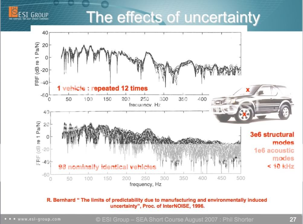
Now, what does that got to do with headphones? Well, it's a complex build up structure too so it is the subject to just the same physics... But, it's all very small scale so even 20kHz is basically "low frequency" behavior (not so many modes in the cavities, no modes in the structure, not so complicated joints between the parts...). The only exception is the diaphragm (zillions of modes...) but as mentioned by Bob earlier in the thread, pretty much only the first "pumping" mode seems to contribute efficiently to the response and it is only sensitive to the tensioning (and diaphragm thickness/properties but I assume this is well under QC). I guess, in the case of Stax, it means tensioning and diaphragm properties + ear pad shape are the main source of variability across samples. As Tyll pointed out, there are probably more repeatability issues with the measurement itself (e.g. how much clamping on the phone and actual position on the dummy).
-
Hey Tyll, not sure about your night vision skills but I have a hard time reading bright yellow over white lol
-
I am not sure about the various waterfall graphs which have been posted here either, in part since I assume they must also be based on some sort of impulse signal which would presumably be subject to the same artifact noted above. I am have having some problem following some of this discussion as to what is an actual measured response, what is derived from existing data and what is some kind of hypthetical simulation.
The Frequency response data seems interesting and uncontroversial. But I would mention some additional points of testing or discussion which it would be nice to see clarified..
First whether the measuring set-up is properly compensating for pinna and ear canal effects so as to measure "flatness." comparable to measurements of speakers. It is my understanding that the system does ini fact attempt to do this but exactly how I am not sure.
Secondly there is the issue of repeatability. To what extent you are getting positioning effects such that the measured response could change with a slight tweaking of position of the phones i.e. if the same phone is measured at different times is the response going to look the same.
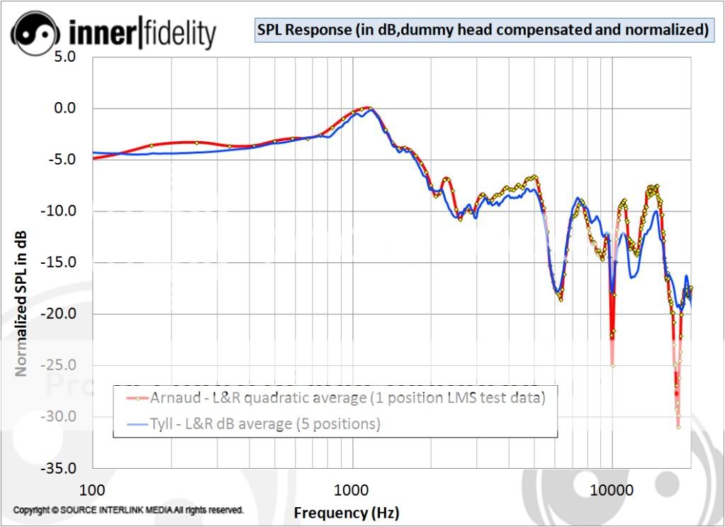
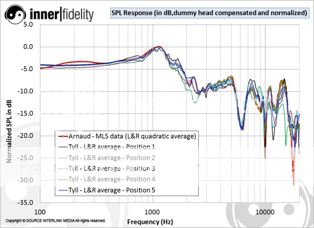
Here is a confirmation that the FFTs I am doing in Excel are correct and that impulse response data I am using is in the range of the other measurements done by Tyll to generate the "spaced averaged (5 locations) and equalized (compensated for dummy head response) magnitude response plots:
-
I am not sure about the various waterfall graphs which have been posted here either, in part since I assume they must also be based on some sort of impulse signal which would presumably be subject to the same artifact noted above. I am have having some problem following some of this discussion as to what is an actual measured response, what is derived from existing data and what is some kind of hypthetical simulation.
I have now updated the recent CSD and FRF plots by applying Tyll's equalization referred as "Independent of Direction Equilization Parameters" in his spreadsheets. It doesn't seem to be a diffuse field equalization, maybe Tyll could clarify.
SR007 vs SR009:
Comparisons with HD800, LCD2r2:
PS: the normalization is a little "rough" because the frequencies for which I have the equalization values are not exactly matching those for which the CSDs are computed...
PPS: Ed, just to clarify the method: these CSDs are all using the same test data which is an impulse response measurement for 1 headphone position. I haven't compared my FRFs (i.e. the t=0 on the CSD graph) with those of Tyll but will shortly and report...
Audeze LCD-3
in Headphones
Posted
As far as the diaphragm is concerned, it's basically clamped by the spacers but having basically not flexural stiffness (it's such a thin piece of plastic it can't even holds its own shape), you can't expect some "clamped" dynamics like a beam fastened on a vice... It's more like what is called "pinned boundary conditions" (i.e the membrane can freely rotate even on the very edge common to the spacer).
Or maybe you're asking about the stator itself? Maybe Birgir can say for this one (he's got to be tempted to crack this thing open at some point!).
Well done! You got talent to boil down what's seemingly complicated into simple understandable concepts.
Birgir, where did you get this info from? I went through the interviews and never could understand the reason for the center hole. My assumption was either to increase acoustic transparency at higher frequencies or gain some dynamic headroom (never could precisely work out actual displacements of the diaphragm but simulation suggested it would have to be no less than 0.1mm or 0.2 mm for 100dB output at the first diaphragm resonance, e.g. 60Hz or so).